Zarathustra[H]
Extremely [H]
- Joined
- Oct 29, 2000
- Messages
- 40,957
To follow up on this.
Even if the Freezemod pump only hits a max of ~480 L/h like the traditional 3.2 DDC pump does in EK's testing, that is still ~2.1 GPM. Even with some loss due to head pressure, I should wind up getting WELL above the 1GPM "rule of thumb" level considering all they will be pushing through is a single (albeit huge) radiator each (2 of them) and one CPU block (one of them).
And DDC pumps tend to have higher head pressure than D5 pumps, so while they start at a lower flow rate, they lose less of it to resistance in the loop than a D5 does.
According to some testing I've seen, a DDC pump ought to lose me less than 10% flow rate with only one block in the flow path. That's still a worst case of ~1.89 GPM for the workstation block. It's probably about the same for the huge radiators. And that is way more than sufficient.
By contrast, a typical D5 (regular variety, not D5 Strong or 24v D5) tends to be speced at 1500L/h (~6.6 GPM) but drops off way quicker due to loop resistance due to the lower head pressure. Effective flow with only one block in the loop ought to be ~3.9 GPM (depending on the block). In a more typical full loop with two blocks (CPU and GPU) and two (normal sized) radiators my experience is that they tend to drop down to between 0.85 and 1.3 GPM depending on the loop particulars and how many restrictive components are in there.
I'm still going to keep the D5's for the game system subloops. In that application, the up to 25w each they dump into the loop is probably warranted. I want to maximize the flow across those blocks to minimize the temperature delta between the core and the coolant.
In my original design I had intended to use two D5's in serial for a single loop with both blocks in it, but I am considering actually splitting it up with one D5 per block instead, as generally reducing resistance tends to have much more effect than adding pressure by adding pumps in series.
This has multiple benefits. On the one hand, my theoretical flow rate goes up (to a potential 3.9GPM per block) which ought to keep the delta between the cores and coolant as low as possible. But this is probably overkill. I plan on testing speed settings and see at what flow rate I start seeing seriously diminishing returns on delta T and cap the max PWM speed there, as this will mean less power used by the pumps, less pressure on my loop joints, and less heat (from the D5 pumps) dumped into the loop.
(I am going to try to do some similar optimization on the DDC's pushing through the radiators and the workstation block as well)
Another benefit from using one pump per block is that I don't need to use loop temperature sensors and the Aquaero as a speed control device. I can just use the motherboard fan header (based on actual core temps) to control the pump speed for the CPU block, and I can usually tap into the PWM signal originally going to the GPU's fans to control the pump for the GPU block.
(this works well in large part since I have decoupled the radiator flow and the block flow, otherwise this would be suboptimal, as at low core temps the fluid in the loop would be allowed to slowly heat up, and then if there is a sudden load, there will be a temp spike, before the fluid can be cooled down by the radiators.)
This is what I did (but for fan speed instead of pump speed) back when I used two AIO's to cool my dual 980ti's in 2015 using Corsairs HG10 N980 adapter bracket.
View attachment 707206
View attachment 707205
At least on those cards (EVGA 980ti's) I found that while they used a mini-fan header, it was still the same PWM signal as for regular PC fans, and still 4 pins, and the same pin layout as the standard PC fan header.
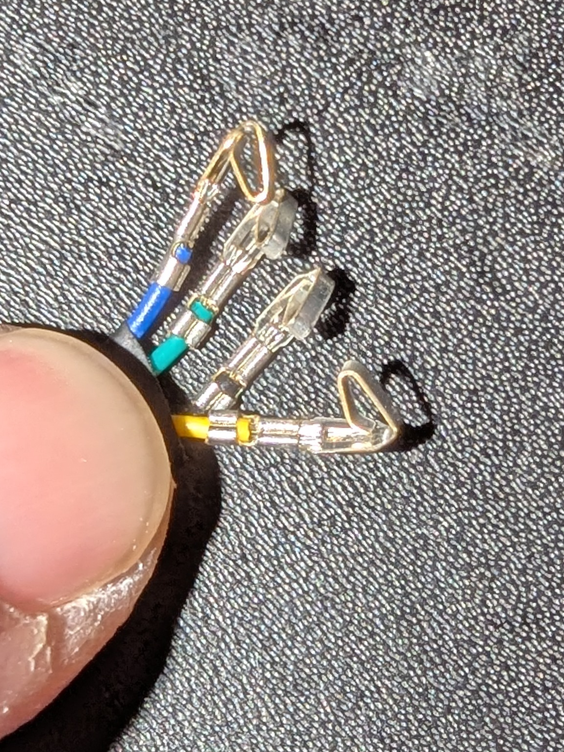
So I just made my own wiring harnesses to adapt the PWM and RPM signals to instead control the 140mm fans blowing through the Corsair H90 (though I didn't pull any power from the GPU as I didn't know how much power that header could handle)
This resulted in the fan speed being fully controllable by the GPU's firmware, or even GPU tools like MSI Afterburner.
Hopefully this is still the case.
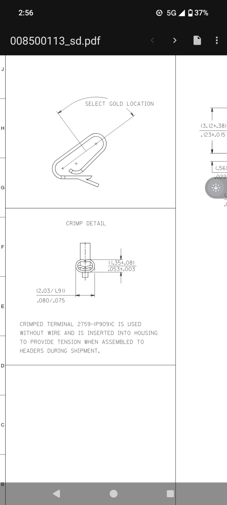
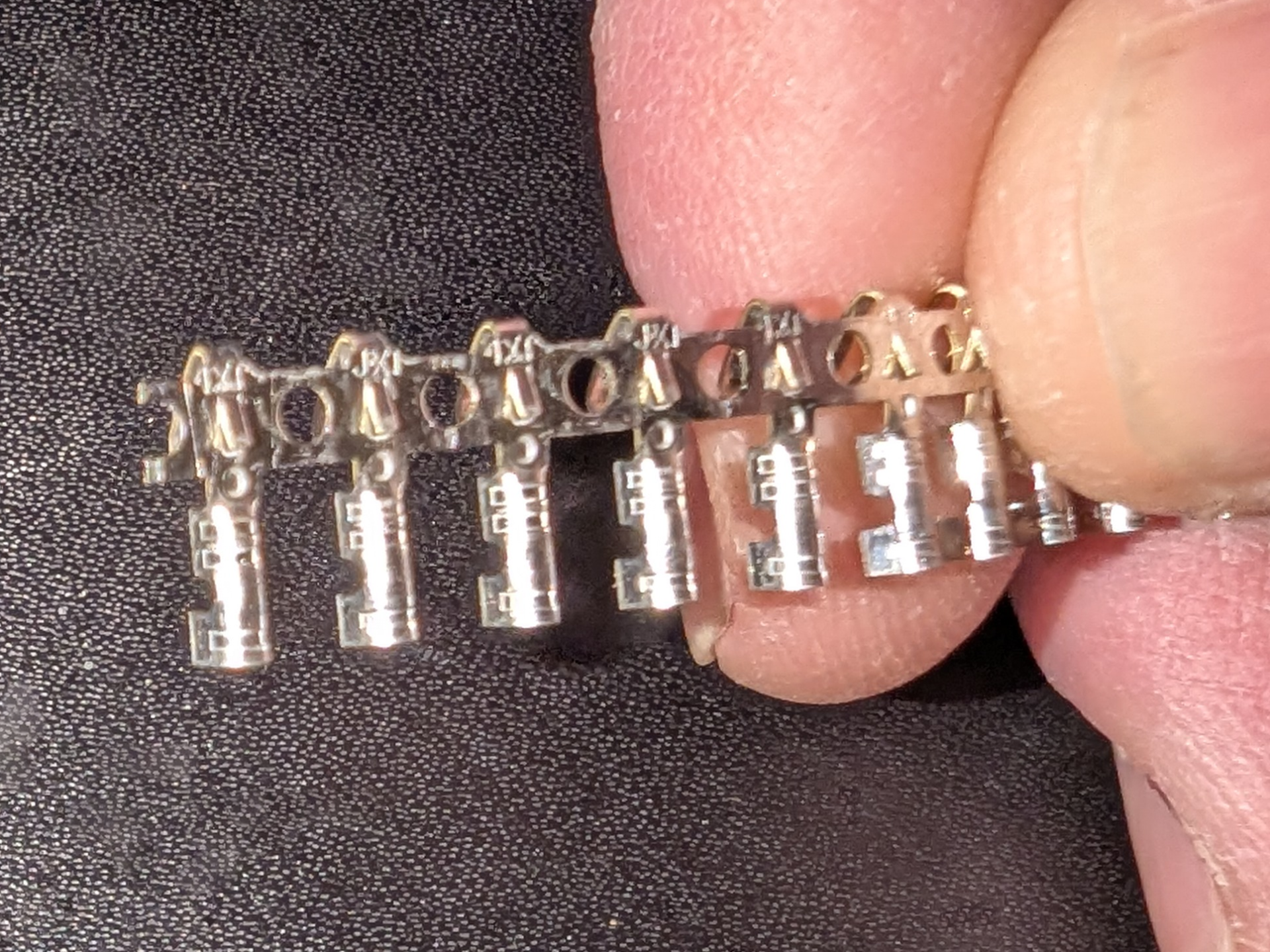
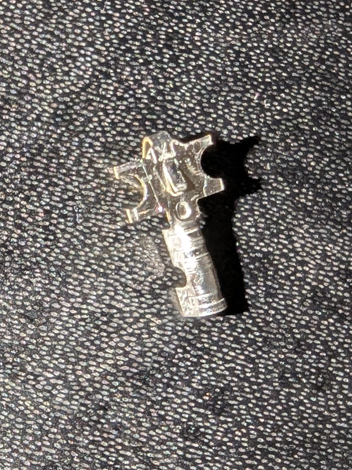
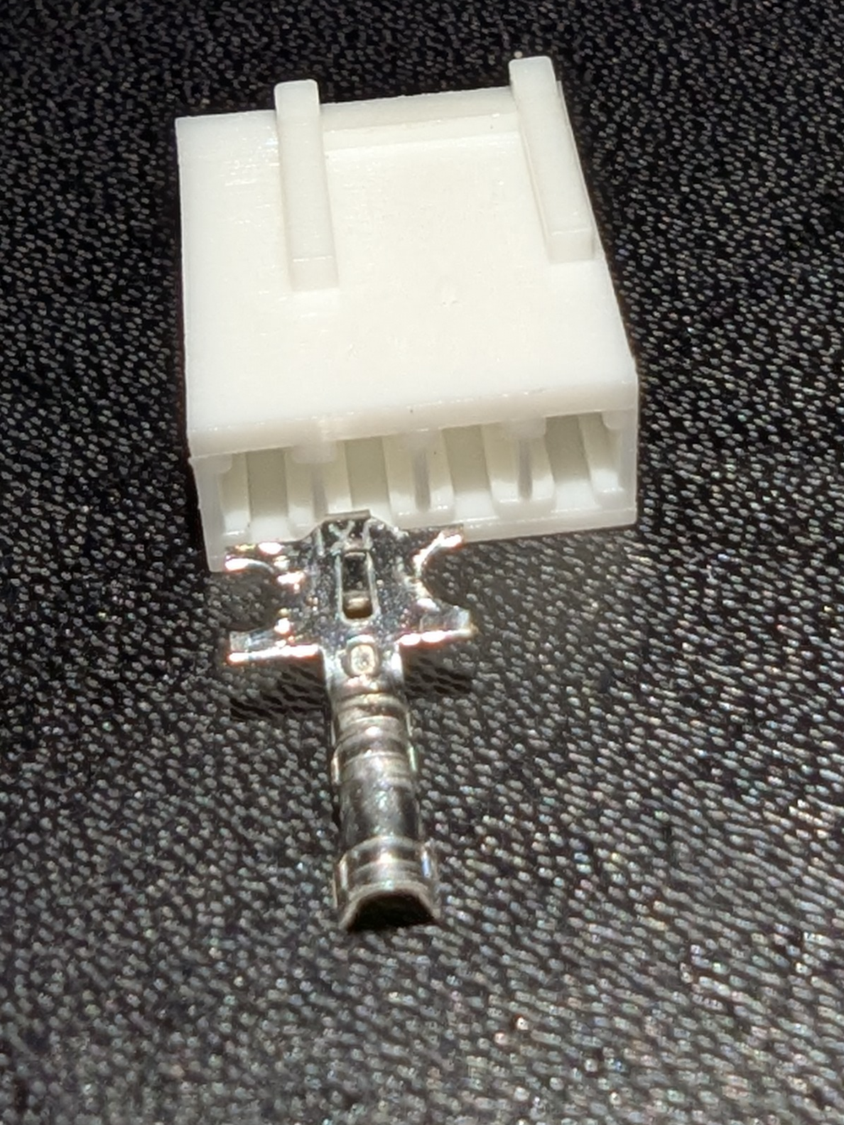
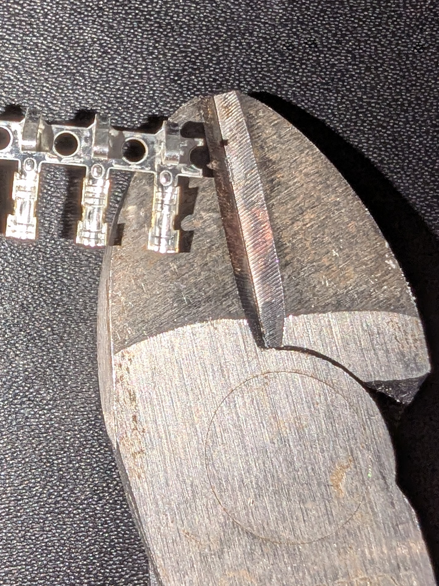
My recollection from that project (though it has been a hot minute) is that the hardest part was actually finding a mating connector that would plug into the mini-fan header on the GPU. (I didn't want to destroy the stock coolers by cutting off and using their plugs). If I recall I did some exhaustive searching and eventually only found them as part of some completely unrelated wire harness, and bought two of those and lopped off the connectors.
For what it is worth, I just reviewed the pictures I took back when I put the water block on my 4090.
It appears as if at least MSI still used the same mini-fan headers, at least as of the 40-series.
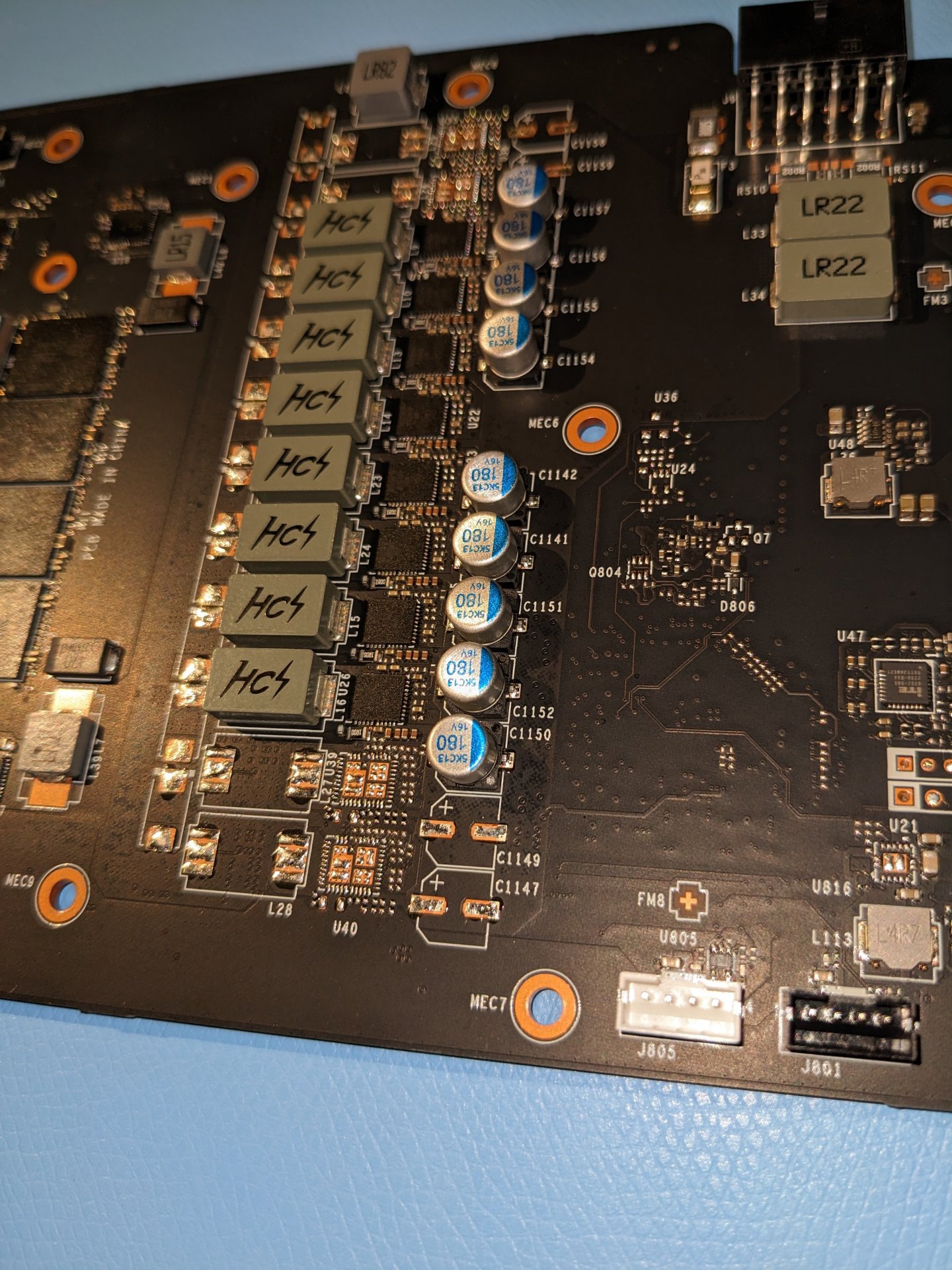
With any luck, the AIB 5090's will do the same.
Even if I see a connector like this - however - I'm going to have to measure carefully, as this is not a standard, and there is no guarantee they use them the same way.
As an example, the MSI 4090 had two of them, a white one and a black one. If memory serves (though I'd have to go dig out the cooler to confirm) the black one was for the RBG LED's.
![[H]ard|Forum](/styles/hardforum/xenforo/logo_dark.png)
