• Some users have recently had their accounts hijacked. It seems that the now defunct EVGA forums might have compromised your password there and seems many are using the same PW here. We would suggest you UPDATE YOUR PASSWORD and TURN ON 2FA for your account here to further secure it. None of the compromised accounts had 2FA turned on.
    Once you have enabled 2FA, your account will be updated soon to show a badge, letting other members know that you use 2FA to protect your account. This should be beneficial for everyone that uses FSFT.

The Z Build(s) 3.0 - Go Big and/or Go Home

To follow up on this.

Even if the Freezemod pump only hits a max of ~480 L/h like the traditional 3.2 DDC pump does in EK's testing, that is still ~2.1 GPM. Even with some loss due to head pressure, I should wind up getting WELL above the 1GPM "rule of thumb" level considering all they will be pushing through is a single (albeit huge) radiator each (2 of them) and one CPU block (one of them).

And DDC pumps tend to have higher head pressure than D5 pumps, so while they start at a lower flow rate, they lose less of it to resistance in the loop than a D5 does.

According to some testing I've seen, a DDC pump ought to lose me less than 10% flow rate with only one block in the flow path. That's still a worst case of ~1.89 GPM for the workstation block. It's probably about the same for the huge radiators. And that is way more than sufficient.

By contrast, a typical D5 (regular variety, not D5 Strong or 24v D5) tends to be speced at 1500L/h (~6.6 GPM) but drops off way quicker due to loop resistance due to the lower head pressure. Effective flow with only one block in the loop ought to be ~3.9 GPM (depending on the block). In a more typical full loop with two blocks (CPU and GPU) and two (normal sized) radiators my experience is that they tend to drop down to between 0.85 and 1.3 GPM depending on the loop particulars and how many restrictive components are in there.

I'm still going to keep the D5's for the game system subloops. In that application, the up to 25w each they dump into the loop is probably warranted. I want to maximize the flow across those blocks to minimize the temperature delta between the core and the coolant.

In my original design I had intended to use two D5's in serial for a single loop with both blocks in it, but I am considering actually splitting it up with one D5 per block instead, as generally reducing resistance tends to have much more effect than adding pressure by adding pumps in series.

This has multiple benefits. On the one hand, my theoretical flow rate goes up (to a potential 3.9GPM per block) which ought to keep the delta between the cores and coolant as low as possible. But this is probably overkill. I plan on testing speed settings and see at what flow rate I start seeing seriously diminishing returns on delta T and cap the max PWM speed there, as this will mean less power used by the pumps, less pressure on my loop joints, and less heat (from the D5 pumps) dumped into the loop.

(I am going to try to do some similar optimization on the DDC's pushing through the radiators and the workstation block as well)

Another benefit from using one pump per block is that I don't need to use loop temperature sensors and the Aquaero as a speed control device. I can just use the motherboard fan header (based on actual core temps) to control the pump speed for the CPU block, and I can usually tap into the PWM signal originally going to the GPU's fans to control the pump for the GPU block.

(this works well in large part since I have decoupled the radiator flow and the block flow, otherwise this would be suboptimal, as at low core temps the fluid in the loop would be allowed to slowly heat up, and then if there is a sudden load, there will be a temp spike, before the fluid can be cooled down by the radiators.)

This is what I did (but for fan speed instead of pump speed) back when I used two AIO's to cool my dual 980ti's in 2015 using Corsairs HG10 N980 adapter bracket.

View attachment 707206

View attachment 707205

At least on those cards (EVGA 980ti's) I found that while they used a mini-fan header, it was still the same PWM signal as for regular PC fans, and still 4 pins, and the same pin layout as the standard PC fan header.

So I just made my own wiring harnesses to adapt the PWM and RPM signals to instead control the 140mm fans blowing through the Corsair H90 (though I didn't pull any power from the GPU as I didn't know how much power that header could handle)

This resulted in the fan speed being fully controllable by the GPU's firmware, or even GPU tools like MSI Afterburner.

Hopefully this is still the case.

My recollection from that project (though it has been a hot minute) is that the hardest part was actually finding a mating connector that would plug into the mini-fan header on the GPU. (I didn't want to destroy the stock coolers by cutting off and using their plugs). If I recall I did some exhaustive searching and eventually only found them as part of some completely unrelated wire harness, and bought two of those and lopped off the connectors.

For what it is worth, I just reviewed the pictures I took back when I put the water block on my 4090.

It appears as if at least MSI still used the same mini-fan headers, at least as of the 40-series.
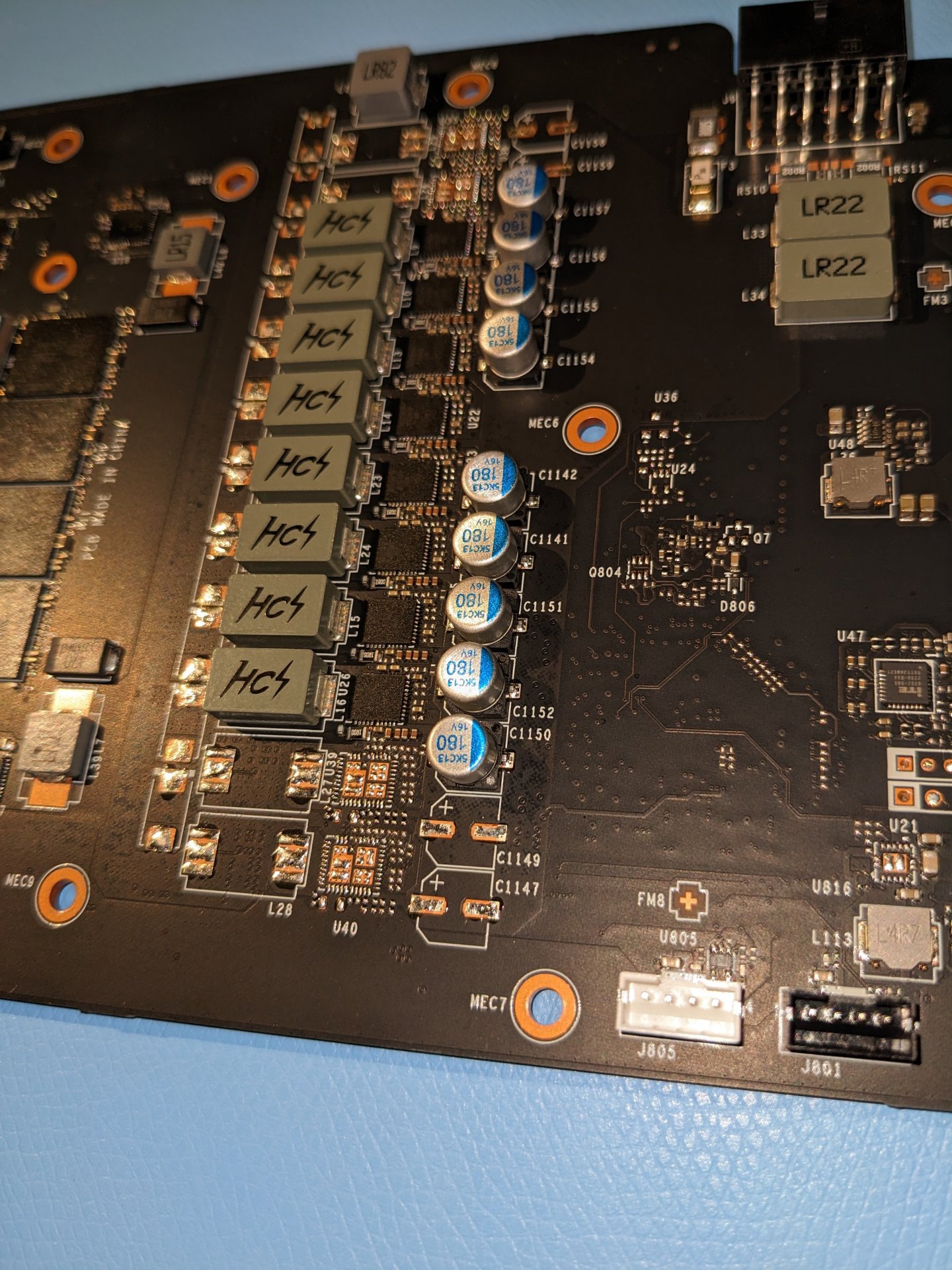
1738191347132.jpeg


With any luck, the AIB 5090's will do the same.

Even if I see a connector like this - however - I'm going to have to measure carefully, as this is not a standard, and there is no guarantee they use them the same way.

As an example, the MSI 4090 had two of them, a white one and a black one. If memory serves (though I'd have to go dig out the cooler to confirm) the black one was for the RBG LED's.
 
for what its worth, my 6700's mini connector is pwm, im using an adapter to run an 80mm off it.

Do you happen to have a link (or any identifying name or part number) for that adapter? I remember having a real hard time finding that connector a decade ago, and apparently I never mentioned any of the identifying information in any of my posts on the subject, and I can't find it in my order history.

I thought I had saved my custom harnesses, but guess what, I can't find those either. Maybe I threw them out at some point.
 
As an Amazon Associate, HardForum may earn from qualifying purchases.
Just make sure the pins go to the right wires on the fan -- don't want to let out the magic smoke!
 
Just make sure the pins go to the right wires on the fan -- don't want to let out the magic smoke!

Absolutely. Not my first rodeo. I'd be testing, double testing and triple testing that with my multimeter before powering it up the first time :p

I kind of wish I had an oscilloscope so I could measure PWM signals. Maybe some day. It's not in scope for this project. This is getting expensive enough as it is :p

Should be fairly simple though. PWM and RPM signal go to pump. Separately, +12v and ground go to pump.

I'm guessing the pinout is probably going to be the standard pinout, same as fan standard sized fan headers:

Pin1: GND
Pin2: +12V
Pin3: RPM
Pin4: PWM

But I will thoroughly test that before hooking anything up.

Between the adapter linked above, and the fact that most pumps have separate power and RPM/PWM connectors (due to their high current draw) the chances of frying anyhting seem pretty low.

My plan is to do some experimentation on the GPU cooler first, to see if the fans respond as expected to ground and voltage on Pin1 and Pin2, and if I can manipulate fan speed as expected on pin 4 (ground, 0% duty cycle, not connected 100% duty cycle).

This is about the best I can do without an oscillator or oscilloscope. (though I hear some multimeters these days allow for some basic frequency mesurement.)
 
Last edited:
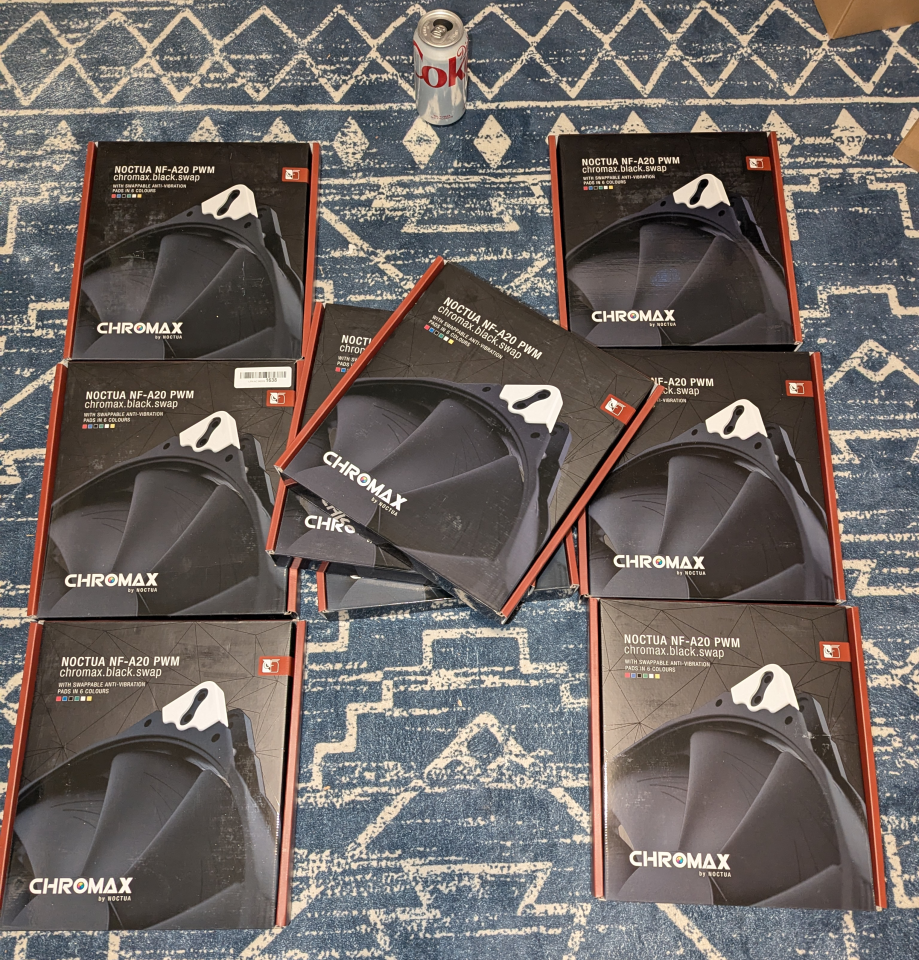
The first 9 200mm fans came in. I was going to order them all at once, but the seller with the best price only had exactly 9 left in stock, so I figured that would do for now.

I keep forgetting how massive these things car.

Die Coke (sorry, once again no banana) for scale.

1738357952023.png


I'm undecided what color to use for the corners. I mean, I really don't care that much. I'll probably just go with black, but white might add a nice little accent for contrast.
 
This is actually way nicer than I expected.

I have one of these Noctua 200mm fans in my testbench build already (in the front of a Phanteks Enthoo Pro case (I had to Dremel it down a bit to make it fit) but I had forgotten that they come with a detachable cable.

PXL_20250131_230906211.PORTRAIT.ORIGINAL.jpg


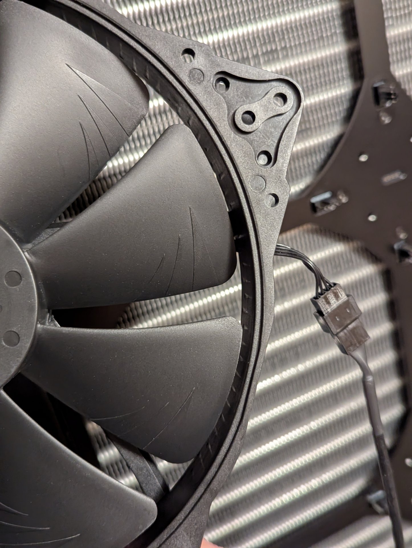
Once you pull the long cable off, you are left with a short little pigtail, that is just long enough to properly mate with the fan header on the fan bracket.

PXL_20250131_231008907.jpg


Just holding the fan in place to illustrate this, it winds up being next level when it comes to cable management. This is huge and is going to save me a lot of headaches.

Only downside is I wish the Noctua 200mm fans moved more air.
 
Spent some time opening Noctua fan boxes, installing black vibration pads, and installing them on the first radiator bracket last night.

Unlike most radiator screws, Watercool has gone with a short screw that only goes through the side of the fan that is closest to the radiator, unlike the long ones that go through both sides.

...and they use a 2.5mm allen key, which I am lucky I was able to find. I have hex pattern bits for my screwdrivers, but none of them were slim enough to go through the top fan hole to reach the screw behind them.

This is not difficult stuff, but it is a lot more time consuming than I gave it credit for before starting.

And then - of course - when I got to the last box, it looks to have been tampered with. Missing the fan cable, and the box with all the silicon vibration dampeners, so it will have to go back, and I only have 8 fans until the next arrives...

PXL_20250202_030139454.PORTRAIT.jpg


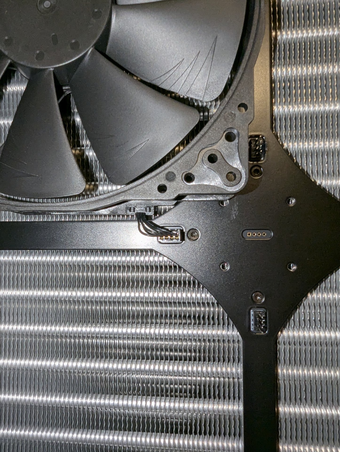
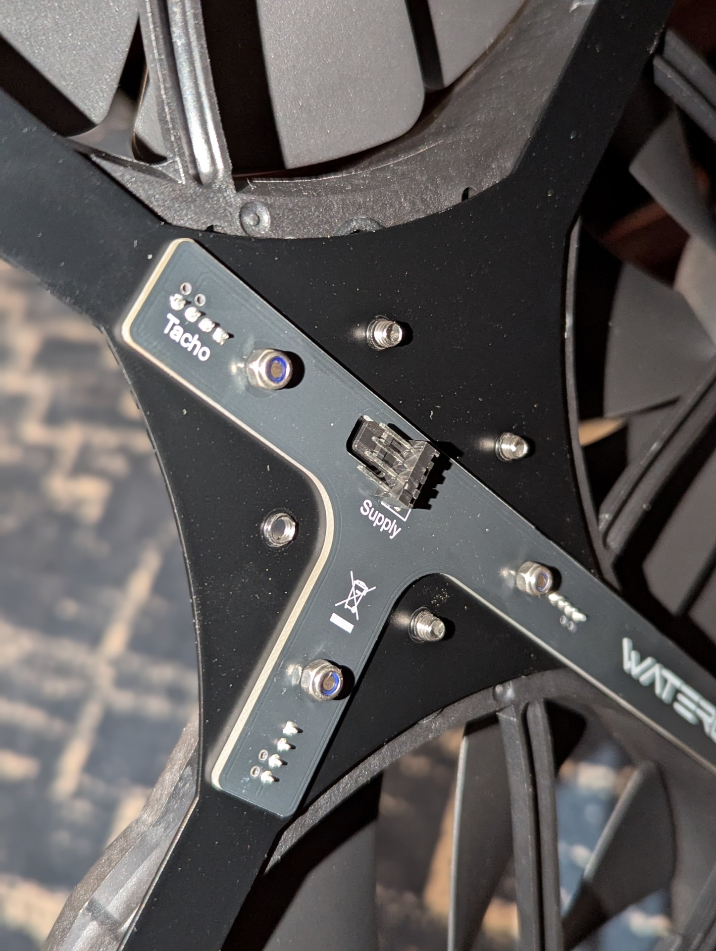
I also discovered that while the brackets with the integral fan splitters are really cool, there is one annoying thing about them:

PXL_20250202_030205725.PORTRAIT.jpg


They are supplied on the back by a male fan header.


Apparently if you buy one of Watercools two controllers that assemble into the radiator on the side on the bottom (standalone auto one, or one that feeds off of a fan header in the PC) you get the male to male fan cable in the package. Since I have like three Aquaero 6 devices already though, I wasn't planning on doing that. I really like my Aquaero's, and more importantly, they are already paid for.

I poked around a bit, and was unable to find any male to male fan cables to buy, so I will have to make my own fan cables.

This is probably for the best anyway, as they are going to need to be quite long in my application. This will force my hand to actually spend the time to make my own cables. Otherwise I would probably just have strung together a series of fan extension cables, which would not have been very reliable.

Just to make sure there wasn't anything funky going on, I grabbed my multi-meter and did some brief continuity testing. On the fan header I randomly selected on the front - as expected - all pins showed continuity in the same order on both sides, except the RPM pin which was not connected. (it is probably connected to one of the fan headers on the front, but I am not sure which one. (probably the one that says "tacho" on the back) The reason for this is that RPM signals work by pulses. If you have two fans sending back pulse data on the same conductor, it will be read as twice the RPM. Tie 9 together - and if there is enough separation in the signal, it will be read as 9x the rpm)
 
I had originally planned on making my own brackets from ABS for the reservoir mounting, but in a moment of weakness I thought "why reinvent the wheel" and ordered those too.

They arrived last week, and I installed them yesterday.

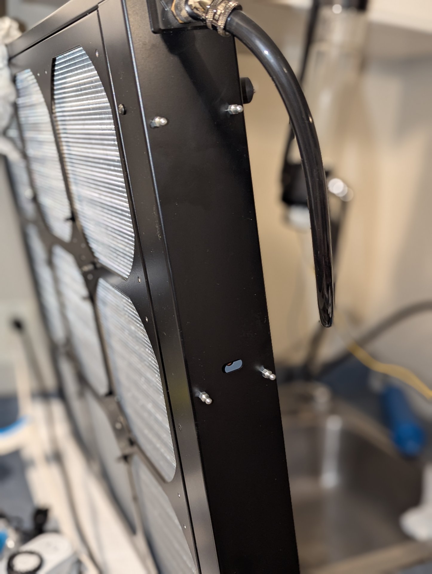
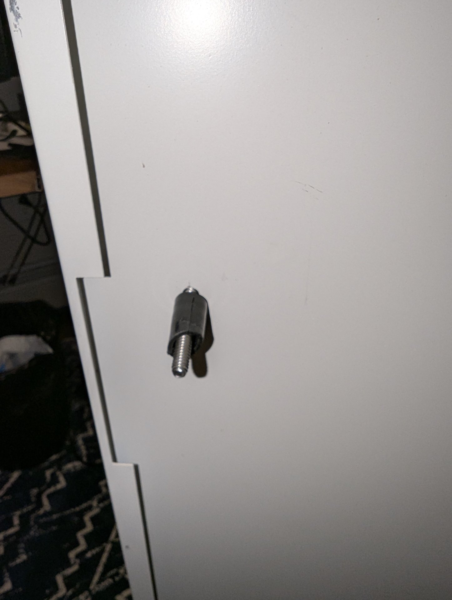
The bracket comes with these screw in pins:

1738466890649.jpeg


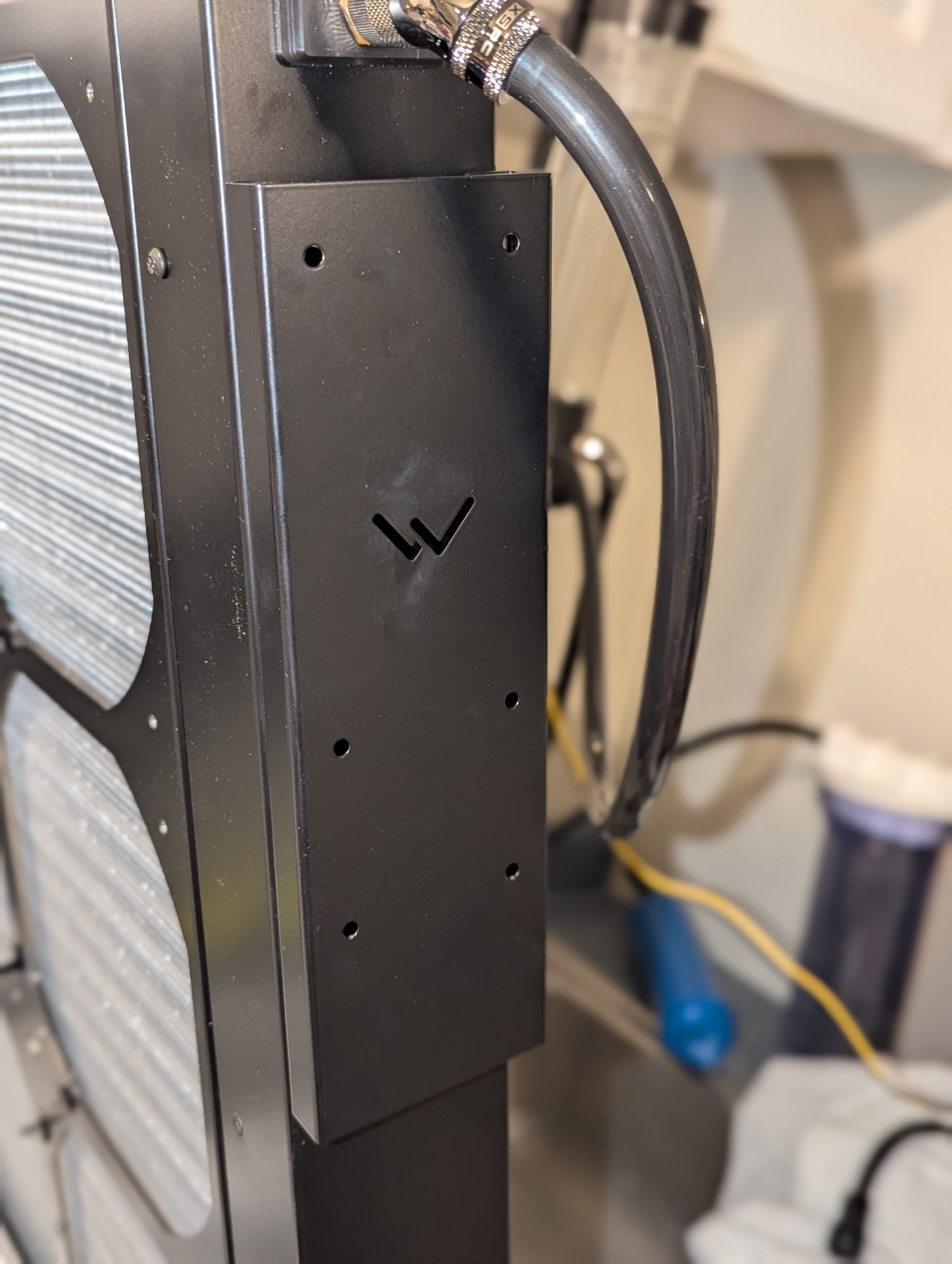
The pins then press into matching slots on the back of the brackets:


PXL_20250201_025846187.PORTRAIT.jpg


In my original plans (that only existed somewhere in my head) I was going to mount the reservoir much further down, such that a pump hanging off of the bottom of the reservoir can push coolant straight into the bottom port of the radiator as an inlet.

The top radiator port was going to be the return and enter back into the reservoir (at first) and when I got the second one set up, I was going to run it into the second reservoir below. This was going to be made easier and more flexible by using some Koolance QDC's on the line exiting the radiator. With the brackets as high as they are, even if I mount my reservoirs at the very bottom of them, I unfortunately think there just isn't enough space there to include the QDC's now, which is a shame, and means I am going to have to get more creative when I attach the second radiator to the loop.

...or maybe I'll just do them at the same time to save some effort.

I still very much plan to have QDC's on the lines going to the computers though, as this will facilitate easy future upgrades.
 

I guess that consideres what you consider male and what you consider female. I've always viewed these from a connector perspective, in which case the standard connector on a fan sticks inot the header on a motherboard making it male, and the motherboard header female...

That said if you look at it from the pin perspective, then the typical motherboard header is male, and the typical fan connector is female.

(whoa @ gender fluidity 😂 )

It sounds like you have interpreted it the way the industry does, and I was wrong, which is why my searches were unsuccessful and you have found something.

The one you have found is intriguing, as it is 24" long. That might just be long enough. I am going to ahve to do some measurements when I get things in place.

I am still totally thinking of making my own through.
 
Today I went back to the drawing board (if only a tiny bit)

Some Prepwork

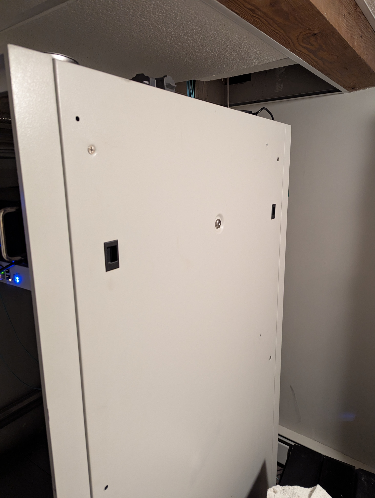
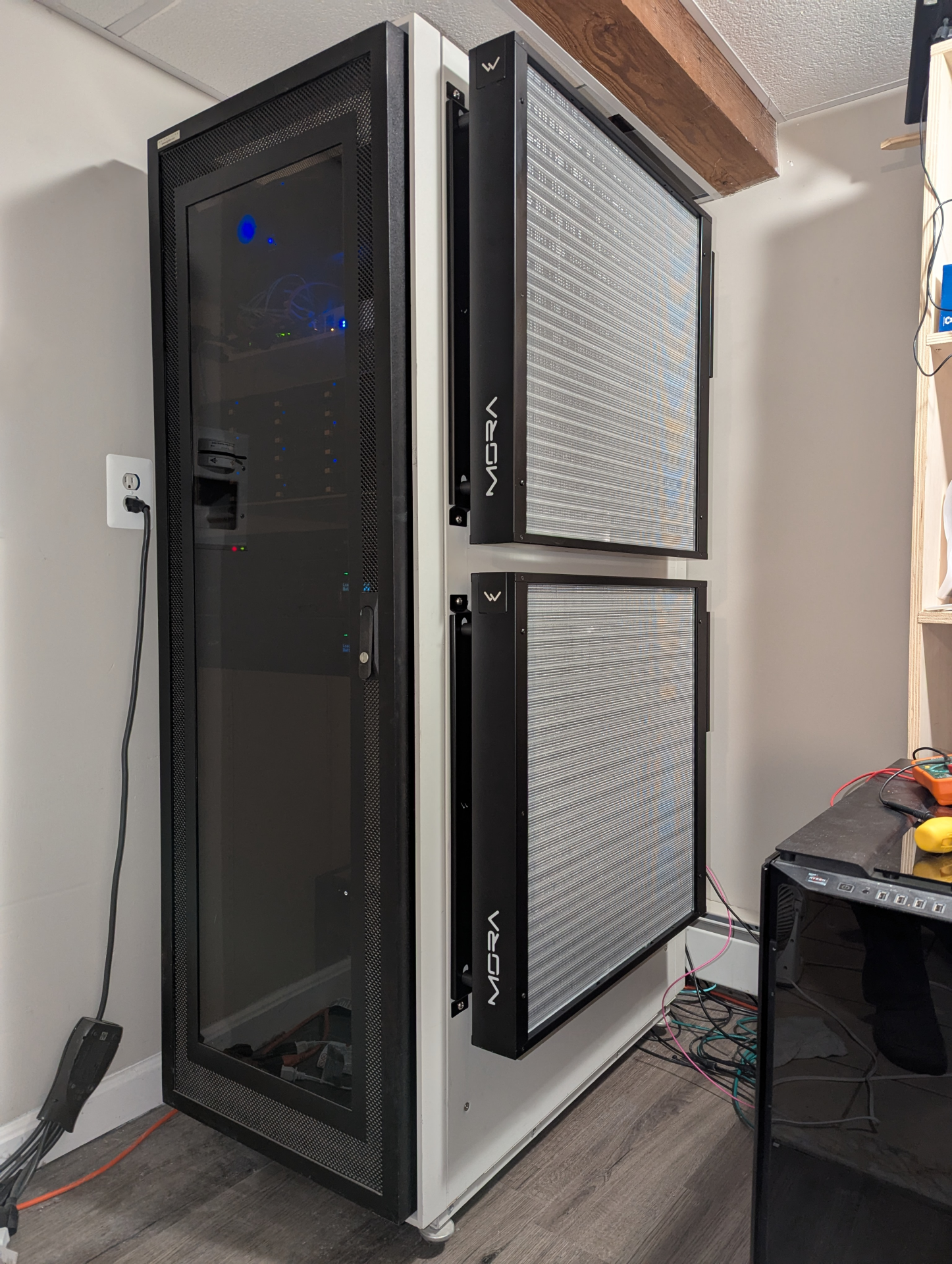
I spent some time looking at the rack a few days ago, and noticed that the side panel I was planning on hanging everything from is really only held on by some plastic latch handles:


View attachment 701951

Those two little black handles, and a wimpy lock (for which I do not have the key) are what secure the whole thing in place.

I put some test weight on it (me, hanging from the side of the thing), and damn, the panel started to pull away from the rest of the rack. So I needed to reinforce that puppy before I start hanging heavy water filled radiators and reservoirs from it.

Looking at the rack from the inside I noticed that the back of the main rails (where you screw in the sliding rackount kits) has 1/4" screw holes about every half inch running top to bottom on both the front and rear of the unit.

I decided to drill matching holes on the panel itself, and install some machine screws through the holes with bolts on the back. I figured that should secure it up nicely.

I figured I'd pout one hole front and back up top, in the middle and down at the bottom, 6 bolts in total. That ought to do it.

I noticed the rack shelves were in the way up top and on the bottom, so they would need to come out for me to gain access.

These things are heavier than they look:

View attachment 701952

They are made of 1/8" thick sheet metal, with reinforcement in many places. Real heavy.


They came in the rack, and probably date back to the 90's. I haven't seen modern rack shelves (this is the one and only rack I've had the pleasure of working with) but I am going to go out on a limb and suggest "they probably don't make them like this anymore".

After a quick trip to home depot to buy the fasteners, bolts (and some lock washers for good measure) I started the drilling. I bought a new kit of drill bits when I was there as I did a massive home improvement project this summer, and have either lost or burnt out most of my previous drill bits.

I wound up with some Milwaukee "Shockwave Titanium" bits, because they were on sale. (I have no tool brand loyalties). They claim they stay sharper longer, and I was actually pretty impressed with the first hole. I applied a little cutting lubricant to the bit and started drilling, and it went through the sheet metal like butter.

I'm not sure about the "stays sharper longer" claim though, as already by the second hole it took some more force. By the last, I had to put some muscle into it.

But all the holes are drilled, and bolts installed, and the panel is now very secure.

View attachment 701953


Because I was worried about the bolts interfering with the shelves (or other things) when I put them back in, I flush cut the back of the screws with the tightened down nut using my oscillating tool and an "extreme titanium metal/whatever" blade.

View attachment 701954

In this process I learned that oscillating tools can loosen tightened bolts (even with a lock-washer in place) so once done, I re-tightened them all.


Here are the top four screws in place. (the bottom two are hiding behind the Corsair 1000D)


View attachment 701957

That's all I got to today.

I am going to leave the shelves out for now, as if I put them back in, they are probably going to get in the way, when I go to mount the radiator wall mount brackets.

Unfortunately, in one of my many trips behind the rack, I must have tripped over and broken one of my 65ft display port cables connected to the back of the Corsair 1000D :/

View attachment 701958

Now I am going to be without one of my side screens until I can get and route a replacement.

That's a bummer, especially since they are like $90 each, and a pain in the ass to route across the house to my office... Oh well. Shit happens. I'm sure this won't be the last mishap before this project is done, and if it is the worst, then I will have been pretty damn lucky!


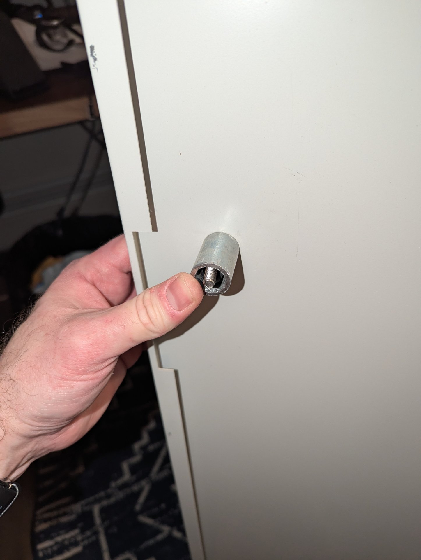
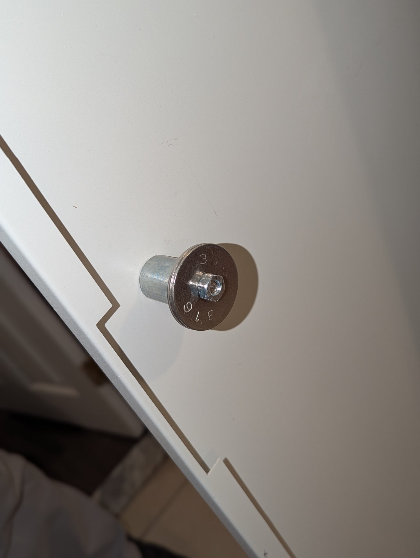
For several days now I have been thinking that I really liked my pipe-based metal spacers and how they worked to provide backing and let me tighten my screws as much as I deem necessary, and I was disappointed I hadn't thought of that sooner and done it when originally anchoring the side panel, as I definitely noticed it deflecting a little when I tightened it down.

I had mostly resigned myself to just let it be, but then when I attached the brackets to the panel last week I noticed the brackets overlapped one of the panel anchoring screws, pressing it slightly askew. (sorry I never took a pic of this apparently, thought I had)

I thought to myself, I really ought to have countersunk those screw holes....

Now I had two reasons to go back, take the brackets off the thing, and re-do my earlier work. So I did.

It was then I realized that since I haven't done a lot of work with sheet metal in my life, I'm not really sure how to counter-sink screws in sheet metal.

So I invented a way. I'm not saying I'm the first in humanity to do this (in fact, I almost guarantee I am not) but I did come up with the method myself.

After getting the panel off the side of the rack (which was a minor production, as it is locked with a key, and I never got that key when I bought it used on Craigslist years ago, but I have power tools. Nothing is impossible when you have power tools) I stuck one of the screws I wanted to counter-sink through the hole.

On the other side, I first put an old piece of primochill tubing over the screw for centering purposes, and then placed one of my pipe-based spacers over it, and then added some beefy stainless washers and a nut, and tightened it down.

PXL_20250201_020702749.jpg
PXL_20250201_020843404.jpg
PXL_20250201_021400060.PORTRAIT.jpg


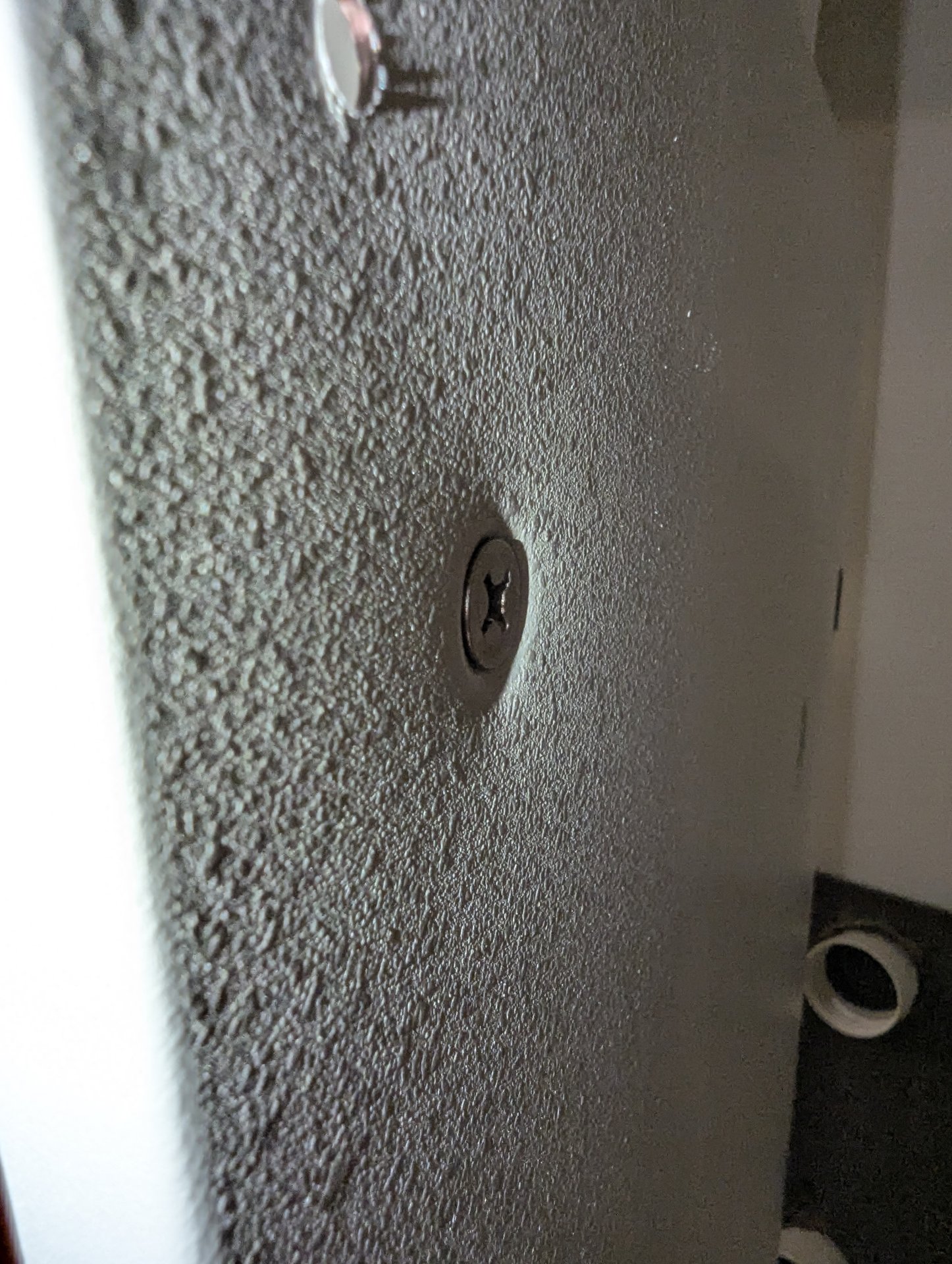
...and then I just continued tightening it (carefully) until the metal deformed and the screw was flush with the front:

1738468393656.jpeg


...and it seems to have worked!

I don't know if I have work hardened the steel or anything stupid like that in the process, but it really did the job, looks nice, and still seems strong.

I only really needed one of those screw holes counter-sunk for fit reasons, but just because I hate asymmetry and inconsistency I did it to all of them.

Now the panel is reinstalled on the rack, with it's nice counter-sunk screw holes and the spacers behind it.

1738468889616.png


Only problem now is, I no longer have enough spacers for the Watercool brackets. I am going to have to grab my cut-off saw and make some more.

Except today was snowing, nasty, wet and cold.

I'll work in the cold, but I'm not going to do this while wet, so it will have to wait.
 
Last edited:
So during the week, I cut my final spacers (as mentioned in the previous post) and installed them, so we are back where we were before last Saturday (but a bit sturdier, straighter and less flexy.)

1738979420958.jpeg


So, I started measuring for the holes to mount radiator #2, and I realized, the bottom holes are going to be right next to where the UPS:es are currently mounted.

So, I guess I am going to have to move the dreaded task of moving heavy things around inside the rack forward in the plan. And since I only want to do that once, I guess now is when I am going to have to figure out my planned rack layout. And its not as easy as it feels like it should be...

For whatever reason, the square holes for the cage nuts are not evenly spaced, and I haven't quite figured out the measurement pattern yet, making it a little confusing to figure out how individual pieces of equipment and their mounting holes are going to line up, making measurements difficult...

If there are any tricks to this from those of you who have actually worked enterprise IT and are old hand at this stuff, I'd appreciate anything you can share.

When I installed the current equipment in there I had plenty of extra space and didn't have to worry about it, but now, it is about to get a whole lot more crowded.

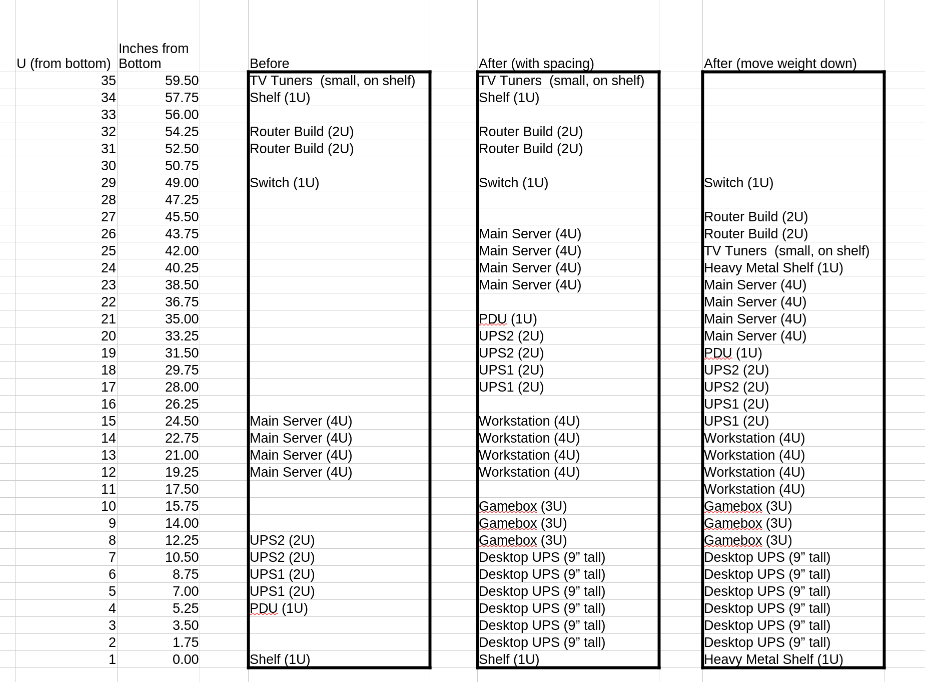
A single U is reportedly 1.75" thick, but my measurements between pieces of equipment are not lining up to be multiples of 1.75", indicating that I must have mounted some things in between "U" dividers.

Never the less, I tried to measure everything to come up with my approximate current locations for everything, and approximate future plans.

1738979300023.png


So, from the project description I ideally want things that are going to get water as far down as possible, so that critical stuff I don't want to get wet is upstream. (The NAS getting doused would be a bad day)

Unfortunately this is also in conflict with the desire to keep heavy stuff near the bottom, so that the rack is as stable as possible. I don't want some top heavy tippy thing when I am all done.


Before:
The leftmost box in the spreadsheet above represents my "before" layout, as best as I could round it off to whole rack units. (the top shelf was temporarily removed in step 1 to allow access to install the top radiator, and the TV tuners were casually placed on the thick mesh roof of the rack. The shelves are very heavy, as are the UPS:es (due to all of those lead acid batteries) so with all of those pretty far down, the rack has been pretty stable.


After (with spacing for convenience):
The middle box represents my first pass at the "After" layout, ignoring weight and stability. There are some gaps between equipment to allow for easier access when working on things.

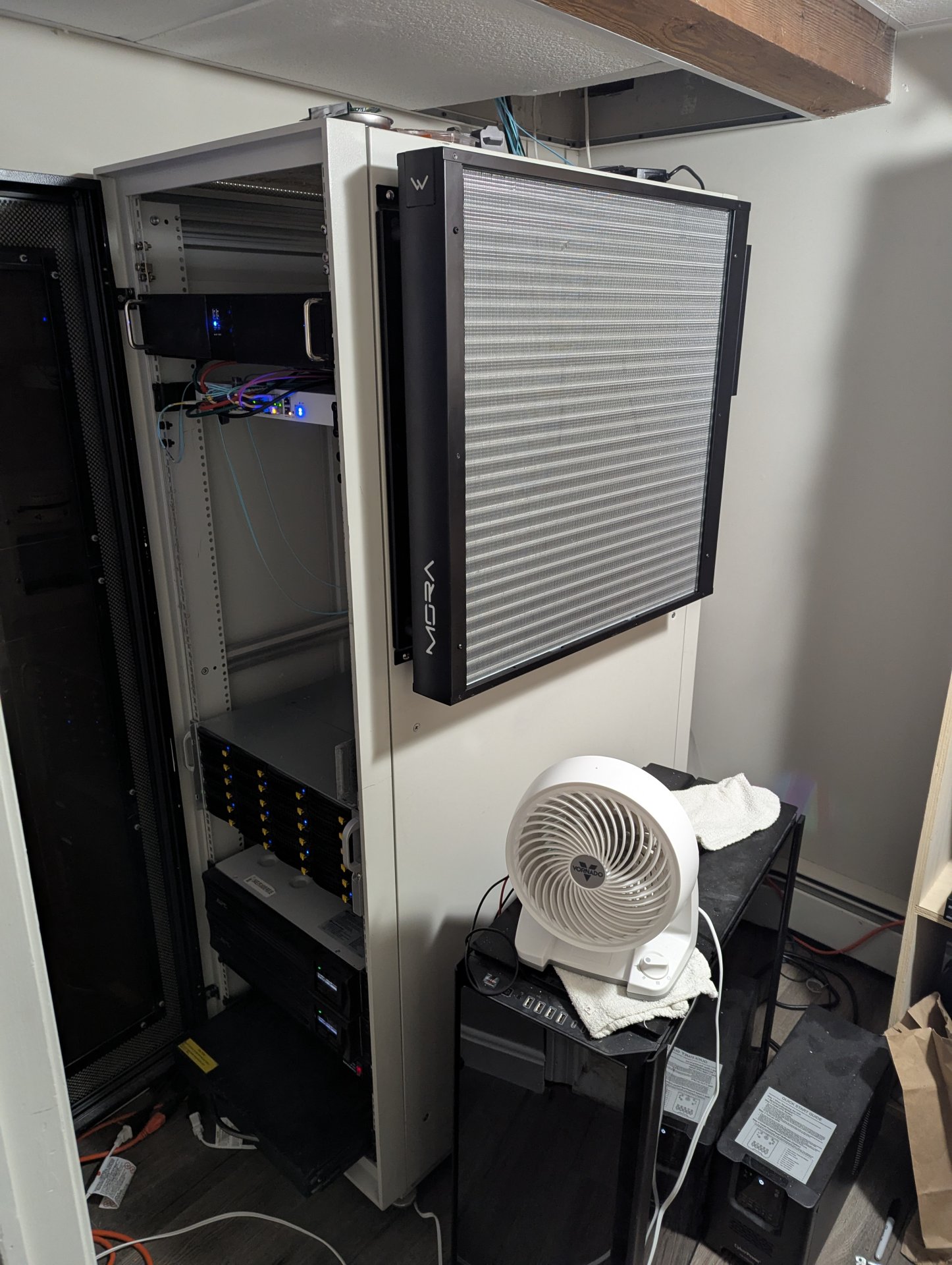
The Desktop UPS (seen in picture on floor) would move into the rack and stand on the shelf. I placed it on the bottom on the bottom as it will only be supporting the workstation and game box, so if they leak, they are going to be out of commission anyway, so I don't mind if it is under them. It is a terrible form factor for rack use, but I'd rather have it in there than on the floor. It is 9" tall, so I figure that means I need to budget the bottom 11U for it. (1U for shelf, + height of UPS rounded up to 10U)

Above that is a small (sub U) gap from rounding to closest U, and then the Gamebox, which will both be the least critical (it's just games, right?) and will have more water blocks than the workstation. so it is the highest risk. Then another little convenience gap and the Workstation above it. One water block and more critical than the game box, so it goes higher.

After that, another convenience gap and the two rackmountable UPS:es above that. These are very heavy, and I have to admit it makes me a little bit nervous that they wind up mid-rack in height. The PDU is next. While it is very light, I'd like it to be near the UPS:es for ease of cabling. Then another gap and the 4U server. This thing is also heavy due in no small part to the 12x hard drives inside it. Everything above that remains the same as in the before.


After (moving weight down as much as possible):

This is essentially the same as above, but pancaking everything down as much as possible with minor rearrangements for weight optimization.

The switch weighs almost nothing. Same with the router build and Tuners, but the heavy shelf is - well - heavy, so I brought that down to just above the file server.

I do not like this layout as much, but on the plus side, it gives a small chunk of contiguous rack units if I need to add other things in the future.


As for which layout to choose, I'm not sure. It makes me a little nervous having so much weight up high in the rack, but maybe this isn't an issue? I've never done it before. That said, I feel like while the last option may be a little better from a weight distribution perspective, but probably not significantly so.

If anyone has some experience here, I'd appreciate it. Do these types of racks on casters typically get tippy if you put to much weight up high?

I'm tempted to just go for the option with spacing. Worse comes to worse I could just anchor it into a stud in the wall if it feels tippy...
 
Oh, and in other updates.

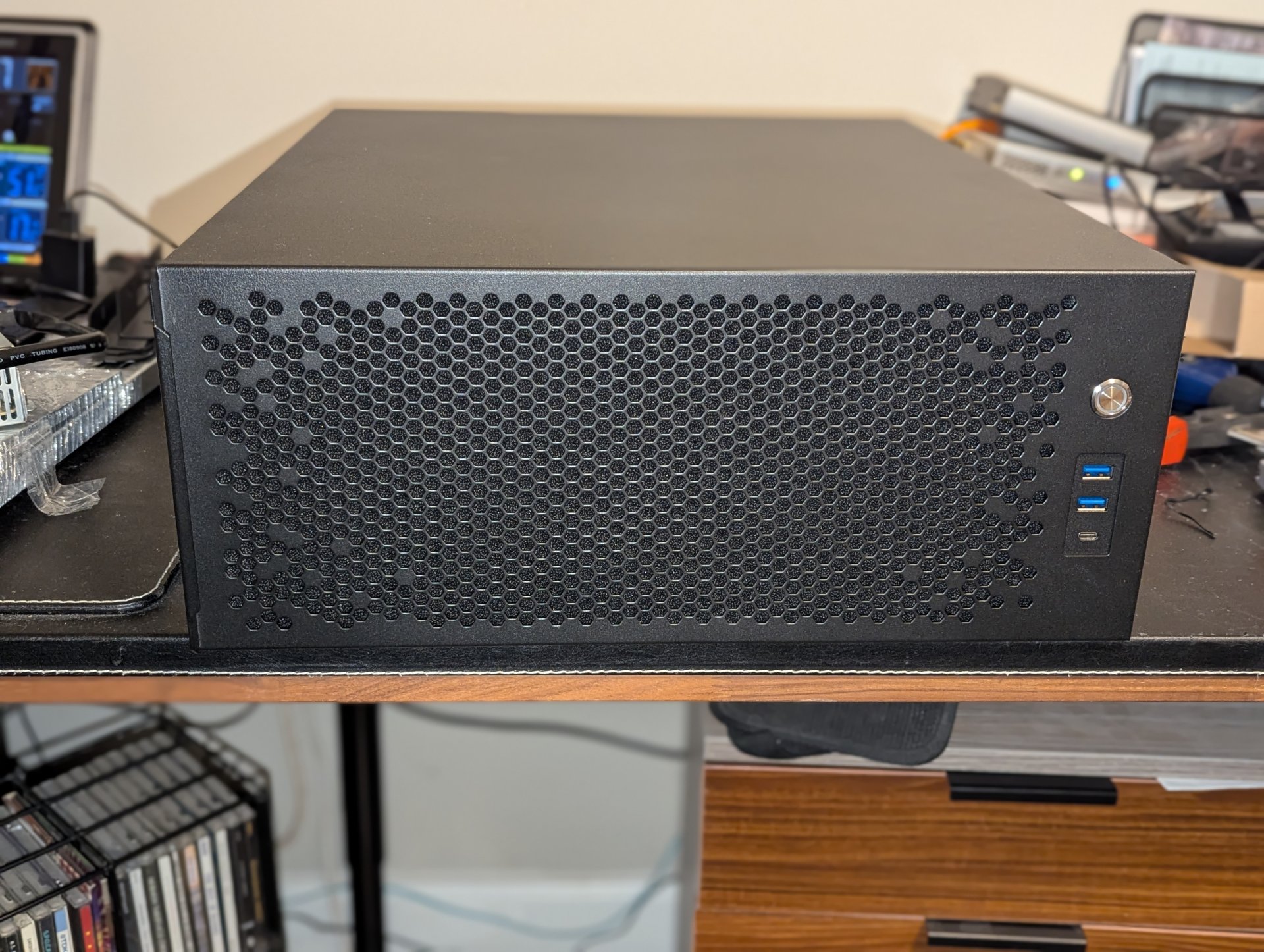
The first of the Sliger rackmountable cases arrived this week. The 4U one for the workstation.

It looks like a pretty neat case. Feels pretty sturdy. I mounted the three Silverstone fans in it, and they are a little loud, but I doubt they will go full blast very often, and even if they do, they'll be on the other side of the house. Worse comes to worse, I can easily swap them out later.

PXL_20250208_023634863.PORTRAIT.jpg


I will post more pics of that when I do the actual "transferring the workstation into it" part.

Also, I took the second radiator off the water flush today.

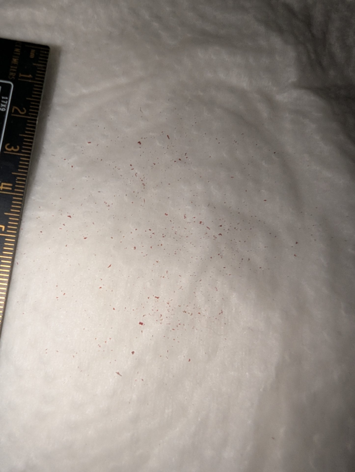
Because I was curious, I emptied out the first gross particulate filter to see what I caught.

It's tough to see, but it is not much.

1738982536695.jpeg


That speaks very well for Watercool and their manufacturing process for these things.
 
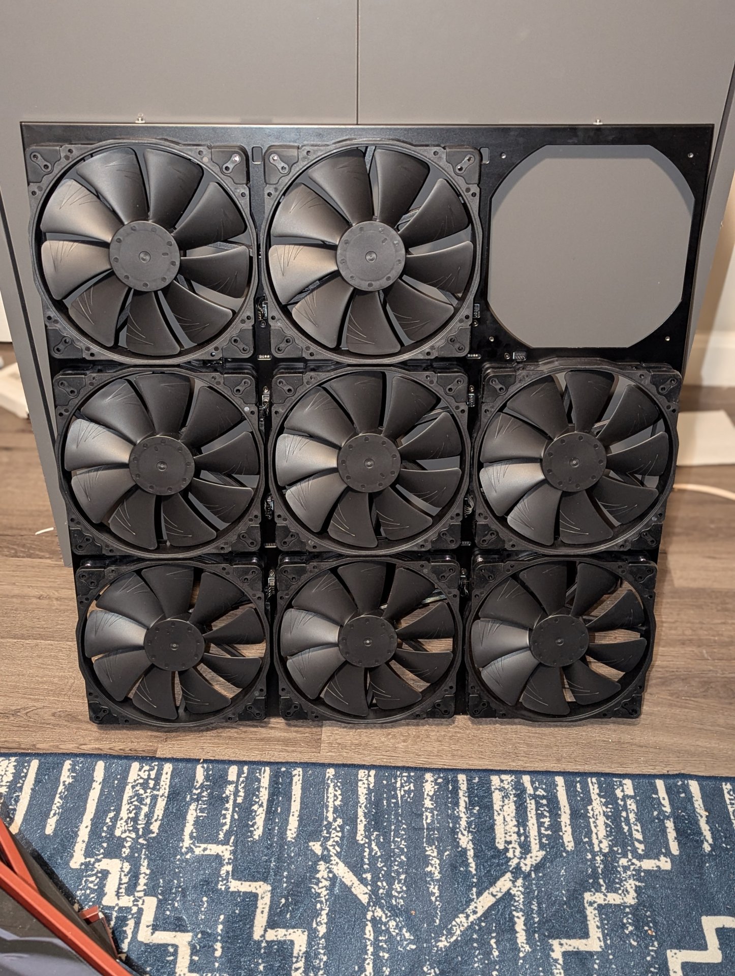
Well, it took all night, but I got the rack rearranged, holes drilled for the second radiator, mounting brackets mounted, and radiators test fitted.

I had almost forgotten how much of a pain in the ass cage nuts can be.

Almost.

1739091789705.png


I wonder if that's enough radiator capacity. Might need to add some more? :p

Anyway, this took all night, and we are getting a whole lot of snow tonight, so I am going to be shoveling tomorrow.

Probably won't make much more progress on the project this weekend.
 
Well, it took all night, but I got the rack rearranged, holes drilled for the second radiator, mounting brackets mounted, and radiators test fitted.

I had almost forgotten how much of a pain in the ass cage nuts can be.

Almost.

View attachment 709516

I wonder if that's enough radiator capacity. Might need to add some more? :p

Anyway, this took all night, and we are getting a whole lot of snow tonight, so I am going to be shoveling tomorrow.

Probably won't make much more progress on the project this weekend.

Oh, and worth noting, I did go with the middle configuration from my spreadsheet screenshot above, but - obviously - the workstation and game box are not in there yet.

It looks like my concerns about eight distribution and stability were unfounded. The thing is still completely stable, even with two heavy UPS:es midway up, and a heavy 4U server above that and big empty spaces in the lower half of the rack.
 
I've run into another momentary setback.

I determined that ideally I should make my own fan cables for things to be clean and the right length.

Initially, since I have so many unused Noctua extension cables from the boxes and boxes of Noctua fans I have bought, the plan was to just lop off the existing fan connectors and solder them to my own cable (maybe using solder-seal joints) and then covering it all in one big heat shrink seal. It would have been a little janky, but I figured it would be making the best of what I have, so I don't have to buy crimpers, pins and make my own connectors.

I did some tolerance stack-up calculations - however - and I think that if I do this, there won't be enough space between the fan bracket and the radiator fins to fit the resultant bulky cables.

So I am going to have to invest in pins, connectors and crimpers. (Not sure if they use a specialty crimper, or if I can use my standard electrical strippers)

Going to have to do some research on what the right parts are, and what crimpers I need.

Edit:
Looks like I need the following parts:
Connector body: Molex 47054-1000, RS 720-5990*
Pins: Molex 47054-1000, RS 172-9178*

Still not sure if I need a specialty crimper though.

Edit:
*If you are coming across this later, I ordered the wrong parts a few times (for various reasons) but eventually got these connector housings, and these terminals.
 
Last edited:
I'm having a surprisingly difficult time finding these parts from anywhere a normal human being (without a purchasing department, or a need for reels of 10's of thousands of parts) can purchase these without serious ripoff pricing.

Some seller on amazon has kits of them with 5 connectors and exactly 20 terminals for like $7 each, which is a crazy price considering these cost pennies a piece. (also, having only exactly the right amount of terminals is a bad idea, as I know I will break some as this is the first time I crimp these)

We used to have this electronics store in the greater Boston area named "You-Do-It Electronics". They were amazing. Think Radioshack back in the day, but like 100 times the size.

1739475114967.png


Unfortunately they closed their store a few months back. They had been operating since the 40's. It was a huge loss. I could probably have found these parts there at non-ripoff prices.

I think the problem is almost no one DIY's electronics anymore, and that is a crying shame. We live in a "buy a finished device, then throw it out and buy another" era.

If anyone has any recommendation on sourcing of these parts in 100 or less quantities at non-rip off prices that sell to consumers, I'd appreciate it.
 
Digikey has the connector. Check out the "associated products" (not the "mating products") at the bottom of the page for the pins. The pins I looked at weren't stocked, but they might have some others.

https://www.digikey.com/en/products/detail/molex/0470541000/2405319

Edit: oh hey, here: https://www.digikey.com/en/products/detail/molex/0008500113/304071

Edit2: Also in pre-crimped assemblies (see assoc. Prod. on the pin's page for more): https://www.digikey.com/en/products/detail/molex/0008500113-12-B2/5987703

Thank you sir. I recognize the name digikey, but they were not in my "active vocabulary" of places to shop. I appreciate the reference and links.
 
As an Amazon Associate, HardForum may earn from qualifying purchases.
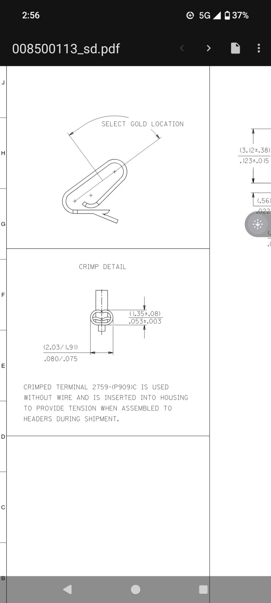
Looks like 080/075. It depends on the wire gage iirc, so whatever 22-30 ga wire diameter is, more or less. If you order from there, you can get 100 for $7, so you'll have plenty to practice with.


Screenshot_20250213-145618.png
 
Looks like 080/075. It depends on the wire gage iirc, so whatever 22-30 ga wire diameter is, more or less. If you order from there, you can get 100 for $7, so you'll have plenty to practice with.


View attachment 710496

Thank you.

I think I was slowly getting there on my own, finding parts, a crimper and learning about the correct crimp size to use, but this definitely sped things up, and confirmed some assumptions I was making and was a great help!

Appreciate it!
 
Thank you.

I think I was slowly getting there on my own, finding parts, a crimper and learning about the correct crimp size to use, but this definitely sped things up, and confirmed some assumptions I was making and was a great help!

Appreciate it!
No problem. Maybe double check to make sure that pin is the same dimensions as the one you were looking for, but it should be correct if they didn't make a mistake in their catalog.
 
There is so fucking Winning in this thread! I will just bow before you sir!. Subbed for sure. Keep up the good work
 
This crimp tool seems to be a better design, for a similar price: https://a.co/d/2DDEg9t

It crimps around the insulation part at the same time, which could be good or bad thing I guess. The big thing is the jaws move straight down instead of at an angle, which can make the job much easier and improve results. And it's racheting, if you like that.
 
As an Amazon Associate, HardForum may earn from qualifying purchases.
This crimp tool seems to be a better design, for a similar price: https://a.co/d/2DDEg9t

It crimps around the insulation part at the same time, which could be good or bad thing I guess. The big thing is the jaws move straight down instead of at an angle, which can make the job much easier and improve results. And it's racheting, if you like that.

I looked at a couple of ratcheting crimpers first, but when I dug deeper into it, I found nothing but negative comments about them.

People were saying that they tend to break the terminals by over-crimping.

Especially the ones that try to crimp both the conductor and the insulation strain relief at the same time.

The conclusion I came away with was that simple crimpers that do one at a time might be a little bit more work per terminal but that the success rate should be much higher.
 
As an Amazon Associate, HardForum may earn from qualifying purchases.
  • Like
Reactions: Nobu
like this
I could use a little bit more crimping advice, if anyone has any.

Nobu ?

First off, bear with me, it's tough to take pictures of these tiny things (at least without breaking out the DSLR with the macro-lens, which I don't feel like doing right now)

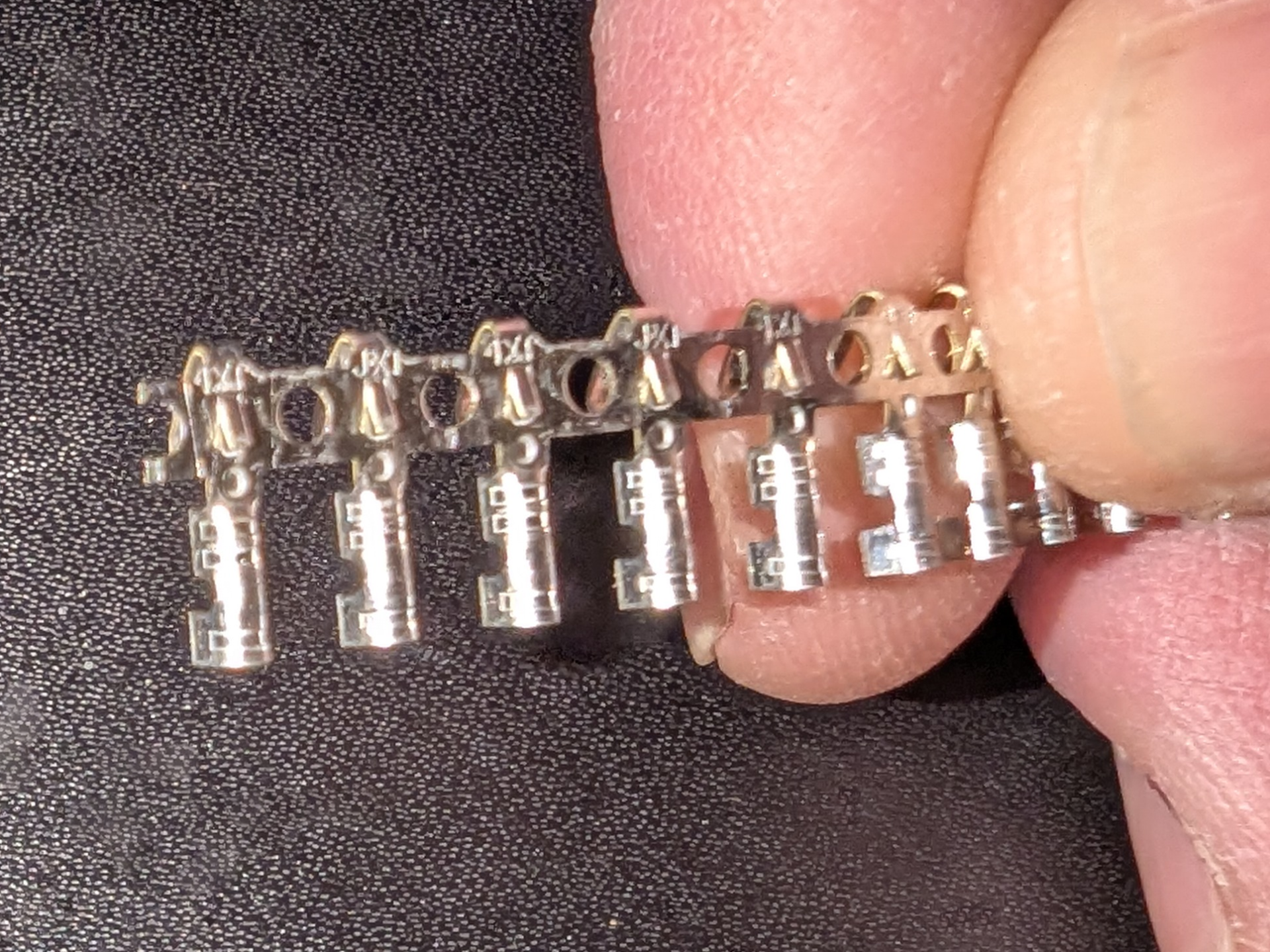
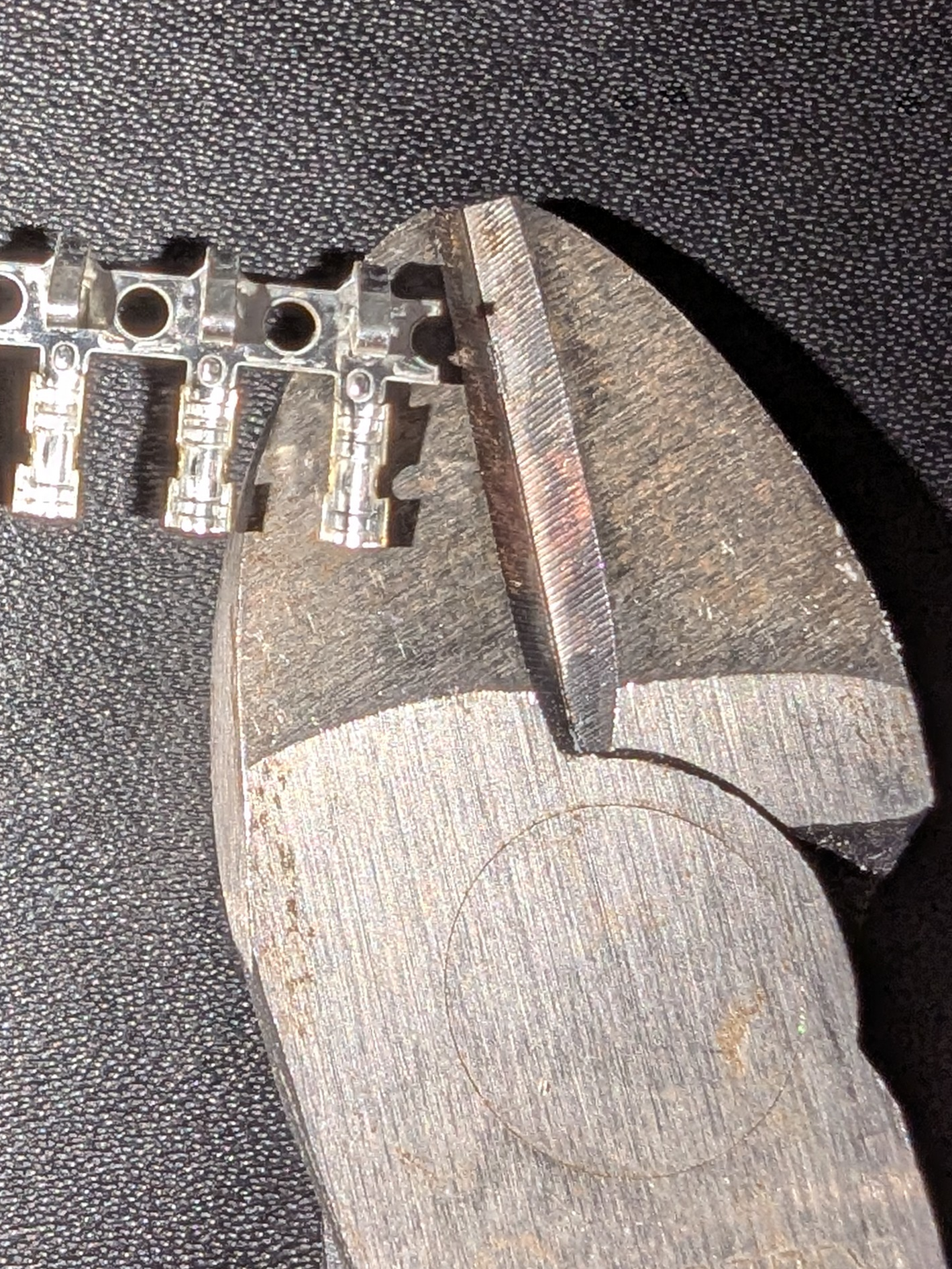
So, the parts appear to be correct, but they come on this strip:

1739936941825.png


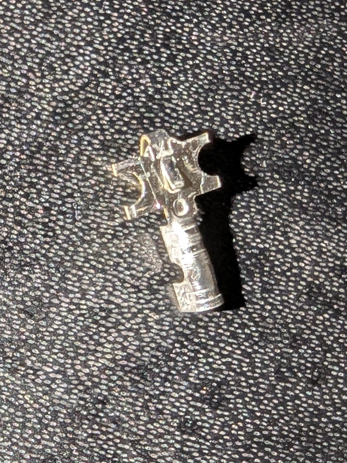
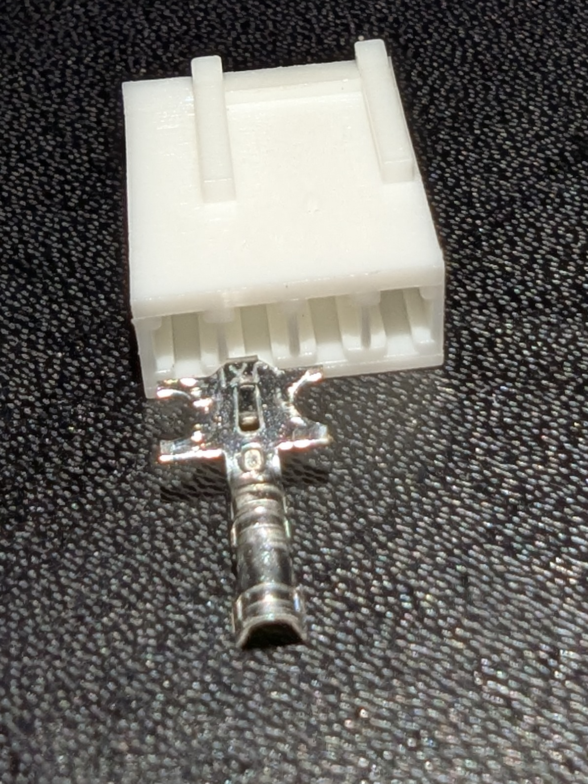
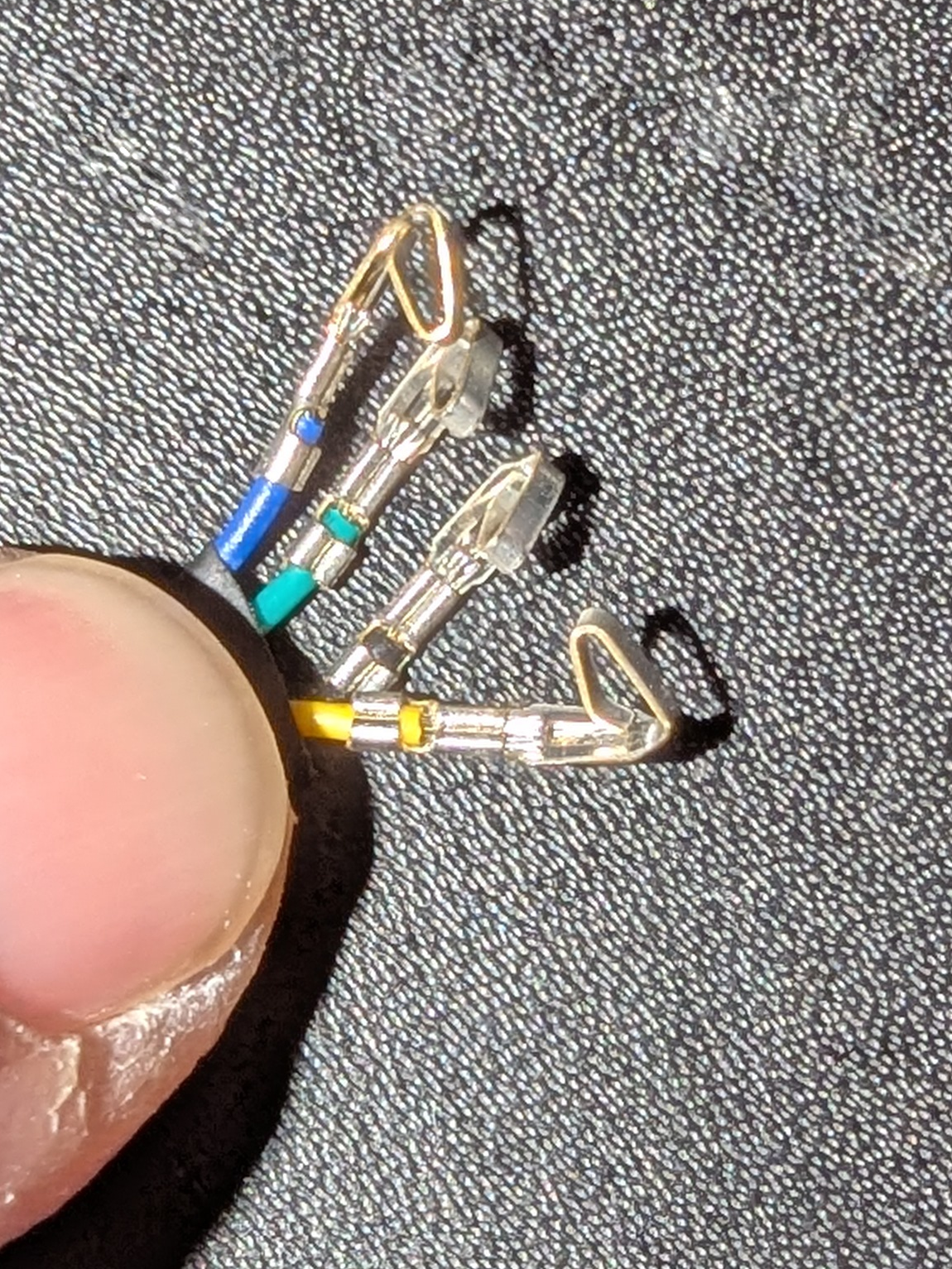
I've seen people just wiggle and break them off in the past, but then I get a terminal that looks like this, with "wings"

1739937076969.png


It's pretty clear that's not going to fit inside the connector body:

1739937346197.png


...but I didn't know what to do about them. Should I bend them into a square? Or wiggle them until they break off? Or snip them off with a cutting plier?


I removed the connector body from one of my many Noctua extensions for a reference of what they are supposed to look like when I am done:

1739937505158.png


...and the terminals in that thing look nice and clean cut.

Now here's the problem.

I tried grabbing them with the very tip of my needle nosed pliers (which are huge by comparison) and bending them back and forth, hoping they were designed to break off at the right place, but that didn't do the trick. That wound up just destroying the terminal.

Then I tried snipping the wings off of the terminal with a cutting pliers to no avail. It just mashes the shit out of the entire thing. The comparative size of my cutting pliers to the size of the terminal are probably a contributing factor.


1739937878545.png


Any suggestions?

I've looked for videos on YouTube, but in every last crimping guide video, everyone seems to start with a clean terminal with nothing attached.

I presume in volume manufacturing they have some sort of automated equipmet that feeds the reel into it, and then die cuts the terminal out after (or during) the crimp, but that is a luxury I don't have.

1.) Are the smaller, sharper cutting pliers I should try?

2.) Do I have the wrong terminals? (I mean, they are the right one, but maybe I got the ones for automated assembly, not for manual crimping?

3.) Any other suggestions?

I'd appreciate any input from anyone with experience with these things.
 
2.) Do I have the wrong terminals? (I mean, they are the right one, but maybe I got the ones for automated assembly, not for manual crimping?

Reddit suggests this is the answer. That I should have bought "loose terminal" parts.

I'm going to have to search around for those.
 
Back
Top