Project: mITX SFF custom case

grsychckn

Weaksauce
Joined
Jan 26, 2016
Messages
68
A few months back I started getting excited about Zen and Vega so I wanted to try something I've never done before. I began working on an ITX SFF case that would house a dGPU as well while keeping the volume as small as possible.

I began this project without knowing about the Sentry case, but decided to move forward instead because I both wanted to do some things differently and go through the experience of design to manufacture for myself.

I went to Michael's and bought some thick drawing board to first mock up a design in paper before translating it into CAD. These images are from the end of September and show the result of of the design I was able to achieve just sitting in my living room playing with dimensions and positions of components. You'll notice the mITX power supply I chose to use which later had to upgrade to a SFX when I realized I could only get it up to a maximum of 600W.

paper_1.jpg

paper_2.jpg

paper_3.jpg

paper_4.jpg

paper_5.jpg

paper_6.jpg

paper_7.jpg


Once I had this portion complete, I started learning SketchUp so I could design the case and export it to the machine shop for their punch machine to manufacture. After I had the design complete in SketchUp, I added a placeholder for the SFX power supply as well as a USB 3.1 Type C 20-pin board and a wireless LED RGBW controller board. The plan is to install the custom RGB LED strips inside the case and have a custom front-panel RGB button.

At this point, I had decided to make the dGPU face "up" so the fans would be oriented in the same way the CPU fans were. This way, I could configure the case in either a vertical or horizontal configuration and not have to worry about airflow. Another change I made was to allow the case to be mounted to the stand on either the "top" or the "bottom" face so that the user could decide which way they wanted the vent panel to face.

I added a 4mm panel without vents to provide strength as well as a cover for the "mounting" panel so you can easily access the underside of the mainboard as well as the SSDs.

itx_case_1.jpg

itx_case_2.jpg

itx_case_3.jpg

itx_case_4.jpg

itx_case_5.jpg


At this point I sent the design to the machine shop who immediately threw it back to me because SketchUp's IGS format converter did a lousy job of converting SketchUp's surface format. At this point, I purchased ViaCAD Pro and remodeled the entire case from scratch so I could send the case file to the machine shop.

As far as the power button, I decided I wanted something much different than usual. I started by looking at Alibaba to find what buttons manufacturers offer that also provide LED lighting. I stumbled upon Piezo switches that seemed to provide me with something unique. Piezo switches have no moving parts (similar to capacitive switches but without a power requirement). After ordering a sample, the LEDs were fine, but the button operation was momentary only - you cannot "hold" the switch in the off position. Therefore, this button style wouldn't work and I started running out of time to have these by the end of the year. Below is a picture of the sample Piezo switch I ordered.

piezo_switch.jpg


I eventually settled for a standard button in a similar style with RGB LEDs.
standard_switch.jpg


After the machine shop asked me to make a few tweaks, I modified the base to simply have 4 angled feet so I could get a prototype done, but I'll probably modify the base again before making the final product.

Specs
Internal Dimensions: 304mm x 68mm x 350mm (7.23L)
External Dimensions: Unknown (will depend on metal thickness)

1 x standard ITX motherboard mount
1 x PCIe dGPU with maximum length of ~304mm
4 x 2.5 drive mounts (if I decide to make adapter plates they could be stacked to support up to 16 drives without a dGPU)
1 x SFF Power Supply (Using Lian Li 750W to mock up mount plate)
1 x USB 3.1 Type C connector (front panel)
1 x USB 3.0 Type A connector (front panel)
1 x Wireless LED controller with phone app to adjust RGB color

No optical drives

For a lot of the parts I had to order them in quantity so it is possible that I will be making these for sale at some point. I'll be updating this thread as I make progress. Currently I'm waiting on the machine shop to make the first prototype which should be done by the first of the year. BTW, the prototype will be done in aluminum which I plan to use unless it proves too weak to support the weight of the components. I will then finish off the main portion of the case by blasting the aluminum to have a "macbook"-like finish and I'll paint the thick side panel and base a bold color.
 
That is awesome. I am doing something similar but instead of a case I am wall mounting it. I look forward to seeing the results.
 
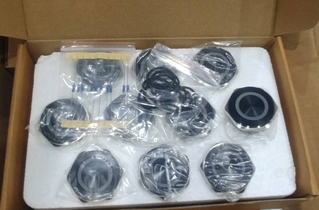
The buttons arrived yesterday and I got a chance to test one out. Ignore the scratches on it, the box was damaged and this one was the only button with scratches so I used it to test. I plan on media blasting it to see if I can change the finish. I'll be sure to use media too large to fall into the button.

RGB_button.jpg


Note that in person the colors are more rich. For whatever reason, the video washed out the colors. It is pretty cool though to use the app on my phone to manually control the colors of the button or specify a function to change colors on a period (RGB color cycling set in the video).

I had to purchase 20 buttons so it looks like I may be making approximately 20 of these depending on the prototype which should be coming in the next 3 weeks or so. Updates will come when I get the prototype for sure.

It will be neat to see the RGB LED strips inside the case coordinated with the button.
 
I would be interested to see some more pictures of the switch, specifically the back. I have a ASUS mobo with RGB headers built in and I think adding one of there to my case would be something I would do.

Prototype looks sweet!
 
I would be interested to see some more pictures of the switch, specifically the back. I have a ASUS mobo with RGB headers built in and I think adding one of there to my case would be something I would do.

Prototype looks sweet!

I'll try to get a picture of the back tonight. Unfortunately, the buttons are dual-pole so there are 2 switches each with 2 pins (4 pins total). I also had to order the RGB-LED wiring to be common positive (+) and each individual color has it's own ground (-) wire because that is what the LED controller requires.
 
I'll try to get a picture of the back tonight. Unfortunately, the buttons are dual-pole so there are 2 switches each with 2 pins (4 pins total). I also had to order the RGB-LED wiring to be common positive (+) and each individual color has it's own ground (-) wire because that is what the LED controller requires.

Sounds good, thanks for the info. The RGB having the common plus three other connectors is no big deal, that's actually how the RGB header on the ASUS mobo works.

You'll have to forgive my lack of knowledge on these switches, but does it being a dual pole effected it's ability to operate as a power button for a computer? My understanding is that each pole is independent from the other, but the switch will actuate both poles at the same time. Also would the switches you have still allow one to use the "hold" function you would use on a computer to do a hard shutdown?
 
Sounds good, thanks for the info. The RGB having the common plus three other connectors is not big deal, that's actually how the RGB header on the ASUS mobo works.

You'll have to forgive my lack of knowledge on these switches, but does it being a dual pole effected it's ability to operate as a power button for a computer? My understanding is that each pole is independent from the other, but the switch will actuate both poles at the same time. Also would the switches you have still allow one to use the "hold" function you would use on a computer to do a hard shutdown?
I'm going to test that tonight as well with my multimeter. My understanding is that one set of pins is Normally Open (NO) and the other is Normally Closed (NC). I should be able to use the NO pins to wire up a power switch and it *should* stay in the switched position as long as the button is held down - I ordered these because of this reason as the Piezo switches were only momentary.
 
I'm going to test that tonight as well with my multimeter. My understanding is that one set of pins is Normally Open (NO) and the other is Normally Closed (NC). I should be able to use the NO pins to wire up a power switch and it *should* stay in the switched position as long as the button is held down - I ordered these because of this reason as the Piezo switches were only momentary.

I don't have a picture, but I did test the functionality of the push button with a multimeter and it behaves as I expected. Two of the 4 pins are normally open and whenever the button is pressed, it switches to a closed circuit (for as long as the button is held). The other two pins behave the opposite (normally closed, then open when pushed).
 
Looks cool.

Thanks! Thought I'd update with the latest iso view and the new base. The machine shop has the template done for the punch machine except for the PCIe tab cutout. That's proving to be a little bit of a problem but nothing too bad.

itx_case_rounded.jpg
 
Update: The machine shop finished the initial punch map for all 5 pieces.

punch_map_part_a.jpg

punch_map_part_b.jpg

punch_map_part_c.jpg

punch_map_part_d.jpg

punch_map_part_f.jpg


We discovered that the video card "tab" is going to be quite difficult to make consistently so I had to create a new part that will require the video card screws be mounted in reverse from their normal position. Below is the updated part I created. I'm hoping that in the coming weeks I'll have the prototype in my hands for final tweaks.

itx_pcie_new_option_4_small.jpg


I'm going to be out of town for a week but when I get back on the 16th, I'm going to try and play with finishes/paints on my buttons. I'll update with images when that is complete.
 
Checking in to report no updates except that I might not need the altered video card tab. The machinist is going to try and use a "stitch" to make the bend. I'll have to wait and see how it turns out. Currently, my project is in the holding pattern until the he has time on the punch machine. As I understand it, his company is currently using the machine 24/7 for large orders.

He did inform me that he is going to try to use 14ga aluminum (~1.5mm) for everything. This would reduce the overall external dimensions to around: 307mm x 72.5mm x 354mm (7.23L)

What I have purchased since the last update:
20 wireless LED controllers
1 5050 RGBW LED strip (5m)
10mm RGBW connectors (both '+' and 'L' adapters)

For an additional project I've purchased a few CPU waterblocks, pumps, reservoirs, and tubing. The idea will be for an even slimmer case when raven ridge (APU) is released and the objective will be to build in watercooling (probably just a single 120mm radiator but I might go with something more "custom"). If I manage to make and sell all 20 of the cases above, I will definitely be making enough of the smaller "HTPC" cases to sell as well. Good news is that most of the legwork for parts and sourcing will be done by then.

Hopefully I'll have some images to share from the machine shop this weekend - I'm feeling lucky.
 
Looks like I wasn't lucky. Still waiting for machine time apparently. At this point, I feel I'd be lucky to get the prototype before Ryzen releases. The reason it's worth the wait is because of the price and service my contact is providing for me.

Other purchases I made this week: Paint (2-stage clear matte, base, and primer), 16GB TridentZ RGB DDR4 3866 RAM, and 512GB Samsung 960 EVO 500GB m.2 drive.
 
Update: The machine shop made the first prototype. It has some bend issues and even though he thought he solved the problem with the video card tab he later discovered there's still a problem with that bend. We're going back to the drawing board for that problem. I may try to get the video card holes/tab made as a separate piece that is attached post-build. it would give me 1.5mm more clearance for video cards and if removable it might allow for longer cards to be installed. Pictures below.

first_prototype_1.jpg


first_prototype_2.jpg


first_prototype_3.jpg


Also, I ordered both an R7 1800X and an R7 1700 from Newegg. Waiting for ITX mainboards to be released.
 
Update: Machine shop is going to ship the prototype case this week so I should have it in the next 4-5 business days. There are changes to make already (mostly the small vent holes) and the shop admitted the prototype has a few deformations but they are sure they can solve those problems on the next one. I'm sure there will be a few new ones as well once I can mount my test system. I'll be sure to post a lot of pictures once I receive it.
 
Received the prototype last night and already started making adjustments to hole locations and fixing bad measurements. Below are two pictures comparing the size (without stand) to an Xbox 360 Slim and the final picture is showing my test-fit components laying inside to give an idea about layout.

itx_prototype_testfit.jpg


itx_prototype_size_1.jpg


itx_prototype_size_2.jpg


Some interesting things of note:

1. I'm going to have to lose one of the SSD mounting locations if the wireless LED controller is installed (I took a measurement for the power supply from a smaller SFX unit I have and failed to take into account the larger size of the Lian-Li 750W unit I plan on using). Good news on that front though is there looks to be approximately 1" of clearance between the disk mounts and the video card so perhaps I'll make some brackets up to mount 9-12mm units piggyback style to double the possible storage.
2. The tab we decided to use will work and work well. Right now I've got a smaller 5770 card held in place using just the mounts on the back of the case. I'm not really too worried of structural problems after I add the PCIe mount.
3. The power supply mount will have to move a few millimeters as it interferes with the front button. I'm going to mock up the internal power extension cable and see exactly how much clearance I have to adjust.
 
Well, all my measurements were right, but the power supply I have in the picture above is wrong. I forgot that I decided that power supply was not going to be used in the final case because it is too long and interferes with the front button. Instead, I've purchased the 600W Corsair SFX power supply that is just over a whole inch shorter. I also took a picture of the prototype sitting inside my current case (Corsair 750D).

ITX case inside Corsair 750D
inside_current_case.jpg


Picture of components mounted (290X video card)
prototype_with_components.jpg


Lastly, I made a video on how the video card will be installed and removed
 
Update: Just received my PCIe-Extender cables. Also confirmed my machine shop got the prototype back with my notes so they will start working on the changes I requested.

pcie_extenders.jpg


This reminds me that I wanted to give a breakdown of the cost of the components I plan to put inside each one. This should give an idea that I won't be making anything off of selling the extras but it helps with things like the buttons which had a required minimum purchase quantity.

Custom LED Buttons: $20/each
Wireless RGBW LED Controller: $15/each
LED RGBW light strip: $15/each
EZDIY PCIe Extender cable: $30/each
USB 3.1 Controller: $15/each
Thumbscrews (8-12 required for each case): $2.25/each
Power Cable Extenders: $2/each
Power Switch Panel: $2/each
Fan Fitler material: $10/each

Plus there are all the random parts & pieces like screws/standoffs/paint/wire management/heatshrink/etc. Just the items above will total around $127, and that's not even counting the case or the power supply. Not to mention my time to assemble, paint, and purchase/acquire packaging. I've been trying to target around $150-200/each without a power supply so once I get the final design and prices from the machine shop I'll have a complete picture of how much it costs to make just one unit.
 
Update: My machinist is out of town until Sunday but he said he hopes to get the next prototype done and shipped by the end of this coming week.

In the meantime, I purchased a large sandblasting cabinet from Harbor Freight and tried blasting a few buttons I had lying around to see if I like the finish. I definitely like the finish (I'm using very fine glass beads - 170-200 grit) but I'm unsure if I'll be able to make large areas consistent enough to not look splotchy. I'll have to wait and try it on the prototype when I get it. I'll definitely have to sand out larger scratches before I blast though as they will show through.

I tried on 3 different buttons and one piece of angle aluminum. The first two buttons are Piezo switches I purchased in hopes I could use them because of they have no moving parts but unfortunately they are only momentary on even if you hold pressure on it.

Button 1
sb_button1_before.jpg


sb_button1_after.jpg


Button 2
sb_button2_before.jpg


sb_button2_after.jpg


Button 3 (actual "sparkle" is somewhere in between last two pictures)
sb_button3_before.jpg


sb_button3_after.jpg


sb_button3_after_daylight.jpg


Angle Aluminum (you can see the unblasted finish on the bottom and the blasted part on the top
sb_angle_1.jpg


sb_angle_2.jpg
 
Last edited:
Quick update: Running a little behind on getting the next prototype case. The machinist is really busy but apparently has just finished punching and bending the new case. He has some good ideas that might help make the case stronger but might also impact the compatibility for video cards. Either way the new expected ship date would be sometime next week due to the changes we've made. In the meantime, I bought a 2-layer stencil to try painting a logo on the solid panel.

ryzen_stencil.jpg
 
Wanted to update this thread as a "keep alive". Looks like the second prototype required more changes but I've seen pictures of it so I know it exists. The machinist was very excited about the build quality of this one as well as the time it took to build compared to the first. Updates coming as soon as I get word on shipping.
 
Ok, finally got the second prototype and I'm please with most of it but there are still a few niggling issues to deal with. I'm going to start with pictures of the case after I bead blasted the panels and the button.

prototype_2_9.jpg


prototype_2_1.jpg


prototype_2_8.jpg


I'm currently trying to get the side panel and base painted so I can present something that will be a little more polished. Below are a few of my attempts at painting the side panel using the stencil from above. I have to repaint them both however because I didn't wait for the primer to completely dry before painting and so the paint cracked and about 90% of it peeled off overnight. I then re-sanded and painted the primer to leave for overnight and this time it stuck very well to the panels. I should have another update this weekend with the panels painted and installed.

prototype_2_6.jpg


prototype_2_7.jpg


Below are the only major issues left to address. The first is the bad fit on the seams at the top and bottom of the front panel. I've got a suggestion in my mind that should help resolve this issue. The primary problem is that I designed it to be one sheet folded such that it has 5 surfaces and thus the bends are quite tricky to get right.

prototype_2_2.jpg


prototype_2_4.jpg


These show the base which has one leg longer than the other to compensate for the top/bottom not fitting right.

prototype_2_3.jpg


prototype_2_5.jpg
 
Ok, go easy on me for what I'm about to post. I painted the large panel and base again but this time I let it dry before laying down a new coat. The problem right now is that I had to paint it outside on a windy weekend with pollen so thick in the air it was like a dust storm. Therefore, both the base and the clear coat have lots of debris trapped in them. Because this is only a test to show what the case could look like, I didn't bother making sure I was in a clean environment and the results show. Also, I was sloppy with the stencils until I learned some tricks to get them working OK. I'll still have to do some work on that once I get in the next iteration.

First panel with metallic orange and red paint
paint_test_1.jpg


Second panel with flat orange and red
paint_test_2.jpg


3/4 views
paint_test_5.jpg


paint_test_3.jpg


paint_test_4.jpg


Both test panels and bases
paint_test_6.jpg


Ok, I thought the second one would be the final prototype but after a long discussion with the machinist on Saturday we identified some things that need to change. First, the seams need to fit better. Next, the video card slots need location adjustment. I still have to test the USB front panel fitment and make adjustments. The machinist is confident he can recreate with accuracy the base (fixing the one leg longer than the other problem). The fasteners for the large panel were not installed - I tapped those myself. Also, the large panel and the vent panel will need to be a little bigger as we decided to add some bends to the front and rear panel for support.
prototype_3_new_bends.jpg


If all goes well, I should have the next version to me in 2 weeks or so.
 
Let us know what the cost on one of these is when you have it finalized! Really awesome looking case!
 
Let us know what the cost on one of these is when you have it finalized! Really awesome looking case!

Absolutely, you prefer a PM? Currently I'm at least a month off from having the first lot made, but will keep this worklog updated with progress.
 
Update to say I'm getting on a plane Friday to visit with the machinist in person and hopefully we'll at least finalize the design this weekend if not make all 20 units. Expect an update next week with videos, pictures, and more info.
 
Quick update with some new pictures. I think we got nearly everything done this weekend but I left the USB adapter at home so we've got some adjustments to make there. I'm hoping I get one more prototype made before I can order the batch. I didn't realize how much work goes into setting up the equipment and reconfiguring them just to make the process smooth.

machine_shop_1.jpg


machine_shop_2.jpg


machine_shop_3.jpg


machine_shop_4.jpg


machine_shop_5.jpg


Note that we got the seams to match up great and even the video card lines up perfectly. I've got some videos to upload tonight so I'll be making another post later with those.

Edit: With one of the many we made but scrapped, I put it on the floor with the vented panel on top and stood on the front and rear edges. It supported all 200lbs of me so I feel pretty good about it's durability. I'm sure it wouldn't support a lot of weight in the middle as there's no support but putting a monitor right on top would be silly anyway since that's where the vents are for cooling.

Edit 2: I also finally purchased 2 Biostar ITX boards for my Ryzen 1700 and 1800X CPUs.
 
Time for another update. I've been very busy at work and home so this project gets what time I have left which isn't as much as I'd like. That said, I have been quietly working with the machinist to get the final punch map finished so the next time he is able to carve out a block of time, I've requested he make my first run of 20 units. It might not be as perfect as I'd like and I'm sure there will be some things I'll have to hand finish, but once I get them in my hands I'll be in full control.

That said, I took some time to work on the LED lighting of the case the last few days and I really like the results. I don't like the size of the LED strip lights I purchased but they are a standard size and light up the case really well. I'm partially torn though because I found I left only 10mm tolerance for the LED strips and the snap connectors are 12mm so they interfere with the PSU which means I'll have to solder the connectors if I want to offer them pre-installed. That alone will take FOREVER as there will be at least 30 joints on each case to solder if I keep the location of the LED strips as they are.

The other annoying thing I discovered is that the RGBW strip lights I purchased seem to have the green/red leads backwards. My wiring follows the +RGBW label on the strip and my front-mounted button wires are correct (RGB). I noticed it when I was in the phone app changing the colors from green to red when debugging why the button LED was a different color than the strip lights but only when I was on green and red. Bizarre. I also had a problem with the front-mount button as it appears the red LED won't drop below 50% brightness when a lower value is used from the LED controller. I tried a few buttons and they all behaved similarly. I can fade the red from 256 down to 0 and from 128 to 1 it stays a solid color. This explains why the button appears to be out of sync with the LED strip lights in the following video.


BTW, the top of the case in this video does not have screws holding it in place - that is why you'll notice a gap up there. I've got to widen the holes on the top to allow screws to line up (already addressed on the latest design). When tightened down, it fits snug.

I haven't posted a picture of the inside in a while but I'm now using the Ryzen 1700/Biostar ITX combo and have begun wiring it for power. I'm going to work a little more on the LEDs this weekend and then I'll hit the power cables and address the last of the fitment issues on this prototype case so I can have a running system that best represents the final product before actually receiving them.
 
I've never been a huge fan of LED lighting all over my cases, but ignoring that: I'm impressed with your design here. Top notch, looking forward to seeing what comes next.
 
I've never been a huge fan of LED lighting all over my cases, but ignoring that: I'm impressed with your design here. Top notch, looking forward to seeing what comes next.

Thanks! The LEDs are controllable through a phone app so you can leave them off if you want. I was thinking that I might not include the LEDs installed on each one as it appears I have no option but to solder them together myself (30 connections per case) because the snap connectors are just too big to fit in with the PSU.

I'm currently in the holding pattern again for the machinist's time. However, I did tell him to go ahead and make 20 units when he's ready. I could easily see this being a few weeks though before I get anything from him.
 
4th of July weekend Update: I've decided to switch machine shops. The guy I was using does great work and does it cheap but because he does it on the side he doesn't have the time to produce a large number of units. Therefore, I found a shop about 1.5 hours away from me to produce the case. They specialize in making electronic enclosures for GE so they also have a wider range of fasteners available. Needless to say, this set me back several weeks in getting the first run made but once the new shop gets the drawings done, he's going to put me in the production queue as a customer. The cost will go up, but he can do things like offer power coating, more material selections, and Q&A. In the long run I think it will be worth the extra money to produce a higher quality product. Plus I don't have to worry about freight shipping the final products.
 
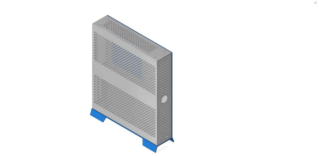
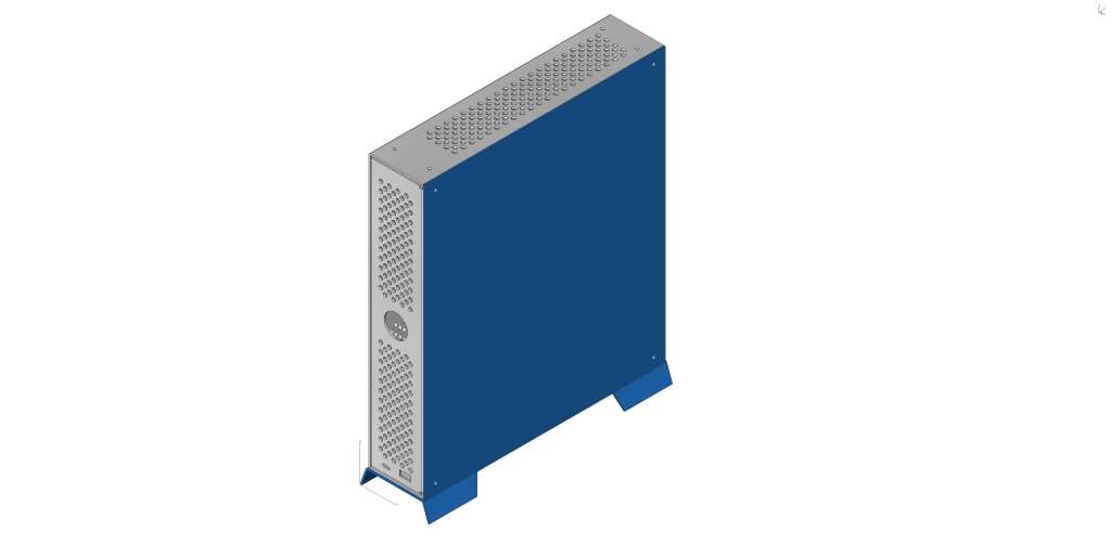
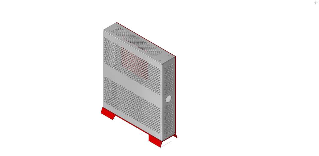
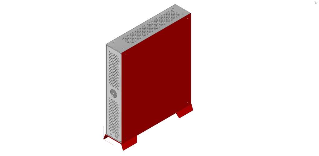
Renders of the case with different color panels for the side and base.

gray_blue_right_sm.jpg


gray_blue_left_sm.jpg


gray_red_right_sm.jpg


gray_red_left_sm.jpg
 
Last edited:
Update: Today the new machine shop is going to cut a sample using their water jet machine so I can test if the model I gave them is correct. Any alignment issues I'll adjust for and then give them the go-ahead to start production. I probably won't be able to test fit things until next week sometime.

On a side note, I found a source for an illuminated black button just like the stainless ones I already have and they are half the cost. This means I'm gong to also be producing black cases with the appropriate hardware as well. Currently I'm looking at having around 40 units made with half in silver, half black. I've decided to have the "core" pieces both powder coated instead of using bead blasting to finish them. This will be one less thing for me to worry about after I pick them up from the machine shop as they can powder coat as well. I'm not sure how I'm going to handle the side panel and base pieces as I want to provide a color choice and have them be powder coated but varying colors will be expensive as they'd have to be done piecemeal.
 
Machine shop has all the prototype pieces cut with the water jet. They will bend them and then I'll have an update with yet more pictures in the next week. For now, I wanted to post the pictures of the thumb screws I purchased for the side panel and the led light strips that I'm going to include as an option.

This is over $500 of thumb screws. Notice all the black screws - Since I found a source for the black button, I bought the black thumb screws to go with.
thumb_screws.jpg


Here you see 6 sets of LED strips (1 for top and 1 for bottom, length is different). This is 180 solder joints on 22AWG wire.
LED_strips_1.jpg
 
  • Like
Reactions: Derf
like this
I drove to the machine shop Friday and got the first prototype from the new shop. It looks fantastic but yours truly made some measuring mistakes when I converted my drawing into Solidworks. The motherboard mounting holes are too close to the back panel, the PCIe mounting tab is too short, and the standoffs for the USB card are too high. I've finished making the adjustments to those and have just resubmitted the drawings to the shop this morning. They say they can have a new one bent up this week so cross your fingers as I'm ready to get the batch made.

I also ordered a small powder coating oven and a dual-voltage gun and about 8 different colored powders including a nice chrome. I think I'm going to have the shop powder coat the cases either the matte silver or satin black and then I'll powder coat the side panel and stand (extra charge for multi-layer painting). As it stands right now, the units I'll try to sell to get some money back are going to probably be in the $300 range. It takes about $250 just to make the case, then I have the extra expenses of the buttons, LED controller, USB card, LED lights, screws, paint, shipping and shipping materials. I've said it before but I'm going to lose money on each one I sell. Once I get the final prototype I'm going to post some high quality images here with the expected price and availability (due to me painting the side panel and stand, I'll have to limit the orders to about 5 per week). I'm pretty busy and don't want to over-commit myself. I may even throw in some extras for the first few orders.
 
  • Like
Reactions: Derf
like this
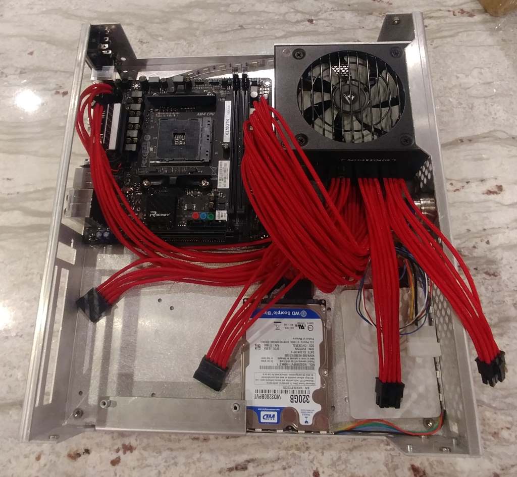
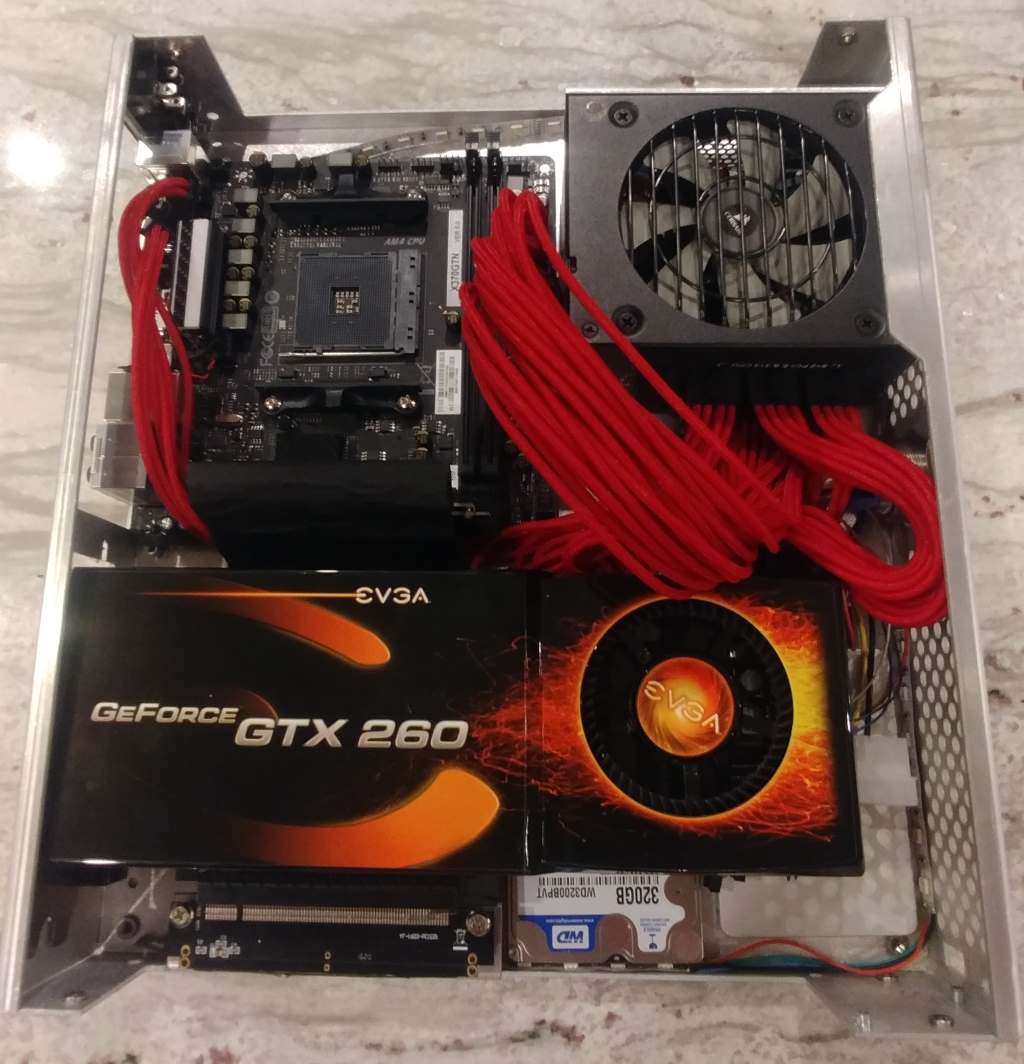
Ok, I sent the final drawings to the machine shop. I should have the first of the cases ready to go in the next 2-3 weeks. I bought some custom PSU cables for the Corsair SFX PSU I'm using so I thought I'd share the pictures. I obviously have some adjustments to make but since I purchased 3 sets (white, orange, and red) I'll have to find a way to make the cable management not a nightmare. I'm going to include a few cable management pads and a few zip ties to help but with cases like this there's really not much that can be done.

What you're looking at is ATX power supply cable, 4+4 pin CPU power cable, 6+2 (x2) GPU power cables, and 4xSATA power cables with a 3-pin (12V) lead for the LED controller. I'm thinking I can share my source for these or I can sell them with the case but it takes about 9 business days for me to receive them once ordered and will cost around $125 (~$100 if purchased from my source).

custom-cables-2.jpg


custom-cables-1.jpg


I also bought around $200 worth of powder paint which should give me a pretty good set of base colors to choose from. I also purchased a powder coating oven and gun which should be here by the end of the week.

As a side note, I reached out to Kyle to try and see if he'd be interested in me donating a case with Corsair SFX 650 PSU and 250GB 850 EVO m.2 drive with the [H] logo on the side. If you're interested in this please reach out to him as he's not responded to my PM yet.
 
  • Like
Reactions: Derf
like this
Back
Top