Gateless Majority Logic

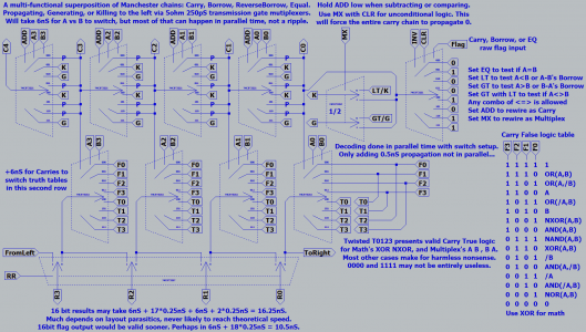
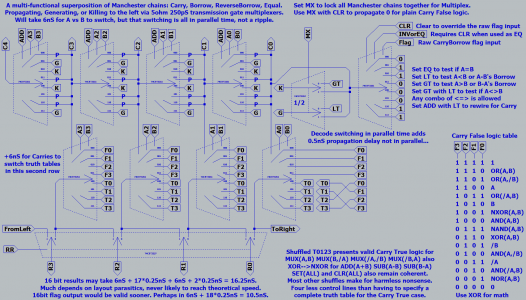
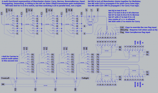
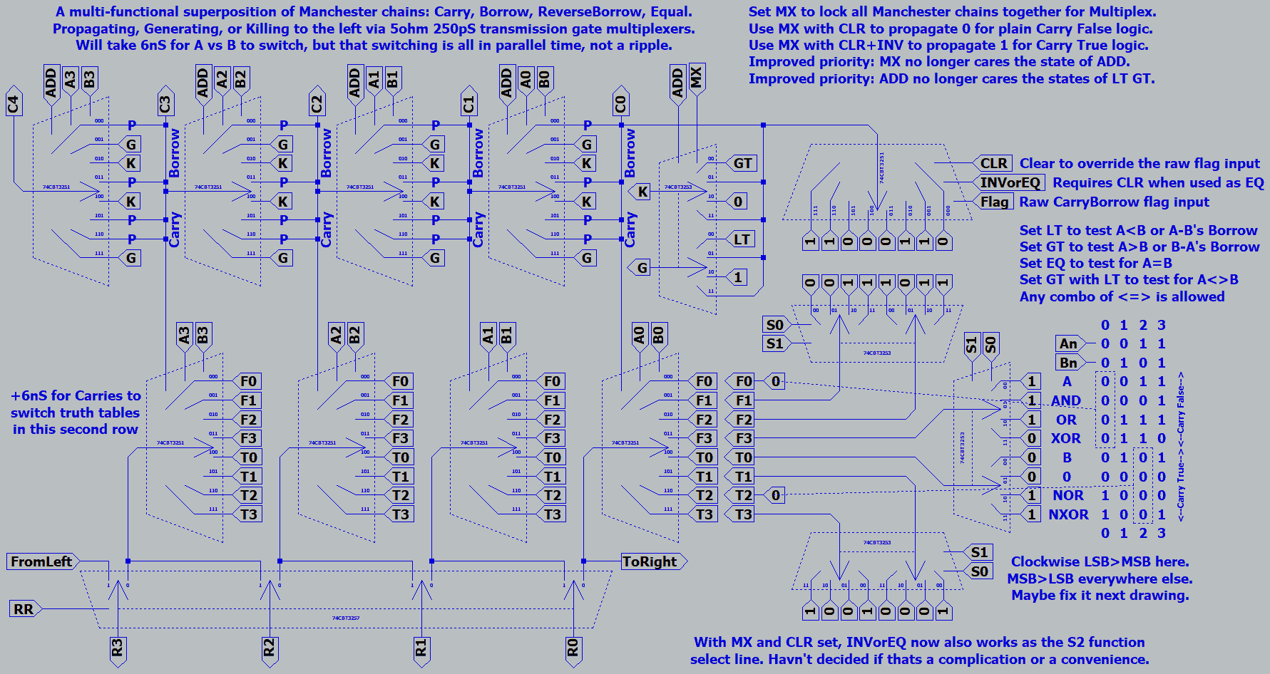
What it might look like if we chain 8 bits together for a full result...
Replacing two earlier drawings in this same post that had errors.
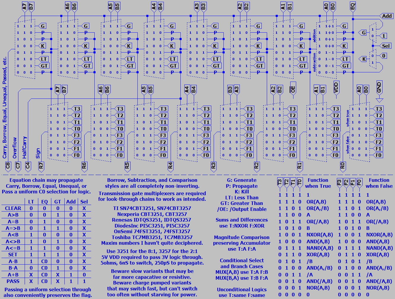
Fix20200918.png


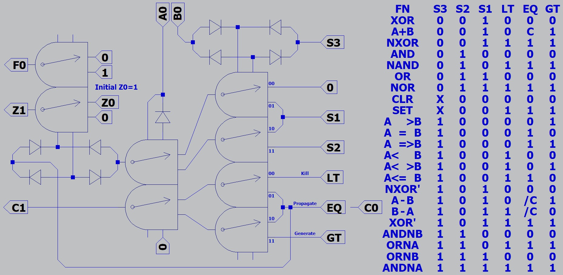
Trying here to make better sense of several earlier messes.
Changed "Inhibit" to "Kill" cause "I" looked too much like "1".
Changed "CarryIn" to "EQ" cause it made better sense of the new comparator functions.
"C" never made sense for Borrow, especially since I don't get there by add with inversions.
Selection of conditional logic now hijacks Carry rather than Borrow, cause it drew easier.
Four bits might fit a module of 32 pins with power and /OE, if I were to build it...
 
Last edited:
The ALU above merits a barrel shifter.

Barrel.png


Since switches can all be thrown while the ALU churns, the only delay is propagation through two transmission gates. 250pS each...

Note that only 6 devices are needed. Not requiring the braindead obvious 8 multiplexers, each sweeping through 8 steps of rotation.
Also consider the parasitic spaghetti factor. Only four dead-ends splay out per bit, instead of the expected seven. Expand to 16bits,
the low row of plexers would then become 4way as well. 6 dead-end sphaghetti vs 15 the dumb way.

The best way might be seriously wasteful of devices. Full spread from results to intermediate sphagettiland with no shared strand.
Then a full scrunch to rotated results. Why? Because unused strands cut from both ends cease to present unterminated stubs.
You might be surprised how much problem an unexpected inch long echo can cause...
 
Last edited:
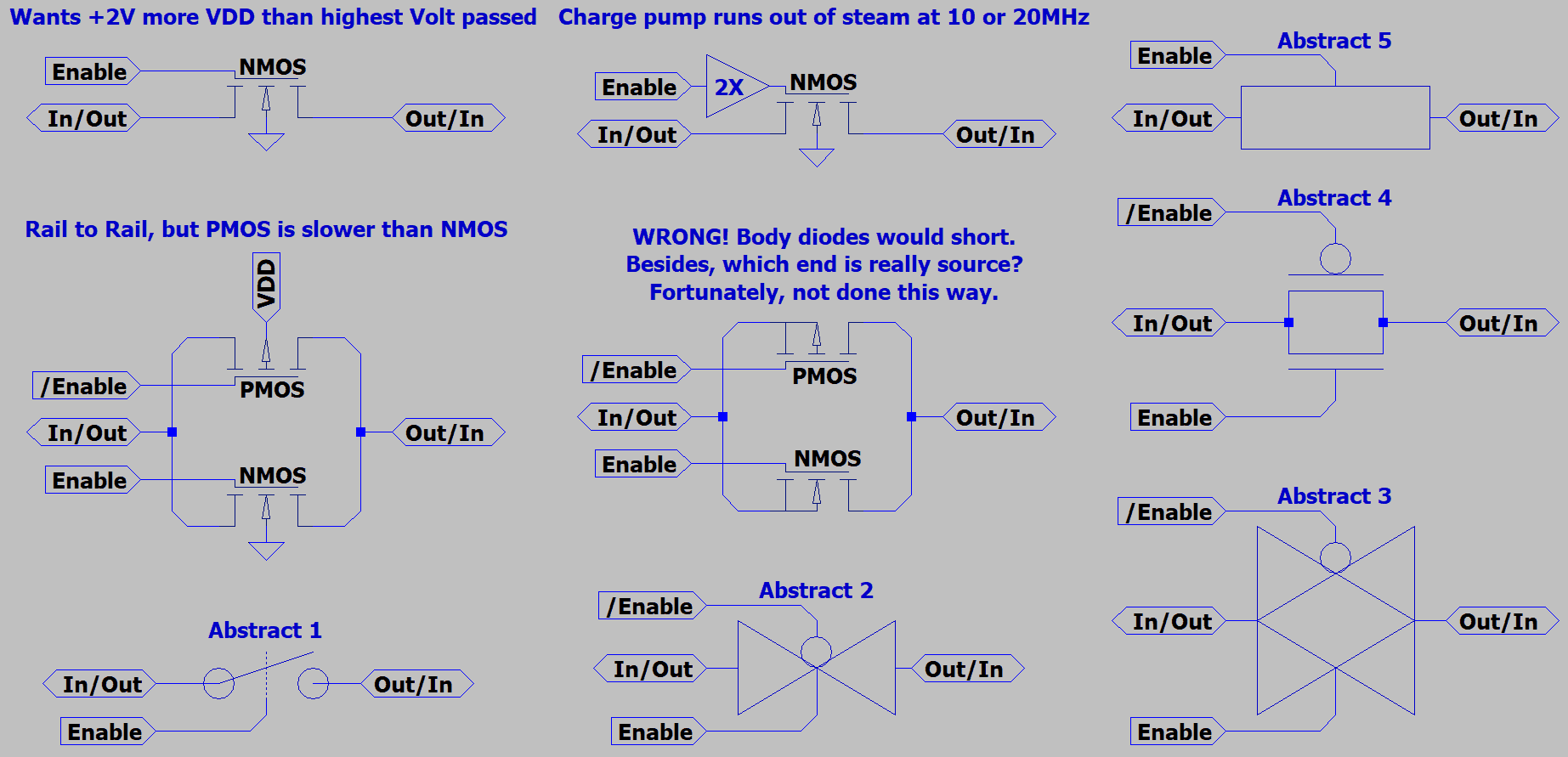
The offical name for these sort of switches would be "Transmission Gate". Below are
several common ways you might see them drawn in multiplexer spec sheets. Doesn't
seem to be much of an agreed standard across brands.

I was drawing them as-if relays. Overuse of that symbol ate too much space in my
drawings. Lately I'm drawing an abstract trapezoid to stand for a multiplex of several.
Somtimes I still prefer to draw finer details to explain some point or other.

Body diode given in the symbol for a stand-alone MOSFET would cause directional
leakage issues in a transmission gate. Fortunately, diodes in this situation connect
only to rails, not immediately to each source. MOS4 symbols I needed were already
in LTSpice. Just had to discover them.

TransmissionGates2.png


All gates are driven by internal pre-amps. Some amps offer protection features.
I didn't bother to draw all those amps, except the one case with a charge pump.
Just know they are there, and differ, and read your spec sheet before choosing.

Main gotchas to watch for:
74CBT needs VCC to be 2V higher than any signal you might want to pass.
74CB3Q has a charge pump, but power limited to 10 or 20 MegaSwitches/Sec.
74CBTLV can pass signals rail to rail, but PMOS isn't quite as fast as NMOS.
 
Last edited:
Always troubleshooting someone else's board, never designing my own...

I need some layout software with minimal learning curve that can handle 2 layers and SSOP16.
The place I work for uses Altium. But its overkill, and the licence fee is rather extreme. Plus they
don't want me hanging around off the clock to use a company PC with an existing licence.

So I will probably try: What is free tier Altium called, Circuit Maker? I gather you are forced to
openly publish your projects. And thats probably to prevent commercial misuse. Dunno what
other limitations. If its way different than regular Altium, the guys at work may not be able to
help me. Ultimately I need Gerber compatible files to have a board made...

The alternative is a crapload of 50cent DIP adapters and Vero Board. Which will get me there,
but isn't reproducible if I want to expand. And parasitic sphagetti might slow things more than
prove anything fast.

KiCad?
 
https://www.sciencemag.org/news/2020/09/short-weird-life-and-potential-afterlife-quantum-radar

"real entangled light pulses that experimenters can generate with a special crystal that converts a single higher frequency pulse to two entangled pulses at lower frequencies."
"Physicists can generate pairs of entangled microwave pulses from single ones using, instead of a crystal, a gizmo called a Josephson parametric converter."

Science news oversimplified to the point of nonsense. But sounds like Parametrons might have found a new use.

Recall the optical thingie of post #6. Keep in mind that an optical parametron excited by a single photon with no other logic input would generate a random binary phase shift.
Output at half frequency probably has to emit two photons for powers in and out to be equal. Returning strings of random key'd pulses may look like noise except when tested
for time and phase correlation to a copy kept locally in a delay line. It bugs me that radar would already have to guess the distance better than 1/4 wave before you could even
test wether there was a correlation. Or maybe thats why they are saying its 4 times better than regular radar? Not enough info here to be sure. I'm betting that light is not used,
but some really long microwave instead.
 
Last edited:
Another iron I got in the fire but can't exactly call gateless, is pre-computed lookup tables in parallel MRAM or NVSRAM.
As FPGAs interconnects a bunch little bit vs bit lookup tables. I'm simply interconnecting a few larger byte vs byte tables.
64 such tables will fit in the current largest 32 Megabit MRAM (21 bits in, 16 bits out), or 32 functions with result & flags.

Why bother? Same 35nS to lookup the third byte after the fixed point of a COSine(AB) as it takes to lookup AND(A,B).
If I homebrew an 8 bit minicomputer that only runs a few MHz, arbitrary cheatsheet logic will somehow have to make
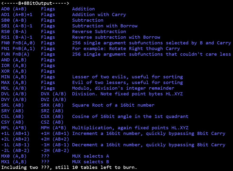
it impressive. So here's a proposed grand table of tables for the MRAM or NVSRAM that will serve as ALU. These are
just ALU functions, not instructions. IE: no jump to be found here. There will be another table to issue such microcode.

TableOfTables.png

I prefer to post as plain text, but forum won't tab and destroys spaced columns.
Not sure how forum "Insert Table" feature works yet, sounds promising maybe...

So, a pair of bytes found in the ALU table output to a pair of 74LVC373 latches.
Those latches then output to some, all, or none of three 32Kx8 register banks.
Couldn't find modern register banks smaller, cheaper, or less overkill than 32Kx8.
Register banks (together with microcode) form an address for the next ALU lookup.
Round robin in three steps, so input bits can be held valid while reading outputs.

First register bank serves the A argument.
Second bank serves the B argument.
Third bank (written bytewide, but read through an 8:1 MUX) serves the flag.
Completely ambidextrous, provided data was mirrored to all relevant banks.
Totally faking triple port memory on the cheap by throwing around extra copies.

Any bit stored to the 3rd bank can be indexed as active flag at a later time.
Test a non-flag bit from any result byte as-if it held flags? Fine, no problem.
Retrieve extra data hidden in unclaimed flag bits? Fine, no problem.

The first 256 bytes of register banks A&B should contain constants 00-FF. Perhaps a
routine at boot fills those volatile constants? Or spend the extra $5 and use an MRAM.
Either way won't need exceptions for indirect addressing. Just let everything be indirect.
Constants now imitate the missing direct mode.

Increment by +1 and +2 tables could serve as the program counter and skip next.
But I prefer the program count to be read in parallel time from a separate device.

Enough for now. We'll talk single argument tables when I got them in presentable order.
Good stuff: Binary Coded Decimal, Greycode, Cellular Automata, 16 Segment LED Font.
Maximum abuse of arbitrary cheat sheet logic...
 
Last edited:
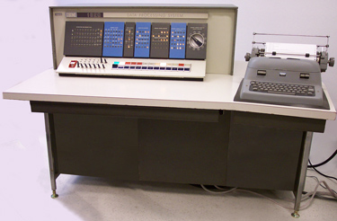
Strangely, this seems not to be a new idea at all.
IBM 1620 CADET "Can't Add Doesn't Even Try"
IBM_1620_Model_1.jpg

Abused both addition and multiplication tables
stored in non-volatile magnetic core memory.

Spintronic MRAM might then be Spin CADET?
Glorious...
 
Some explanation of single argument subfunctions is required.

Subfunctions will use the B input byte to choose the subfunction.
Operating only on the A input byte, and maybe the state of carry.
I'll replace text with a picture later to make the columns line up.
Gotta get to work now, so can't worry too much how it looks.

The chosen flag going into each ALU lookup may also be cleared
or inverted by two bits of each instruction. In this way the flag may
carry as normal, or select uncarried functions from either column.

We also have the option to discard either byte or flag result when
the other is irrelevant or distracting. This is used to combine similar
functions with different targets when one posssible target is carry.

Since subfunctions operate within the limits of one byte, N and M
shall represent bit positions within the argument byte and result.
C represents a chosen input flag. Carry, Zero, and six uncommitted
flag bits output together as a byte. Separated only when referenced
by later instructions.

Might let the uncommited bits hold inverse flags and 01 constants,
would trim two bits off my instruction width. Still mulling whats best.

Code:
# 256 Single Input Byte FUNctions
# ignoring Carry Input still allows for an optional Carry Output
------------------------
64      AND (N,M) to C,M # Only 56 instances matter
64      IOR (N,M) to C,M # Only 56 instances matter
64      XOR (N,M) to C,M # Only 56 instances matter
64      SWP (N,M)        # Only 28 instances matter
Code:
# 256 + 256 Single Input Byte Functions
# FN0 + FN1 with Carry Input, or as modified by the instruction
-------------------------- Functions requiring Carry input
64 + 64 AND (N,C) to C,M # Only 56 + 56 instances matter
64 + 64 IOR (N,C) to C,M # Only 56 + 56 instances matter
64 + 64 XOR (N,C) to C,M # Only 56 + 56 instances matter
        CPY   N   to C,M # Alias of AND/IOR/XOR(N,C) coercing C input
        CPY   C   to  N  # Alias of SWP (N,C) inhibiting the C target
8 +  8 SWP (N,C)
8 +  8 ROT   N   to  C  # Rotate through Carry until N arrives at C
8 +  0 SLL   N   to  C  # Shift Left  to Carry, fill void w 0's
0 +  8 SRL   N   to  C  # Shift Right to Carry, fill void w 0's
8 +  0 SRA   N   to  C  # Shift Right to Carry, fill void w Sign
0 +  8 CIR   N   to  0  # Circulate sans Carry...
2 +  2 R30              # Wolfram's Rule 30 with bookends CxxxxxxxxN
# useful for pseudorandom number generation
# https://mathworld.wolfram.com/Rule30.html
1 +  1 CNT  All     0's # Count All 0's may include Carry in = 0
1 +  1 CNT  All     1's # Count All 1's may include Carry in = 1
Code:
---Below this line, C input acts not as a flag but further selects subfunction---
0 +  8 CVT  ASC  to TRM # 8x8 Terminal Font (likely 5x7 plus a decender)
0 +  8 CVT  ASC  to CON # 8x8 Console  Font (likely 5x7 plus a decender)
0 +  1 CVT  ASC  to NBL # Ascii Hexadecimal to Absolute Low  Nibble
0 +  1 CVT  ASC  to NBH # Ascii Hexadecimal to Absolute High Nibble
0 +  1 CVT  NBL  to ASC # Absolute Low  Nibble to Ascii Hexadecimal
0 +  1 CVT  NBH  to ASC # Absolute High Nibble to Ascii Hexadecimal
0 +  1 CVT  ASC  to 8SG # Ascii to  7 Segment LED Low  Byte with Dot
0 +  1 CVT  ASC  to 14L # Ascii to 14 Segment LED Low  Byte
0 +  1 CVT  ASC  to 14H # Ascii to 14 Segment LED High Byte with Dot
0 +  1 CVT  ASC  to 16L # Ascii to 16 Segment LED Low  Byte
0 +  1 CVT  ASC  to 16H # Ascii to 16 Segment LED High Byte, ref 14H Dot
# https://www.partsnotincluded.com/segmented-led-display-ascii-library/
0 +  0 CVT  SGN  to ABS # alias of AND(A,7Fh)
0 +  0 CVT  ABS  to NEG # alias of RSB(0-A)
0 +  1 CVT  TWC  to ABS # Two's Complement to Absolute Value
0 +  1 CVT  ABS  to REV # 76543210<>01234567
0 +  1 CVT  GRY  to ABS # Greycode to Absolute
0 +  1 CVT  ABS  to GRY # Absolute to Greycode
0 +  1 CVT  BCD  to ABS # Binary Coded Decimal to Absolute
0 +  0 CVT  ABS  to BCL # alias of MOD(A/100d)
0 +  0 CVT  ABS  to BCH # alias of DVL(A/100d)
0 +  1 CNT Leading  0's # carry does not lead or trail
0 +  1 CNT Leading  1's # carry does not lead or trail
0 +  1 CNT Trailing 0's # carry does not lead or trail
0 +  1 CNT Trailing 1's # carry does not lead or trail

Numbers to the left are just counting subtables to be sure how many might fit.
Some are freebies, I list alias only to remind myself they aren't really missing.
I have a more complete list somewhere, but again the time right now is short.
Read this post again later, it will change.

Thinking to save the whole flag result byte to a third 32Kx8 for triple ported
simultaneous access. Worry individual bits when the flag is later referenced.

Did you know an NTSC color burst crystal sings 13 octaves above A437?
Divide by a full 16bits gives half wave time at the lowest note on the piano.
There's a table that corrects that to A440 and 11 other notes, just saying...
https://en.wikipedia.org/wiki/Colorburst
 
Last edited:
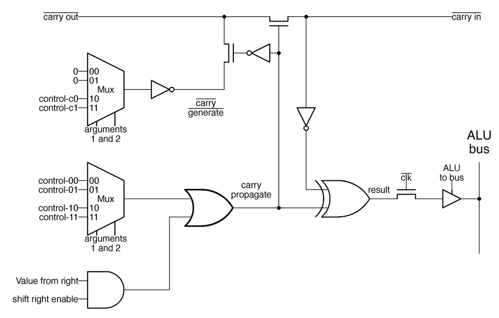
Regarding the multiplexor based ALU of just a few posts ago.
Turns out iNTEL's 8086 leveraged many of the same tricks.
What follows is Ken Shirriff's drawing, not mine.
alu-schematic-w750_downscale.png

Manchester carry chain, MUX with changable inputs, etc.
Seems I can't come up with anything original. Go figure,
surprised as any by what was found under 8086's lid...

http://www.righto.com/2020/08/reverse-engineering-8086s.html
Compare to my drawings from posts #51 and #81.
 
Last edited:
OMG
I love the concept. Gonna read it all, few times at lest!

So far my neurons majority voted I should analyze first posts to get a good feel how it works... because surprise surprise I have no idea 🤯

EDIT://
Actually for few last years I wondered if one could create computers differently using analogue components and if that could be better base than transistors (read: controlled switches) and this looks like answer for my prayers. Kudos for you for bringing this enlightenment to us simple people 🤩
 
Fwiw, the
Code:
[code]
block is what you want. You can specify the language too, if you want, for coloration and to change how tab space is handled. ;)
 
OMG
I love the concept. Gonna read it all, few times at lest!

So far my neurons majority voted I should analyze first posts to get a good feel how it works... because surprise surprise I have no idea 🤯

EDIT://
Actually for few last years I wondered if one could create computers differently using analogue components and if that could be better base than transistors (read: controlled switches) and this looks like answer for my prayers. Kudos for you for bringing this enlightenment to us simple people 🤩
Half my old posts don't make sense even to me who wrote them.
Just move on to the others that do. There have been lots of errors,
not knowing in advance where any of it might lead.

NAND and NOR are universal logics that combine to make any other.
Long known and taught, the proofs are almost self-evident. But these
are not the only universal logics.

Inverters aren't normally universal, but can fake it by abusing power
as a logic input. The same trick also works to give XOR universality.

MINority logic easily makes NAND and NOR, thus proven universal.
4Way MUX makes NAND, NOR, MIN3 MAJ3 and several others.
2Way MUX can combine to make 4Way MUX, universal as well.

But there are important differences between asynchronus logics that
allow for immediate output change whenever the inputs may glitch,
vs synchronus logics that latch a new answer only when clocked.

The most extreme synchronus logics may not even have a fixed
direction of forward flow, but rely on a rolling blackout of any old
latched results to draw new logic results forward into its wake.
Quantum often operates in this category, as do parametrons.

Error: MIN3 can't be wired from a single MUX, not even a 4Way.
Takes at least a pair of MUX working together. Still not difficult...
 
Last edited:
Fwiw, the
Code:
[code]
block is what you want. You can specify the language too, if you want, for coloration and to change how tab space is handled. ;)
Still drops leading spaces, but other column alignments look better.
 
So, quantum parametrons are not oldskool parametrons simply colder...
The quantum digit is a clockwise or counterclockwise flow of DC current.
Not exactly the binary phase shift keyed AC digit of the past. AC is used
to pump a DC bias around the loop. A new concept that at first, second,
or third conventional glance makes no sense whatsoever.

Lets begin by understanding a little about the two Josephson Junctions
that almost but not quite break the loop into two halves. DC supercurrent
can still flow around the loop without resistance. Up to some point where
junctions are tunneling all the supercurrent they can, and begin to resist.

They stop tunneling cooper pairs and begin tunneling unpaired electrons.
Resistance brings current down to where it can tunnel as pairs again.
Then lack of resistance allows current to again saturate the junctions.
And this process repeats. Oscillating resistance creates both an AC
and DC voltage drop across both junctions.

Now you begin to see why it takes two junctions, so each can undo
the voltage drop of the other and complete the loop with no voltage.
But there can be meaningful voltages between one side and the other.

Whats really weird is this process also works in reverse. If we put AC
excitation of appropriate frequency across the junctions, a DC bias will
automagically flow around the loop in response. Without resistance it
quickly builds to the critical limit in one of either possible directions with
no preference. Unless purposely upset by votes from an input circuit,
in which case it will flow with the same direction as the majority vote.

I still don't get how it clocks the DC current and its associated flux to
another loop. Its considered a destructive readout is all I got so far.

I'm also convinced junction size and critcal current must not be so
severely restricted as to supertunnel around a lone quanta of flux.
Needs to drive fanout, and you probably can't fanout from a single.
If transfers of flux can be adiabatic and free of loss, what further
power is saved by downsizing to the point you can't split a result?

There was a drawing to go with, but only made more confusion.
I'll attach later, after I figure a redraw for better sense.
 
Last edited:
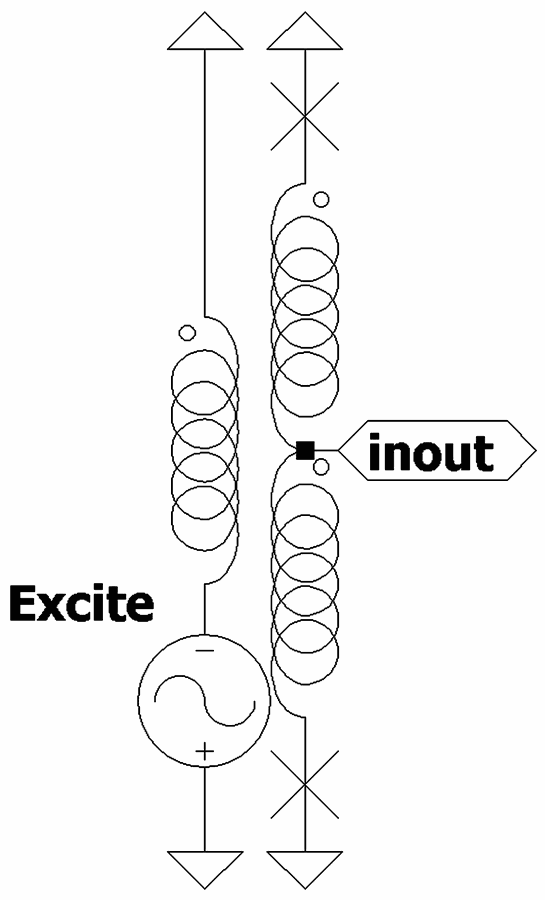
Para1.png


IO is center tapped. So Excite may be coupled to IO, but not in an overt transformer way.
The IO side supports a loop of DC supercurrent (through ground and two Josephsons).
AC excitation mandates spontaneous DC bias appear, but doesn't care which direction.
Probably because no resistance, a fully saturated loop of DC all too easily happens.
How clocking excite can move that DC to other loops, I'm still working to understand.

Hmm, perhaps the lowest energy thing for an idle loop of electrons to do is circulate
to properly bias AC activity already at the junctions? If a slight excess of AC pumping
can excite a slight excess of DC self-bias, there should be a DC voltage drop tween
the IO midpoint and the other side of the loop, which also happens to be ground.
Does positive or negative DC Voltage here reveal the direction of loop current, or
does-not-care? Could Voltage simultaneously encode a separate bit from currrent?
 
Last edited:
1909 World Fair visitors stand in awe of a new Thermos that keeps a beverage
HOT or COLD. Till one asks, "But how do it know?". So maybe thats a clue, or
totally hallucinating again. Nothing hot vs cold here, only cold. But which way
current knows to circulate seems equally mysterious.

Oscillating resistance at a junction requires equal opposite negative resistance
at another to complete the loop at starting voltage. Assume energy for negative
resistance is not free, but provided by parametric pumping.

Incoming or outgoing binary phase shift key'd wave function of supercurrent at
center taps steer a preferred direction as lumpy DC clashes with the timing of
AC excited junctions. Not such an ambiguous or even split as it may appear.
Perhaps one way resists, another way helps, and thats how it know...

As for what makes the bit flow between equal voltages all tied in parallel?
Recall that frequency and only frequency makes a precise DC voltage and
all junctions are pumped at same frequency. Weather thats positive or neg
probably doesn't matter, all in parallel will be same. Except for those on a
sleeping clock pump. Those probably steal current from neighbors to keep
at same voltage. Might be when/how the wave function gets drawn forward.

These are not statements of fact, but grasping straws I don't yet understand.
Believe too much of my nonsense at your own peril.

I still don't know if 2Pi Radians worth of lumpy DC phase current represents
the passage of an electron, a Cooper pair, or an oscillation of the Josephson
that might involve some greater count of electrons. Further reading has me
leaning toward the Cooper Pairs, but not conclusively...
 
Last edited:
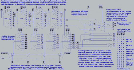
Multiplexer logic again. Simplifying 13 control inputs to a mere twelve. I was hoping a lot fewer, but these may be easier to use. I used to require both CarryFalse and CarryTrue tables for Carry to select between, but the alternate table could also be rendered by simple logic.

-obsolete image thumbnailed-
Decoder.png

If I were to merge my comparator chain's GreaterThan,LessThan with the carry chain's Generate,Kill. Multiplex operations would simultaneously hijack all possible chains and not need ADD to be set any particular way. Maybe I draw that configuration next.

Have also come to realize my Carry True (T0123) table is only used in two special cases: Math, where NXOR is required to oppose XOR. Multiplex where B is required to oppose A. For all other cases, T0123 could be allowed to spew complete nonsense in cases not read. Simpler decoding may be possible.
 
Last edited:
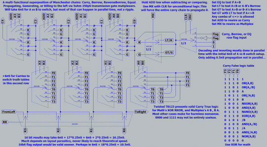
Once we accept nonsense logic for cases that were useless to begin with: Faking the three cases that matter was easy. No logic required. Just shuffle some wires.
Somehow got convenient bonus functions of absolute Set Result and absolute Clear Result. Could already accomplish same, but new options are straightforward.

-obsolete image thumbnailed-
TwistedNXOR.png

Flag overrides CLR and INV are wasting half a dual 4way 3253 and an extra inverter. So maybe I make that an 8way 3251 and feed raw Flag to one of the select lines. Yeah, thats the ticket...
 
Last edited:
Made that useless inverter disappear.

-obsolete image thumbnailed-
8WayInvClr.png

MX still looks messy, but I got no clue how to force all carries to a uniform state faster or with fewer parts. It may just stay like that. Note how ADD's carry chain is the same as Subtract/Compare's borrow chain, except turned inside-out. PKGP is twisted to KPPG. I probably mentioned it before, but its weird enough to mention again. Same chain re-ordering effect as inverting the B select line. Which is why most adders subtract by inverting B, and carry, and the result. All that nonsense for a simple twist of carry's rule that doesn't actually require inversion.

Now I probably did fumble when I merged Borrow's LessThan GreaterThan with Carry's Generate and Kill to make LT/K GT/K. Prolly shoulda named LT/G GT/K instead. Making A minus B the intuitive default. Not that the circuit wouldn't work as drawn. Just bugs me to have misnamed Borrow's new Generate and Kill lines as-if B minus A were the default.

----edit----

Tried that but still looks weird for other reasons. Why did I put A in the middle position? Ohyeah, cause A before B. Need to sleep before I decide if this is a problem.
 
Last edited:
Most deficiencies that were bugging me should be ironed out now.

-obsolete image thumbnailed-
FixedSomeStuff.png

-edit- Ninja swap to fix typos in the drawing and some blurring. Didn't merit a whole new post. Five second rule and all...

-editagain- Whoa, lookidat !?! F0123-->T0123 is the same shuffle as A+B's Carry --> A-B's Borrow. This coincidence suggests an opportunity for future exploitation.

-editagainagain- Not same enough to exploit, even if same. The second row shuffles truth tables just once. But the first row reshuffles Carry at every bit.

Is it Carrys, or Carries? They aren't holes in teeth...
 
Last edited:
A complicated control scheme is just wasting parts and making delay somewhere else. So lets throw parts at a proper decode.

-obsolete image thumbnailed-
FurtherDecode.png

Still feels like MX is too complicated, but I've no grand idea for fixin' it right this second.

For this subset of functions, F0 is always zero, so at least one 4way is doing nothing. No parts saved unless another volunteers to disappear as a pair.
 
Last edited:
MX ADD LT GT now have defined orders of priority to avoid a few nonsense combos. MX CLR INV could use more work in that same department.

Dropped a pair of 4ways by aligning coincidences. Any choice of four zeros (dotted vertical rectangles) would be zero, and needs no parts.

The first coincidence in the Carry True tables was a gimme. Didn't plan it, but obvious that F0 could be dumbed down to a simple 0.

Exchanged NAND for the 0 function to make an exploitable second coincidence in the Carry False tables.

/A was another option that could have made the second coincidence.


WhyIsSimpleSoDamnComplex.png


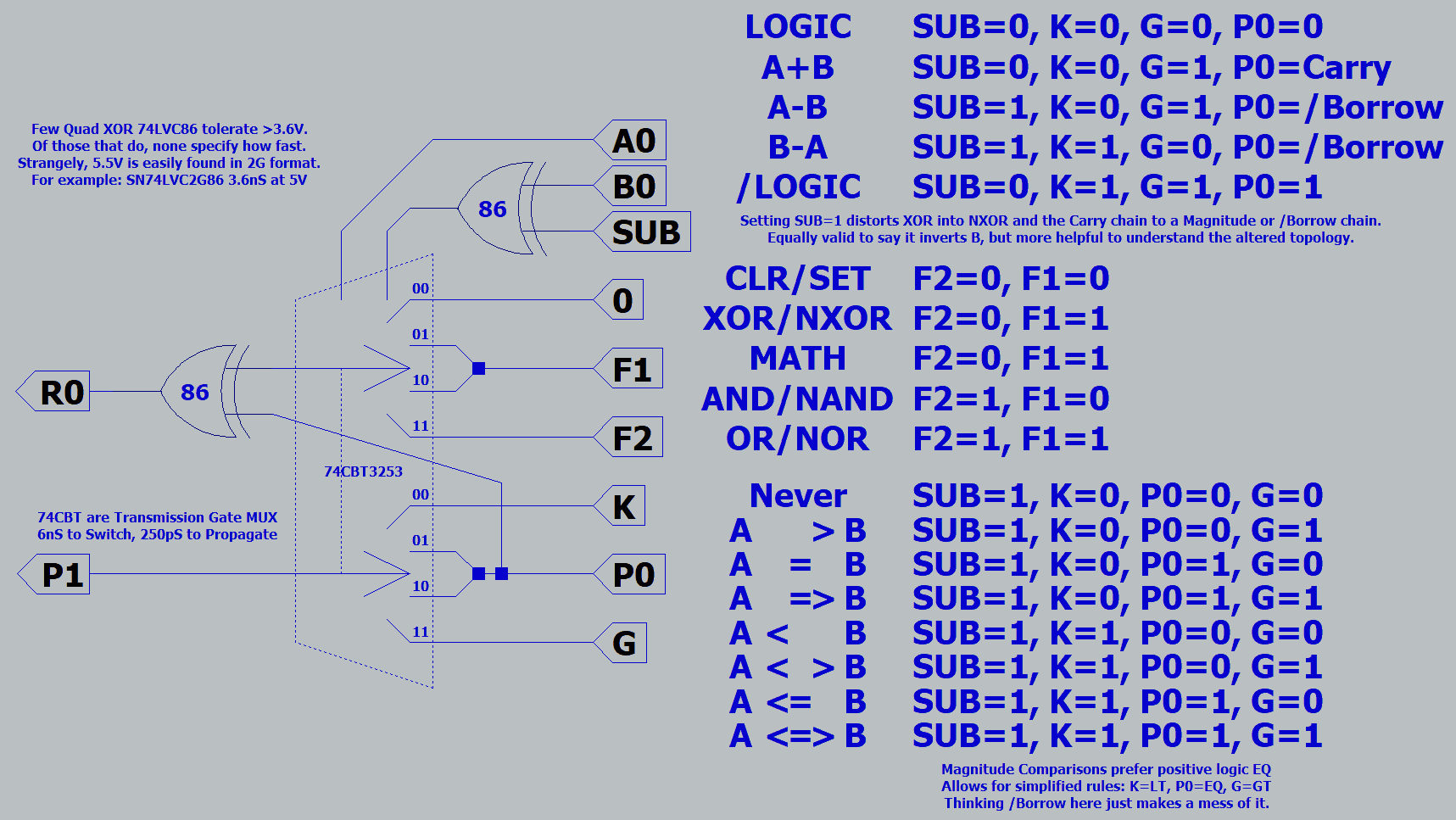
Down to nine control lines from somewhere off-drawing. Better than twelve, but still too many. S0,S1,MX,ADD,LT,GT,CLR,INV,RR yep nine. FLAG's mixed duty has been split and the functional part diverted to INVorEQorS2. Raw FLAG now can connect straight to data without control expectations. The crazy mix of INVorEQorS2 might be a good thing. As all are 100% function not mixed with data, all can map to one instruction bit.
 
Last edited:
ALU_Breadboard1.jpg

Needs power, ground, decoder. Lights and switches not a priority. May skip decoding and let an arduino begin checking wether direct control even works.
LSB is on the right. SUB was wired as the alternate chain, rather than ADD. Otherwise mostly per last posted drawing.
Hope to piggybug at least 4bits per adapter to cut down on spaghetti, then maybe lights...
 
Last edited:
Lets talk decoding for a moment. How to reduce the number of control lines required?

4way multiplex allows lookup of 16 possible truths. Each representing a two input - one output logic function.
Now I propose we separate two basic groups of those functions: The useful group and the weirdo group...

Usefuls might be: CLEAR 0000, NOR 0001, XOR 0110, NAND 0111, AND 1000, NXOR 1001, OR 1110, SET 1111.
Easily squished to: CLEAR 000, NOR 001, XOR 010, NAND 011, AND 100, NXOR 101, OR 110, SET 111.
Each obeys "middle pair are same". Meaning this group doesn't give a damn which input is A, which is B.
A control line can obviously be saved here with no parts and no work.

Weird truths treat A vs B differently, representing strange asymmetrical functions such as AND(A,NOT(B)).
These truths won't easily compress, but we also might not cry if they disappear. Not to say that weirdo
functions have no use case. A 1100, B 1010 obviously cares which input is A vs B. This pair are needed
for MUX(A,B) when selected by Carry. NOT(A) NOT(B) similarly care; I don't care and choose to ignore.

Six truths do not immediately suggest practical use when traditionally listed as mere boolean functions.
Yet I can put all to good use simply by suggesting better names. Let AND(A,NOT(B)) be known as A>B.
Every one represents magnitude comparison. The magnitude comparator and borrow chain use them all!
Problem with these functions has always been our thought process corrupted by old 74181's spec sheet.

Magnitude comparison < = > functions overlap with A, B, NOT(A), NOT(B). Don't let the duality distract.
Edit: Total BS just above, A B ignore one input and are not magnitude comparisons. Actual overlaps are:
Code:
000 NEVER , CLR
001 A  >B , AND (A,/B)
010 A = B , NXOR
011 A =>B , OR  (A,/B)
100 A<  B , AND (/A,B)
101 A< >B , XOR
110 A<= B , OR  (/A,B)
111 A<=>B , SET
Borrow chain functions are selected per LT, EQ, GT control lines. EQ also happens to be the main Carry.
Don't let THAT duality confuse. More meaningful to think of Magnitude logic here than equivalent stand-
alone Boolean logics.

With that said, borrow chain functions can and should be decoded separately from Boolean functions.
Programs will have definate use for the weirdo group as chain functions. Bitwise, not so much if ever.
No need for Magnitude decode to fully represent all Boolean functions. No need for Boolean decoder
to fully represent all Magnitude functions. Except A vs B Weirdo function might be worth some trouble.
We'll get back to that exception later.

Now lets talk about the naughty functions. You know, the ones that start with a zero or naught bit.
CLEAR 000, NOR 001, XOR 010, NAND 011. Assign to be available only when Carry is false.
AND 100, NXOR 101, OR 110, SET 111. Assign to be available only when Carry is true.
Thus the four control lines associated with Carry True are fed, simply by splitting the table.
Also eliminating a control associated with the highlighted bit, since Carry now provides.
Do need to be careful how much fanout Carry is asked to drive when we cheat like this.

Math operations A+B, A-B, B-A all want XOR logic. Unless there's a Carry, then use NXOR instead.
But inconveniently for math: We find XOR to be opposite OR, NOR opposite NXOR. This won't do.
Inverting the last pair of alternative truth wires can fix that. Now CLR opposes SET, NOR opposes
OR, XOR opposes NXOR (exactly as we need for math), NAND opposes AND. All nice and regular.

We could save two gates by swapping those wires instead of inverting them. Though it leaves SET
CLEAR in funny locations not opposite each other, it does conveniently leave NAND opposite SET.
My opinion: These are the least needed pair, soon to be sacrificed on the unholy altar of MUX(A,B).

Boolean decode summary:
Carry False Functions
000 0000 CLR
001 0001 NOR
010 0110 XOR
011 1100 A
Carry True Functions
100 1000 AND
101 1110 OR
110 1001 NXOR
111 1010 B

Two controls, a twisted pair, and a carry seem much lighter weight than eight control lines.
Not saying this plan won't suffer further needless revision ad nauseam. Still needing detail
exactly how A B might ninja swap in place of properly decoded NAND SET. May have just
painted myself into another corner...
 
Last edited:
Ditching ALU MUX(A,B) capability, which there are several other ways to implement.
This allows a greatly simplified control scheme. A single Manchester Carry chain is
bent (by inverting B) to handle subtraction and magnitude. Chain wiring can happen
all on one physical side of the SOIC package, which should facilitate vertical stackup.

One of the truth table inputs, F0, represens a constant 0 or ground. Best orients to
the side with convenient access to the GND pin. Leaving the chain to VCC's side.

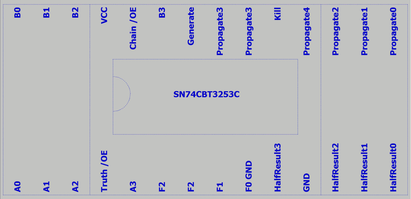
Stacked onto an oversized 28pin SOIC to DIP28 converter, gives a 16 pin SOIC
12 extra IO pins? 5bits should be stackable. Only shooting for a dogpile of four.

No, wait. Gotta breakout an extra A,B,P,R per each stacked bit. Four, perfect!
XOR aren't in the critical path and should not clutter the stack, but do require
intermediate carry bits be exposed for that purpose. Thus the extra pincount.
Final A,B,P,R of the stack is a given, covered by original 16pins of the device.

TransmissionGateALU.png


After breadboarding, I was alarmed by all the spaghetti my earlier plan required.
Also concerned 8way would have to do a Uturn round one end. Chaining 2 pins
from one side of the SOIC with three from the other. Can't easily cross under or
over an IC embedded in the middle of a piggybug stack. With dual 4way pinouts,
that seems unlikely to be a problem, and maybe half the parasitic capacitance.

Two XOR gates offer very similar delay to a single CBT mux. 2.7V 74AUC2G86
might even be slightly faster. If the logic levels will cooperate, and specs suggest
they should be OK. I have some 74S86 in nearby storage I could use temporarily.
Though a pair of S86 gates is definately slower, my goal is to measure the delay
of carry, borrow, equal, or unequal. Unaffected by speed of XOR.

The new plan needs no decoder, except to clear and/or invert main Carry input.
Not sure this function alone constitutes "decoding". Back when it was mixed
with funky setups for MX and ADD, that version definately qualified as decode.
 
Last edited:
I don't have anything to add, I do want to say that this is fantastic work. This kind of innovation leads to breakthroughs and it's exciting to see it happening in this field at a grassroots level.

I know you've been at it a while, please keep going.
 
Might pile them up in stacks of four, something like this...
Least significant bit on top, Most significant on bottom.

PiggybugBreakout.png


Each pile would need a supporting pair of 74S86 quad XOR.
Maybe later, a faster quartet of 74LVC2G86 or 74AUC2G86.
 
Last edited:
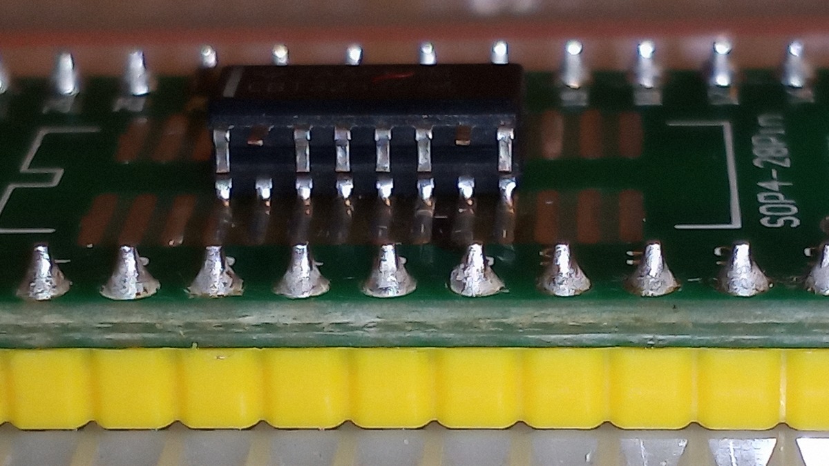
Well, that sux. Even folded down to look like DIP, SOIC pins
aren't long enough to touch the next chip underneath. What
do I do to fix this? Sand bottoms and tops before bending?
Or I gotta lay an actual wire down each connected column?

SOIC_piggybug_won't_reach.jpg


Or I could put each on an adaptor board before stacking,
though that wouldn't give the shortest possible distance.
 
Last edited:
Well, that sux. Even folded down to look like DIP, SOIC pins
aren't long enough to touch the next chip underneath. What
do I do to fix this? Sand bottoms and tops before bending?
Or I gotta lay an actual wire down each connected column?
I would join them with a wire.
 
Just tried that. Wired columns are a disaster.
Way too fiddly trying to hold it all straight.
Even abusing the breadboard to hold the
other end stationary.

Need a stereo microscope and extra hands.

Maybe if I superglued the chips together
instead of relying entirely on tacky flux that
runs liquid every time I heat a pin. Once IC's
stop moving, I can better focus on the wire.

If I could fix at least two columns perfectly
even if it looks like a blob. That might allow
the rest to go smoothly, then cleanup later.
 
Last edited:
Could you take a properly sized pin header. Flip it upside down and run the pins down to the board solder the chip pins to the header? That would keep the "wires" in place and spaced where they need to be.

Also why not prototype on a fpga? Is this to a point where you need to see how it does on gateless chips?
 
Fan the pins out horizontally and solder them to a small pcb with a 90-degree header on the back side, and solder or socket the header into the main board below? More work and more expensive, but for a one-off it'd work.
 
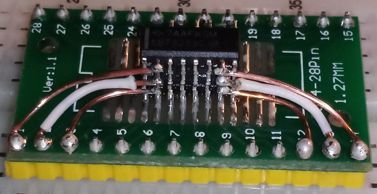
Truth table side done and partially cleaned.

TableSide.jpg


These aren't gateless. I havn't forgot about gateless, just not what this is.
FPGA do not offer transmission gates required for an instant pass-through
carry chain. Header pins are way too thick for SOIC spacing, already tried.

I have plenty of adaptor PCBs to fan out pins if I choose to stack adaptors.
But wiring carry short as possible (not yet started on the other side) was
and is my ultimate lame excuse for trying the [H]ard way first. That said,
I should have and haven't yet cut away several unused traces. Whole
backside is unused layout for TSSOP. Maybe obsess those details later.
Connected but unused traces definately count as parasitic sphaghetti.

I did glue the chips together as a tight straight stack before soldering.
One drop of waterthin Starbond on the end. Capillary action took care
of the rest without gunking up any pins. Pins were then bent close to
the body (which you are never supposed to do) to make reach.
 
Last edited:
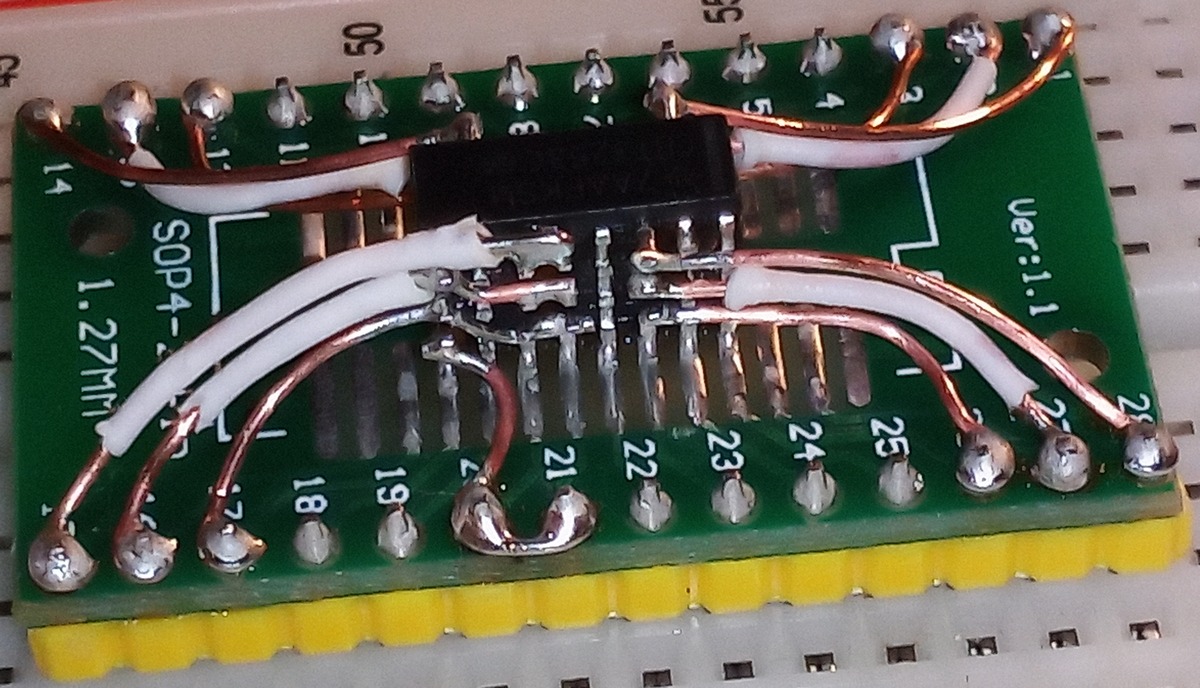
Carry chain done. Flow is from top to bottom.

ChainSide.jpg


Those beefy wires are scavenged from CAT5. Dunno what happened
to my roll of blue Kynar, probably find it after I'm done. Kynar doesn't
melt quite so easy or shrink back from where it was cut.

This was an absolute mess, too tiny to get right without a microscope.
Having done it the [H]ard way once just because, I'm more inclined to
build the rest on stacked adaptors. Wasted enough hours and parts...
 
Last edited:
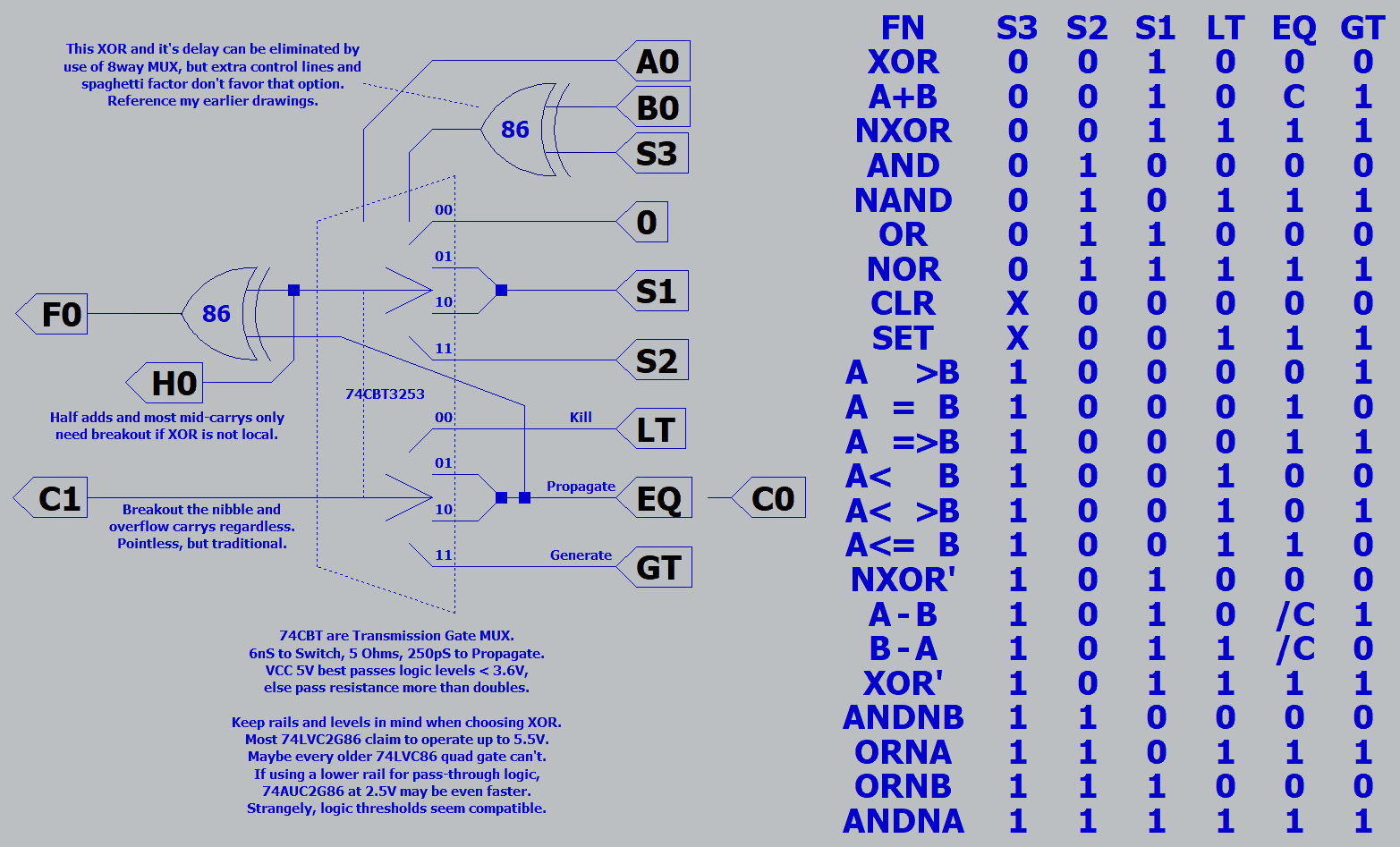
Completely unchanged circuit, only better documented.

XOR_MUX_XOR.png


74AUC2G86 spec at 2nS per gate. A pair should be faster than 6nS 74CBT3251 they replaced.

XOR XNOR are used by addition. Redundant NXOR' XOR' fix subtraction's inverted borrow.
Same exact functions, slightly different control scheme. Only magic' by listing in reverse order.
Not talking here about either of the real 86 gates, but half adder logic defined by S1 S2 etc...

Let the Carry /Borrow Equal chain begin with an 8way 74CBT3251. Selecting a lookup table of
eight fresh power or ground rail constants. Representing all cases of raw Carry flag as cleared,
set, passed, or inverted. The selection can be made and passed in 6.25nS. Not needed to feed
our first slice's EQ input till 8nS, not contributing delay. Review #104 for example of that input.
Upper rightmost multiplexer of the drawing, yeah that sneaky one crouched behind the post-it...
 
Last edited:
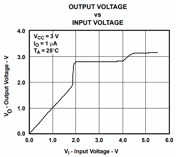
Also reading about a strange MUX family that strengthens pass-logic by pulling up signals
that are already over half. I dunno if thats a good idea or not, what keeps it from latching?
One of these every byte or so might allow for a very long carry chain, but might also dumb
things down to a simple ripple, which I don't want.

WhichEndIsWhich.png

https://www.ti.com/lit/ds/symlink/sn74cb3t3253.pdf

OK, but this is a pass-though logic device. Which end is input? Which end is output?
Can't have gain both ways, or its gonna latch for sure.

How do you claim 5-7ohms across nearly a Volt of boost? Ohms law sais 142mA!
This too makes no sense, unless there is disconnect when there is boost. But the
question reverts to which end is input? And if there is a disconnect, is that another
6nS to switch?

Here they say bidirectional voltage translation requires both sides be open drain.
I dunno if that applies to this part. If-so, that doesn't sound useful to my purpose.
https://www.ti.com/logic-circuit/voltage-level-translation/overview.html

This other part maybe explains better. For me, this also confirms a dead end.
https://www.ti.com/lit/ds/symlink/lsf0204.pdf

A pullup resistor (internal or external?) must exist on either side of a switch.
Logics on either side are only allowed to pull down, open collector or drain.
All the switch need do is block when either voltage rises above threshold
and let resistors pull each to a different VCC.

If either logic pulls down, and if that gate is also enabled and selected, the
gate conducts and both sides pull down together.

Not every absurd distraction leads somewhere...
 
Last edited:
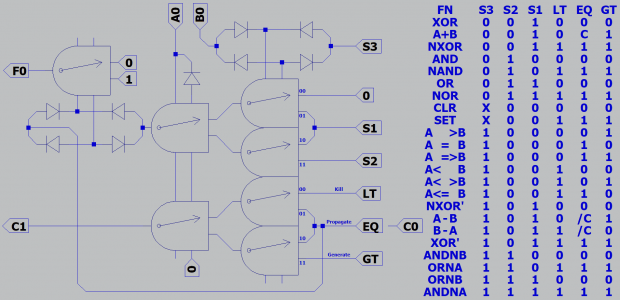
In you wonder how MUX logic evolves from relay logic:

SameWithRelay.png

Keep in mind that Voltage difference across a coil performs XOR.
Diode bridges aren't XOR, but to keep coils from throwing sparks.

Though seems a waste to use only SPDT as the final full adder.
Was more important to show same as possible the MUX circuit.

Easy upgrade to DPDT and pass-through test for zero in parallel.
Yes, redundant to the magnitude chain, but free and immediate.
My usual peeve about a zero test is added delay, but none here.

Interesting. Four DPDT are one less than my previous hot melt
glue on popsicle stick contraption that lacked the diode bridges
needed to make it reliable. Only three relays if one's a QPDT...

4RelayWZero.png
 
Last edited:
I found my old stash of 74S86 XORs. 5v, power hungry, faster than average,
already DIP, won't need any adaptors. Fine for testing wether the plan gives
correct math results. Speed of carry chain measurement won't be affected.

3relay will definately replace 5relay for the demo box with vintage lamps.
Most likely using fake Omron 4P2T's as best presentable. Extra poles may
facilitate wiring 110VAC for lamps.

I have 18V MOVs on the coils of my 4P2T's now. With -20V flyback (if driving
logic can handle that), may release quicker than diode bridges freewheeling
with a mere -1.4V drop.

Elliot sais quick release may be needed for breaking welds at point of contact.
He used 270 ohm in series w a diode. https://sound-au.com/articles/relays.htm

Welds do happen. I can attest whilst banging an older ALU on workbench
to unstick...
 
Last edited:
Back
Top