Gateless Majority Logic

While composing a difficult email to Japan, fishing long lost secrets of Takahasi's non-quantum DGate:
I was drawing lame pictures again to make up for my complete illiteracy in both Japango and Engrish.
But none of that is my current point, only the story of how I've gone from confused to completely nuts...

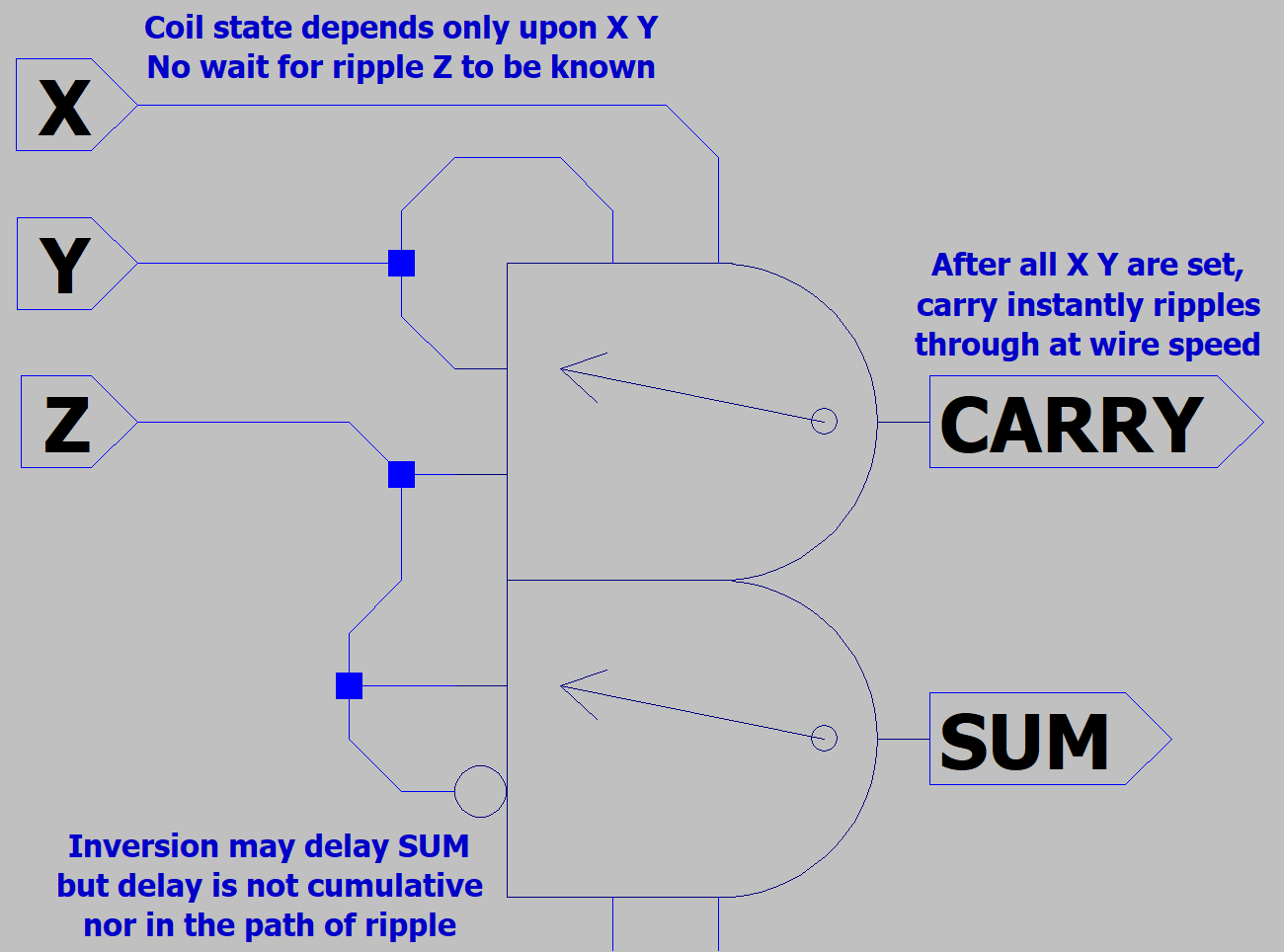
I stumbled upon something that only relays (and maybe mosfets) can do. Instant Pass Through Carry.
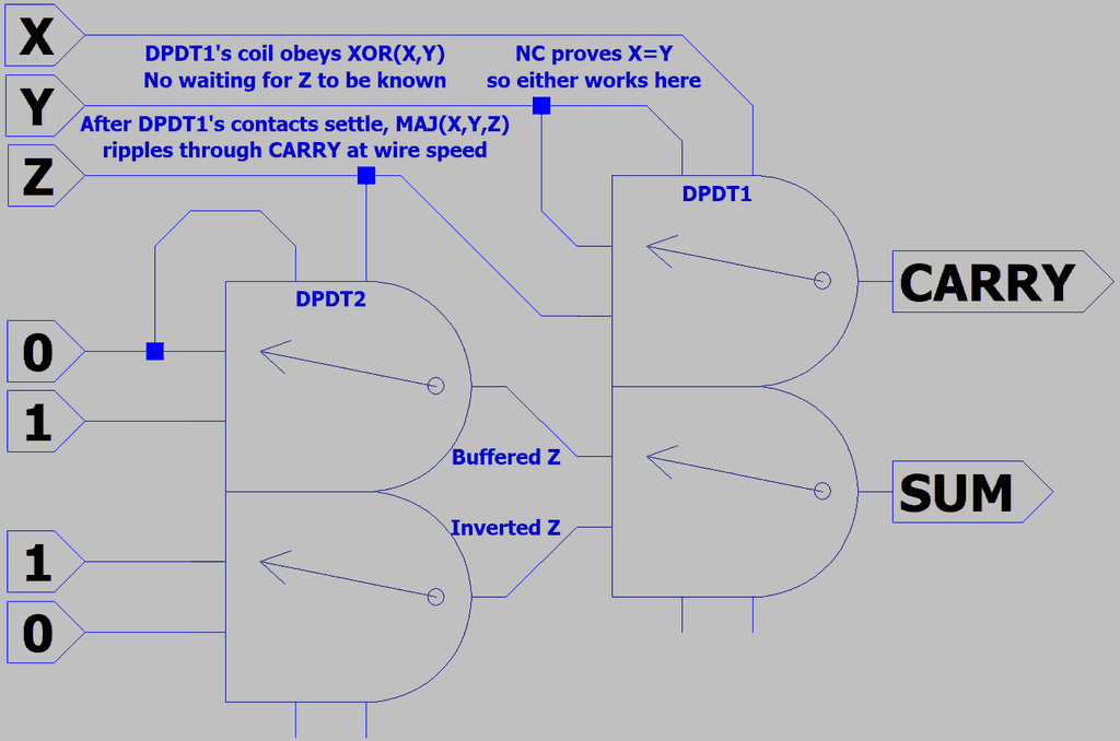
Check it out: The coil performs XOR, and nothing thereafter needs to move for Carry to ripple through.

Once all carries are known. Wait one invert of delay, and all sums can also be known. The number of
bits doesn't matter. Carry look-ahead in this case would be pointless, ripple may be as quick or better.
RelayAdder.png


If you are hurried for SUMs and don't want to wait one extra cycle on relay inversion.
You could use inverting transformers instead. No moving parts, and the speed of wire.

Transformers can't invert DC. If you chose to use transformers, would have to rely on
opposing AC phases. Two signals of similar phase won't activate, but opposites would.
Wether AC or DC driven, a relay's coil is activated by the same logic function as XOR.

Doesn't matter which end of a XOR coil might also feed the normally closed contact.
Normally closed proves both coil inputs to be in the same AC or DC state anyhow.
If X Y are the same, they also rule the Majority. If X Y differed, the switch would be
pointing at Z instead, for a tie breaker. Carry shares the same logic as Majority Vote.
 
Last edited:
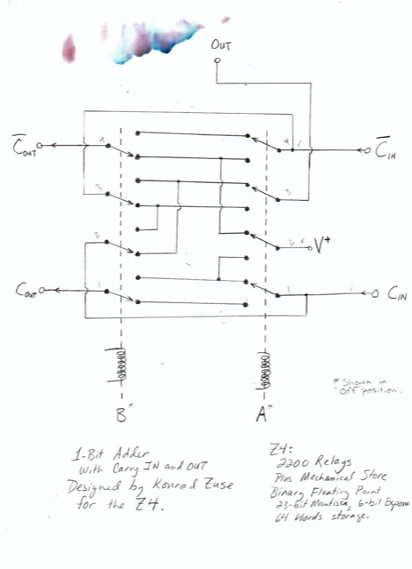
I've been informed by Harry Porter that I've independently reinvented
Konrad Zuse's Full Adder. It had a similar instant ripple, but omits the
inverter. Instead using the "Swap with Evil Twin" method of inversion.
Revisit post #13 if that theory is no longer fresh in mind.

Zuse'sAdder.png


Sixteen contact points seems a bit much though. Assuming a relay
could serve for both inversion and reinforcement, I've used only eight
contacts and the same count of coils.

In my scheme, one step of inverter delay exists between instant ripple
and sums. Konrad's assumed inverter to setup the evil twin carry input
must be somewhere off-page. One step of delay before instant ripple.

Both schemes have fanout issues. Comparing worst cases: My carry
may have to drive N DPDT's configred as buffers/inverters. Konrad's
notcarry may have to drive N sums. If each sum drives a fan of one,
its a wash. If each sum has to drive a larger fanout, then my scheme
guarantees fresh drive per sum.

If transformers act as inverters, sums require one less mechanical step.
But driving N transformers plus N or more sum loads strains carry fanout.
Doubtful that AC (required for transformers) could drive coils faster than
DC. Dead time around zero crossings can't be helping. Reactance and
audible noise become problems if drive current alternates too quicky.

My idea to abuse AC phase logic to save moving parts in a relay adder
might have been shortsighted and wearing the wrong goggles. Every
problem now has to be solved by Parametons. Like Pythagorus with
his damn triangles. Or a sasquach who just re-discovered the wheel.

Apparently Zuse is pronounced Tsusza, and Harry Porter ain't Potter.
Other sources maintain this adder was first used in Konrad's Z3.
I just want the story behind that smudge.

http://web.cecs.pdx.edu/~harry/Relay/
 
Last edited:
Evolved to improve fanout. Worst prior case, one contact could have been asked to drive every sum's loads.
The non-inverting case deserved buffering as well. Yes, that added two contact points. Now a pair of DPDT.

TwinDPDT.png


Still only half as many contact points as Konrad's. Perhaps his sixteen contact adder could do other nifty things?

Recall post #37, where several nifty things SPDT, DPDT, and DGates could do were detailed. DGate isn't quite
the same animal. Cause oscillators must ring up and latch a phase, instant ripple for DGate doesn't seem likely.
In DGate's favor: you get amplification at every relay-like gate, synchronus pipeline, and free optional inversion.
How logics that share the same simple truth table could be so different...

Aside from adding with a negated number, I can't yet imagine an instant ripple circuit for borrow. Maybe later...
 
Last edited:
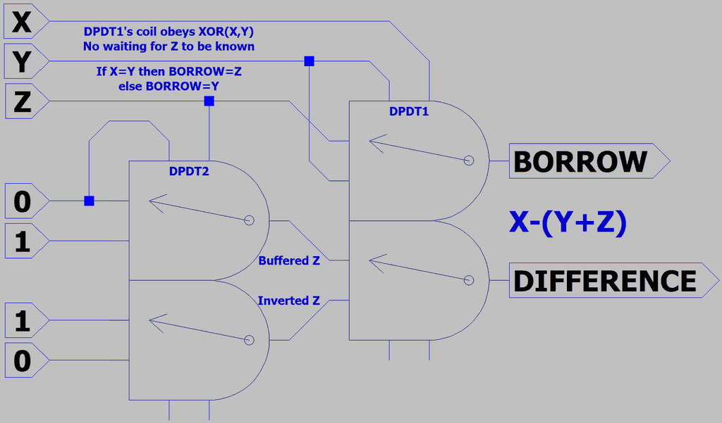
Subtraction with instant ripple wasn't impossible after all.
Had to abandon my circuit from Post #37 and start over.

TwinDPDT Subtract.png


Post #43 proved a better starting point. Swap NC for NO
for the top half of DPDT1 only. Not sure how complex it
is from here to make an ALU that does several things?

You might already have noticed SUM=DIFFERENCE.
Only challenge was that CARRY differs from BORROW.
For subtraction, X holds a different sign than Y and Z.

Perhaps we can aproximate the same circuit quantum
style, with reversible Feynman gates? But driving a
large fanout might make true reversibility impractical.
If I replace a signal with a freshly amplified copy, does
that count as killing off the original? I think it does...

Another DPDT to configure function could easily swap
two lines, simultaneous with XOR(X,Y) coils setting up.
So as not to waste any extra time. But what of other
functions? Not worried about AND OR. Worried about
shift right, since it must ripple in the opposite direction.

In my MRAM cheatsheet lookup table ALU (not of this
thread), I had a function that could mirror flip bit order.
01234567=76543210. Allows a leftward unidirectional
ripple (X+X equals X shifted 1 bit left) solve problems
that need rotate or shift to the right. I'm sure relays can
perform the same trick.

As with swapping NO for NC when subtracting, pass-
through substitution jitsu shouldn't eat any extra cycle.
One clack at the most, probably none. We know early,
from the instruction, what function rewiring is needed.
 
Last edited:
NASA wants to crowdsource ideas for a clockwork Venus rover with no electronics.
Seems to be a broken assumption that reliable digital electronics ends at 120C.

Those fools just need parametrons and an alternator to spin up three clock groups
of AC exciting currents. Gas filled thyratrons might serve as diodes. And relaxation
oscillators, if you rather excite with those. Reduce parametron DC bias requirement
with some alnico permanant bias.

https://en.wikipedia.org/wiki/Thyratron
https://en.wikipedia.org/wiki/Alnico

Why I have to sign up for spam to submit an idea? Let them figure themselves.
Contest prize is for a mechanics sensor. Nothing for suggesting the whole idea
of abandoning electronics is dumb.

Others have already pointed out relays. Wetted reed relays might be reliable.
Not saying mercury, but whatever melts on Venus, low temp solder perhaps?

Review Post #15 of this thread. Parametric amplifiers can be used for radio.
Vacuum tube technology might also be worth revisiting for radio purposes.
 
Last edited:
Did you know that DC had a phase? I didn't. "Phase current", go figure...

While reading Josephson Junctions, the lighbulb in my head just started a dim glow.
Some equations that confused weren't always talking AC, but sometimes DC phase.
Like counting individual cars as waves on the road rather than a steady rate of flow.

All current paths in a superconductor are required to wave integer full circles of 360
degrees (or 2pi radians) before DC can loop the same path again. Because there
are many paths to simultaneously solve, that locks a whole brick into one uniform
state regardless of its size. Maybe also what a condensate means? I'm not sure.

Lets shape that brick into a loop. At some point on the loop we paint a finish line.
With a hot chick waving a checkered flag, or maybe its just a Josephson tunnel
Junction. She's flagging each car in the Cooper pair HOV lane as-if a wave had
passed, but we know its cars... And each car is a 2pi phase shift in the wave
function of the race. More phase shift, more cars pass per lap, more DC PHASE
CURRENT. For quantum purposes, more conveniently expressed in Radians
than Amps...

And count of flux lines in the loop are the same integer count as waves of phase
current going around the loop. Least thats my current state of misunderstanding...
 
Last edited:
Still noodling on relays. Not serious to build anything of them.
So many ways to stretch the functions of this primitive device.
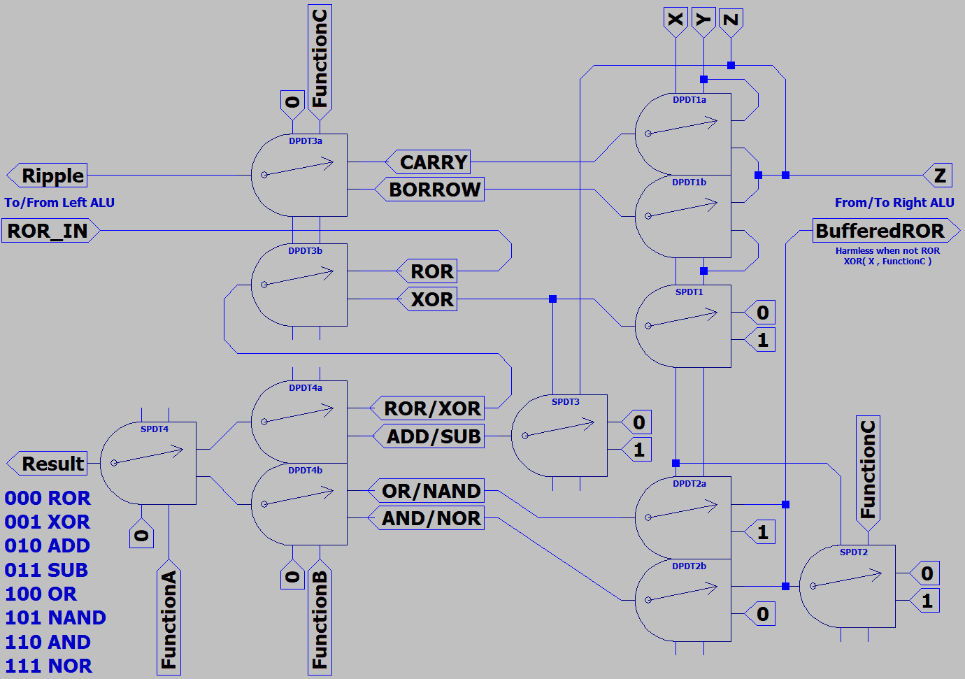
Instant Ripple, Coil XOR, Majority Logic, Multiplexing.

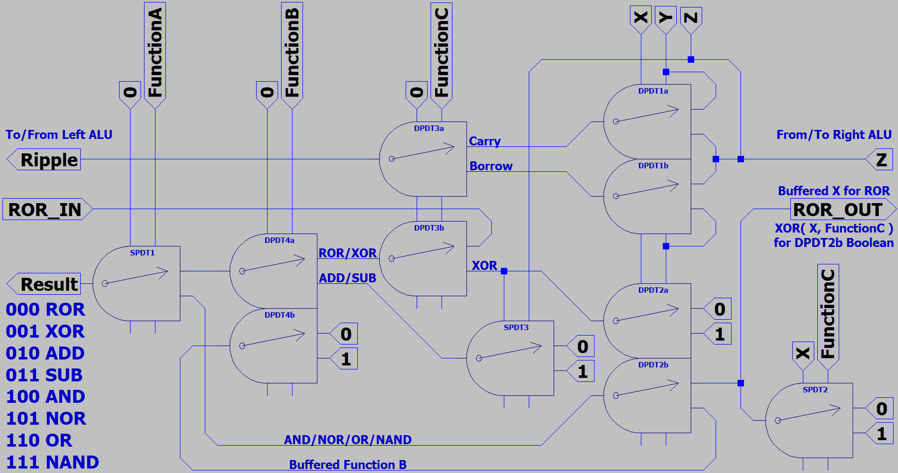
8RelayALU1.png


Hopefully I remembered to buffer all possible results.
Each re-driven by fresh local constants at some point.

Only lightly loaded instant ripple should omit buffers.
No more than one coil load on ripple per ALU slice.
Here, SPDT3 was a necessary load for arithmetic.
Not in direct path of ripple.

7RelayALU2.png


Now much harder to explain the way AND/NOR/OR/NAND were derived, but managed to rid a relay..

-edit- occoured to me much later that SPDT1 just before the result could be shared between bit slices.
ALU slices are driven by the same function lines. Replace SPDT1 w 4PDT, needs 1/4 relay per slice.

FunctionB DPDT could also upgrade to 4PDT and share between slices. 1/2 relay used per slice.
Mentioned before, DPDT1 and DPDT2 could also gang together as 4PDT to save another relay.

All savings bring the relay count down to 4.25 relay per bit, assuming 4PDT aren't priced stOOpid.
Saw Qty10 for $15 free ship on aliexpress before it started demanding my login to browse further.
Not to buy or donkeycart, login is now required just to search. Maybe they are under denial attack
or something? Those also seem to have an LED in parallel with coil, but only works one direction.
Wonder if LEDs could be upgraded to Red/Green type that light a different color per direction?

Domestic resellers of Chinese of DPDT ask around $1.20 each. Might require 6.5 DPDT per bit.
SPDT are right at a dollar, perhaps not worth mixing in. Domestic 4PDT $7.50ea, forget those.

Yeah, 4.25 relays per slice, after linking four slices and exploiting share. Qty9 4P2T + Qty8 1P2T.
Nothing new in this picture (I did draw it out), except too wide to fit screen. Pointless to upload...

Relay I'm looking at now is Omron MY4NJ, and socket PYF14A that snaps on a DIN rail.
Together $1.89, not including the rail. https://www.aliexpress.com/item/32859061939.html
Another code to search for same relay HH54P.

Bare relay, without socket, 90 cents. https://www.aliexpress.com/item/33026209849.html
Nevermind 90 cents. Soon as you + + + up to Qty4, shipping jumps from free to $3.37

30cent PCB DPDT's with no extras. https://www.aliexpress.com/item/32698886122.html
Maybe hot melt glue them to a 2x4 dead bug style? Found some like this already in the
trash. Some had to bang on the table to unstick, you know the drill. There's a popsicle
stick here about the right size to line up seven. Where's my damn glue gun gone to???
 
Last edited:
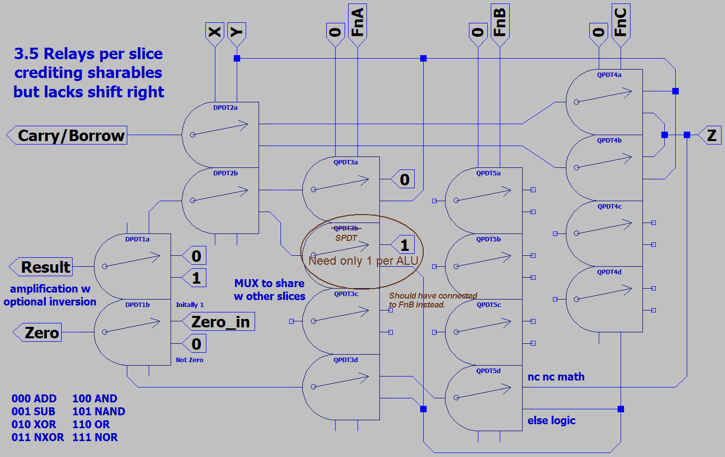
Now down to 3.5 relays per bitslice when optimized for sharing.
Across a byte, all those floating poles eventually do get used.
Just noticed, QPDT3b is driven by shared functions and constants only.
If one SPDT per byte might do there. Two QPDT per byte could be saved.
3.375 relays per slice. Marked that up and noted a function routing error.
Something weird must have happened in the desphaghettification ritual.
3'375RelayALUwZero.png

Managed to throw in Zero detection at no extra cost, and gained NXOR.
But streamlined out a very important ROR function, which begs some replacement.
Can patch this weakness with lookup table in memory, or 8 way MUX +2.25 relays per slice.
You might count an 8 way MUX as only +2 relays (w QPDT sharing), +.25 for amplification.
Thinking: Circle L R 1 or 2 places, Nibswap, Reversal<>lasreveR, RRwCarry, SRArithmetic
A nice round 16 functions...

Wonder what any of this relay gated nonsense might still have to do with the original topic?
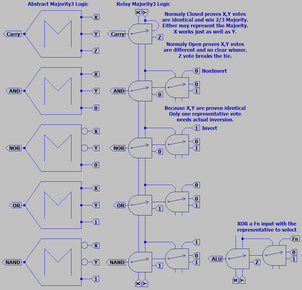
Let us consider how the Boolean functions are derived...
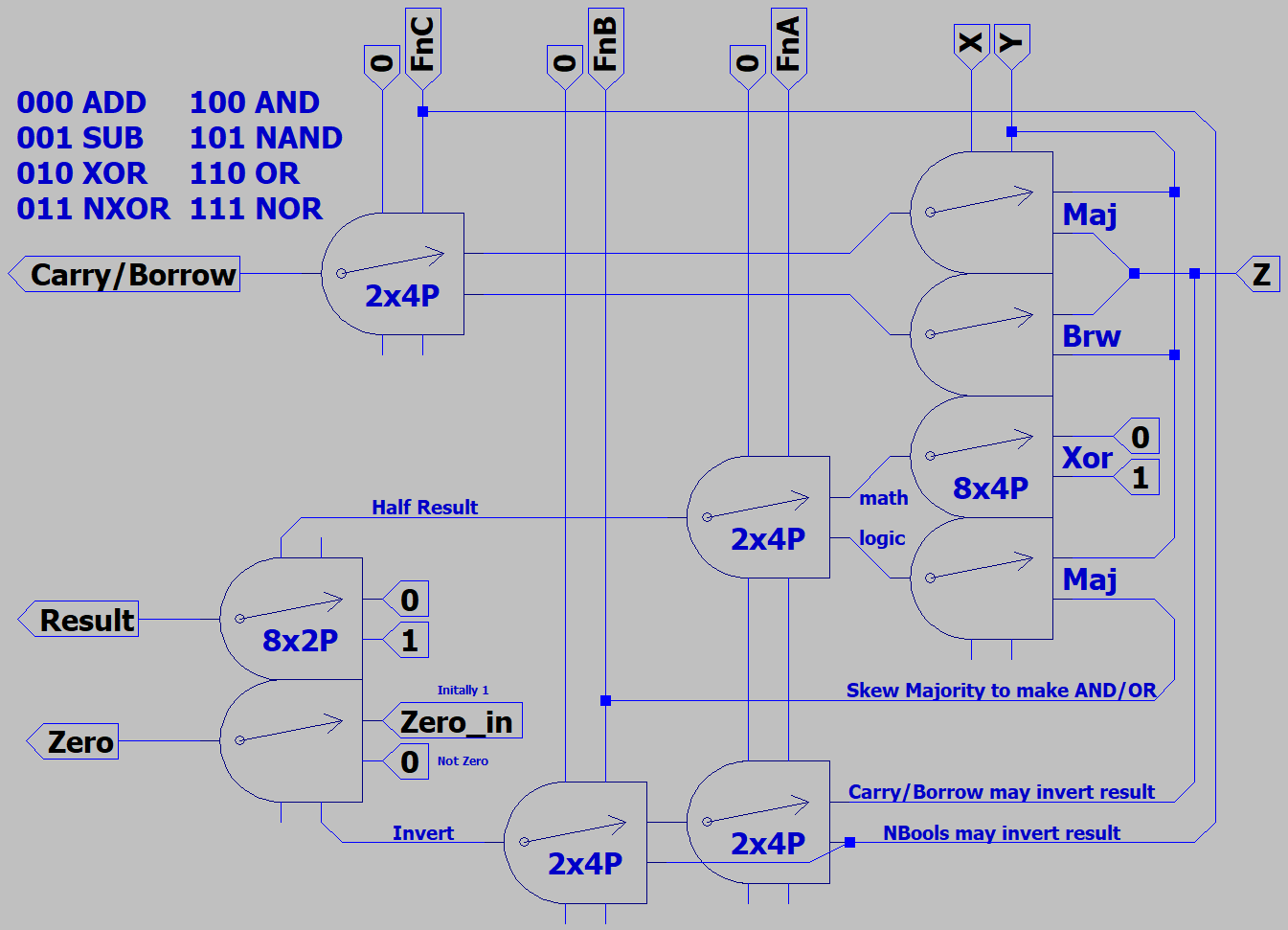
RelayMajority3.png

Keep in mind that inverting the output is the same as inverting all three inputs.
 
Last edited:
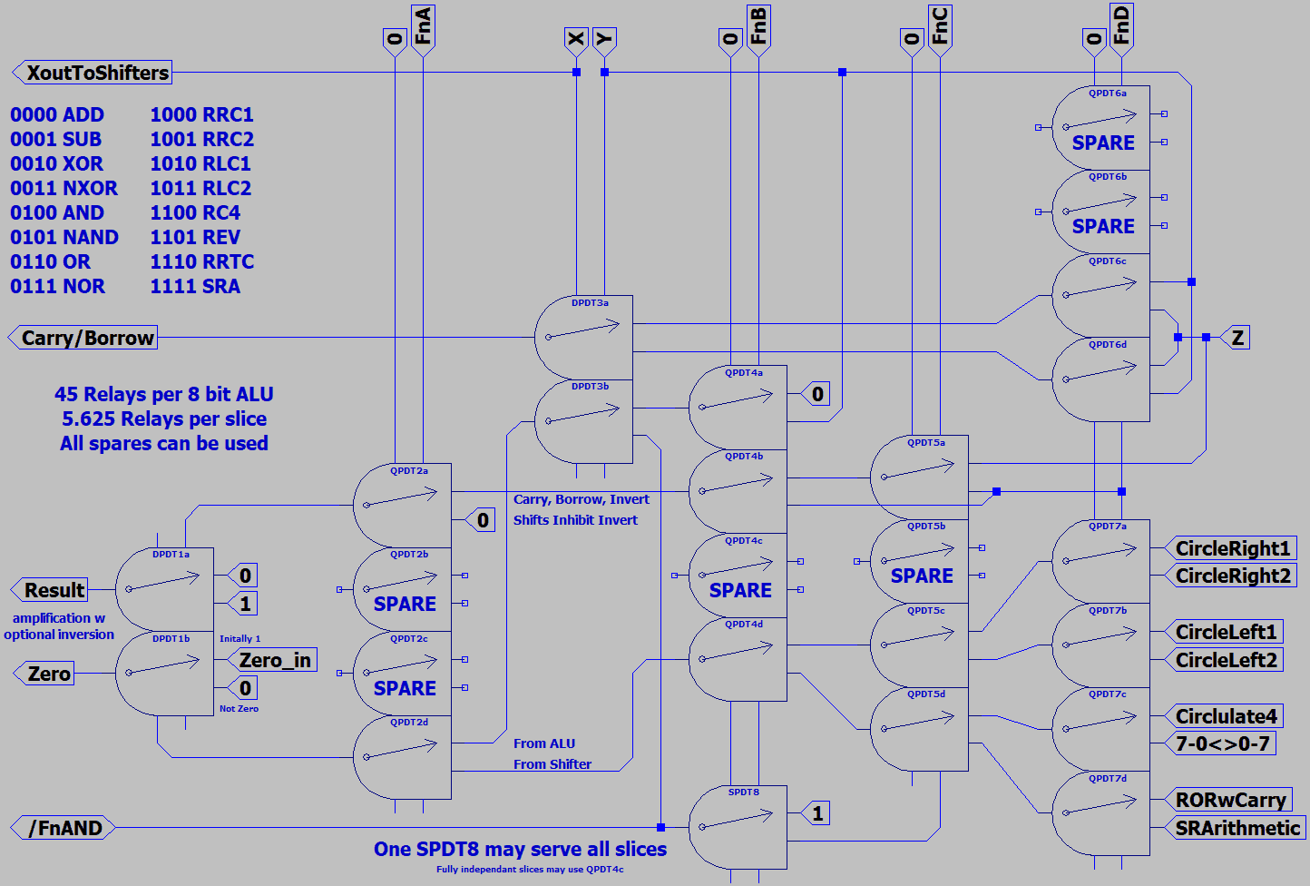
Hopefully no mistakes this time...
16FnALU.png

Zero flag is 1 when True and all results are Zero. Thats the way its normally done, right?
Prolly cause a Zero flag thats Zero when Zero made too much sense.
https://en.wikipedia.org/wiki/Zero_flag

The shifters are a small pyramid of mux that might connect any eight arbitrary inputs.
Choose your favorite Shifts, Constants, Registers, Front Panel Switches, whatever...
64 arbitrary input bits, if you think of the whole ALU bytewide.
I could still map arbitrary shift patterns to MRAM instead.
 
Last edited:
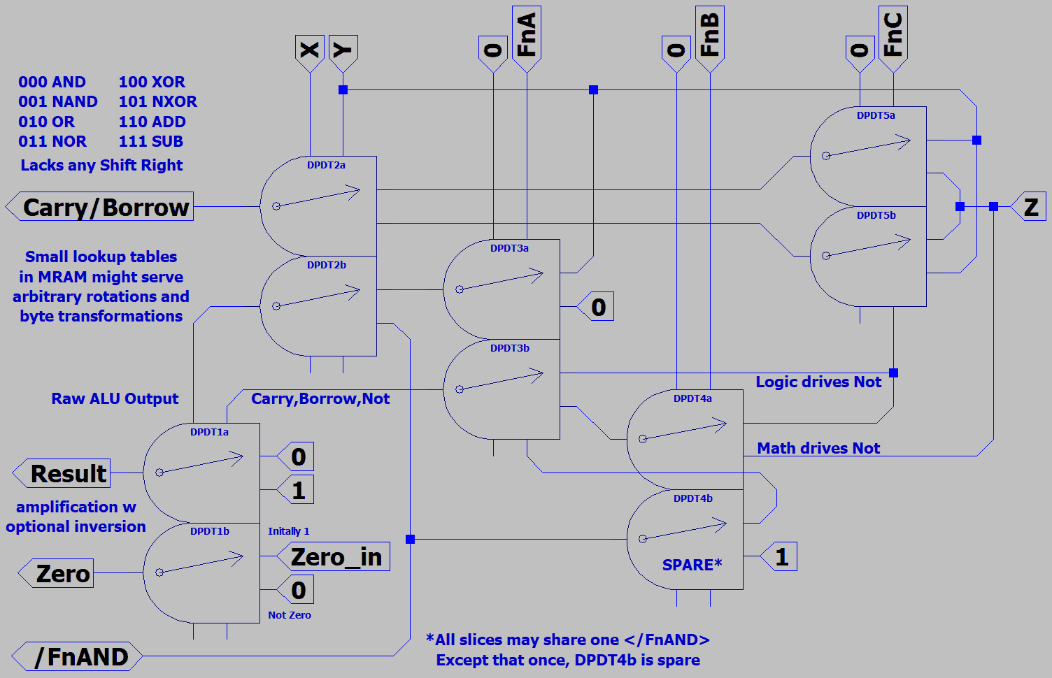
So, counting the small number of working relays I have at my desk, the prototype is not gonna have hardwired shift.
There wouldn't be another slice to shift with anyhow. Back to the ALU only version, dumbed down to use all identical
DPDT, with previously mentioned FnB wiring error fixed.
HotMeltALU.png

Relays, check...
Soldering iron, check...
Wire and solder, check...
Glue gun, check...
Popsicle stick, check...
Dipswitch, check...

12V lamps I don't have, but can patch those in later...
Hopefully the contacts survive a few dry fires till I put
some lamps, transorbs, or MOVs across the coils.
These discarded relays are known to stick anyhow.

-edit-
Corrected </FnAND> from an output arrow to I/O.
Cause other slices won't have don't need relay 6.
 
Last edited:
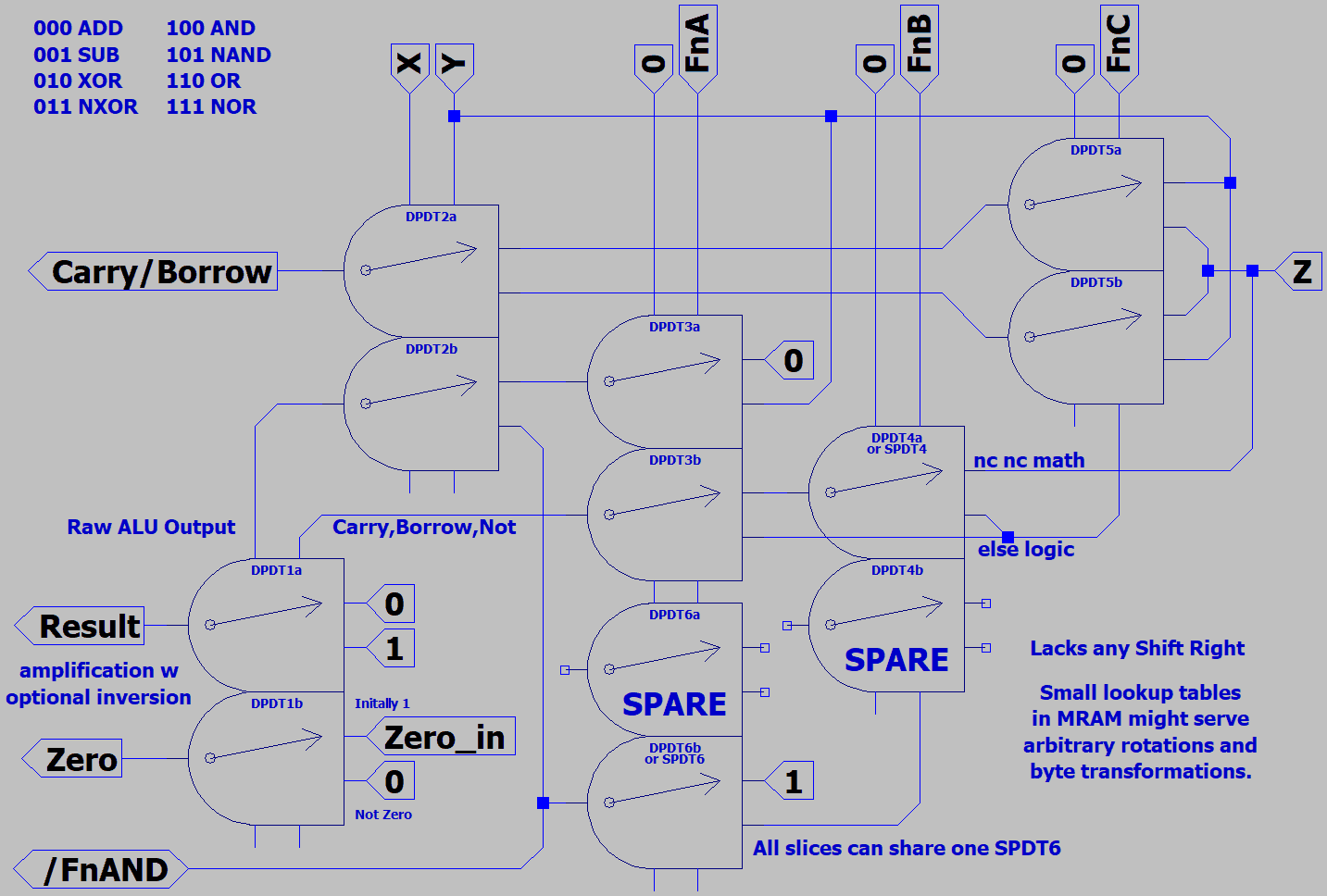
Hardly seems possible, but dropped another relay.
HotMeltALU2.png

Same relay count as before bytewide. But one less if only building a single bit demo.
By rearranging functions to place AND/NAND at 00x, was able to replace DPDT6b
with spare DPDT4b on the B function rail. Relay DPDT6 has now disappeared.

Which sucks, cause I already got six glued down...
Good! Glue strong but not that strong, popped right off no damage.
 
Screwed royally. Dipswitches are SPST. Inputs need to be driven SPDT.
Open circuit is not a valid logic condition in every case I need to drive.
Not suitable for X,Y,Z,FnA, or FnC. Only the FnB input wouldn't mind.
Don't have right switches to fix, don't have enough relays to fake it.

Auto parts might be open/essential? Try there.

-edit-

Back from Autozone and Oreileys. Both had switches and relays.
Unfortunately, none available in quantity >2 or reasonable price.
Light bulbs were also rediculous, without sockets, or both.

So I stopped by my storage on the way back. Nobody was there,
but my card and key still seem to work. Excavated four DIN rails
and some octal relay sockets, but no relays. The big foam tile of
relays I once had or imagined, can't find any trace of it now...

Did find enough double throw switches to get this done, but all
different styles are gonna be a pain to mount even with glue.
I was also sure I had LEDs, but couldn't locate those either...
 
Last edited:
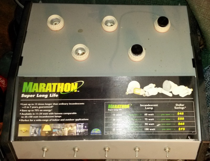
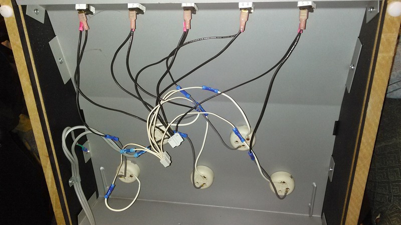
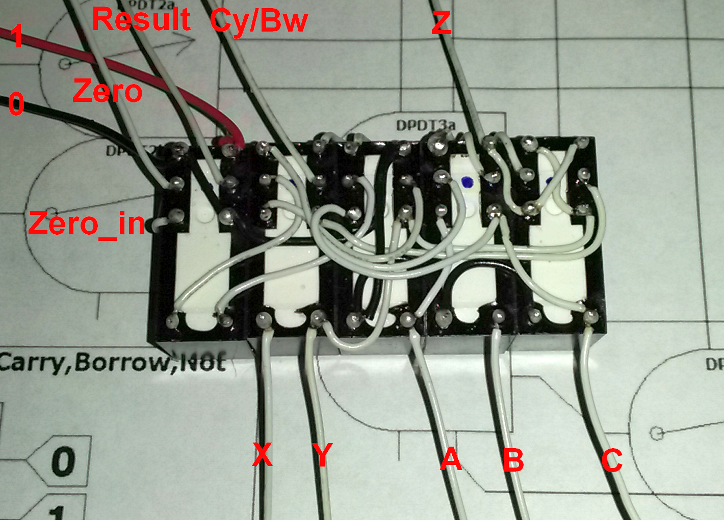
Look what I just found! 1Bit ALU just gained a front panel.
FrontPanel.jpg

BackPanel.jpg

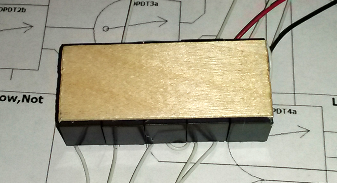
Wrong kind of switch and one too few, but somewhere to hide the popsicle stick and 12V supply.
 
No clue yet if I've wired correctly? I wired for logic levels of +12V (Binary 1) or 0V (Binary 0)
If it works, and scrape up another 12V DPDT relay, I'll build a 2nd slice to demonstrate carry.
As this will be the 1st slice to test for Zero, ripple Zero_in has been initialized +12V True,
which is why it doesn't hang loose like other as-yet-not-connected I/O lines.
Prototype1.png

Genuine dead-bug hot-glue on popsicle technology
Popsicle.png

Front panel switches and 110V output relays (for mock vintage style lamps) are next projects yet to be started.
Open tri-state is of course allowed, just havn't found a purpose for it yet. 110V outputs will likely make use of it.
And coils will want bidirectional transorbs or MOVs if the switches and relay contacts are to live very long.
If I have to do this over, and probably so, I'll give myself more service loop and simply tiewrap the excess.

Might point out that QPDT input switches for FnA,B,C could serve two slices and eliminate three relays each.
But front panel switched logic won't easily expand past 2 slices and can't accept electronic non-manual inputs.
110V output relays could also offload final XOR and elimate DPDT1, leaving us with only DPDT2 in the ALU.
That cheat too would limit outputs to 110VAC. Fine for bulbs, but not the safest logic level for anything else.

All I'm saying is: I could dumb a logic demo box to one relay if I don't care anything but switches and bulbs.
I choose to use all five low voltage relays, so it retains the possibility to drive and be driven like a real ALU.
 
Last edited:
Does not like floating inputs! I knew that, so why did I just confuse the
hell out of myself attempting stOOpid test with several inputs floating.
Expecting function 000 AND, but X vs Y was giving me OR. What???
Operator error...

Turns out a floating Y can go 6VDC and activate two coils in series,
the power bleeds from X. Does not give the same result as properly
driving Y down to 0. Floating X on the other hand, indeed disables
the XOR(X,Y) coil, but then NC makes an unintended path from Y to
the final inverter. Either way: Open vs 12, or 12 vs Open, drives OR
results where AND results were expected.

In brief: Make sure your logic 0 levels are driven to ground wherever
you might have designed something to work that way. At least I didn't
tear it all apart in frustration only to regain my senses later or not at all.

How do two coils in series, that individually want about 7V to activate,
manage to both simultaneously turn ON with only 12V anyhow?
 
Last edited:
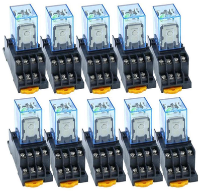
I have on order now, enough nice looking relays with sockets to make an 8bit ALU.
Won't be here till mid June, assuming the donkey cart don't get eaten by a grue
or boiled down for gelatin. AliExpress always a gamble...

Lot10.png
Lot10.png
Lot10.png

30 QPDT relays. Expecting to use 27. DIN rails I already got, and these sockets
look like they got holes to screw down without rails anyhow.

Work on the sloppy one or two bit demo continues. For that, I've a few required
items scheduled next week or 10 days from Parts Express at much higher price.
Switches, SPST output relays, lights, soldering iron tips of different shapes (as I
prefer a chisel, but only have a cone), 12V supply. Barely enough junk to make
the $49 shipping minimum. Seems ridiculous for so little, still better than retail
hardware or auto parts.

I've decided I want to supress Carry/Borrow display for non-math operations.
A computer wouldn't be distracted by irrelevant carrys when doing Boolean
logic. But people seeing logic demonstrated for the first time don't need the
extra confusion.

Order included a 6th output relay for carry supression. Front DPDT switches
will have an unused spare section. FnA and FnB spares can decode the two
math functions that use carry/borrow. Acceptable cheat, since it doesn't do
work for the ALU, just for clarity of display. Don't need the 6th relay strictly
speaking, but prefer no 110V at the front panel. Keep human touch 12V...
 
Last edited:
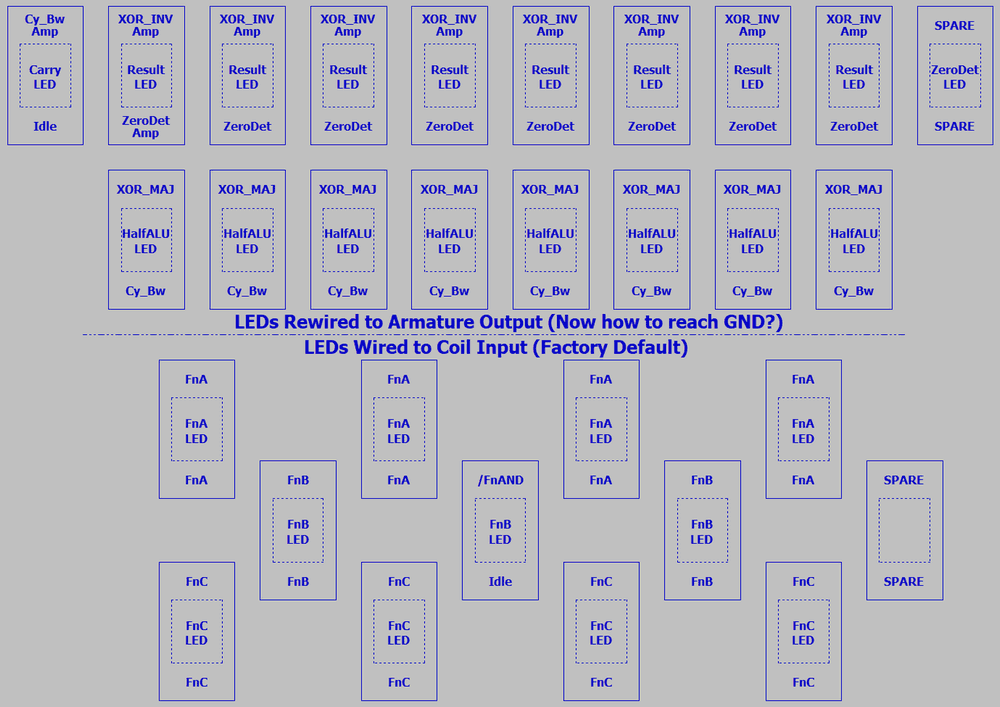
How best to arrange 23 27 relays for 8 bits?

First row of eight might perform XOR(X,Y). If coil LEDs won't
light in either direction, hack to display logic output instead.

Second row of eight coils perform final half ADD or inversion.
Again, resolved logic output from contacts probably makes
for a better display than confusing bidirectional coil inputs.

Third and 4th row relays: Four mux FnA, Two FnB, 4 FnC,
One last oddball relay on the FnB rail may serve to decode
NotFnAND. Unidirectional coil state can drive the Fn LEDs.
Except NotFnAND, will want to observe the logic output.

I may throw a 28th relay at amplifying the final Carry out.

Yeah, that be roughly the plan. Hope those clear lids pop
off without too much effort. Won't know till Junesomething.
There is an LED and resistor in each, I dunno if you can
tell from the group photo above.

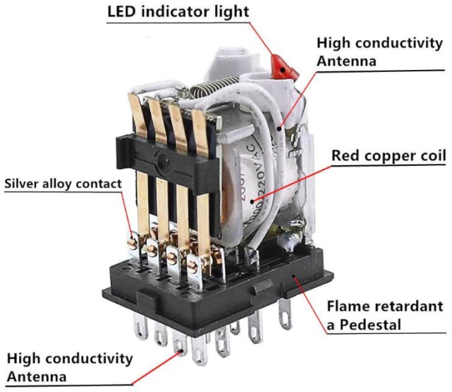
Here's roughly the internals I expect to find:
Antennas.png

Heavens to Murgatroid! High conductivity antennas. LED glows green in other photos.
A flaming retard pedestal must have bitten the head off reds? Quality you can taste.
Accurate confidence. So description. So satisfy...

An unresolved matter: Coils still want MOVs, transorbs, diode bridges, or RC snubbers.
Diode bridge is not my favorite, cause like freewheeling diodes it may slow the release.
I havn't done experiements yet to prove it slows, assuming guesses made in the dark...
 
Last edited:
While QPDT is efficient for rewiring Fn, its overkill for the actual logic.
Entire top half (above the funny dash) could be DPDT for all it matters.
Any of six idle screw terminals could serve to GND the internal LED.
Seems not to be a problem after all (after drawn with that question).

38 unused armatures (not counting intentional spares that don't wear).
No money to be saved ordering a mix of pole counts and sockets to
knock that count down. Just complicates debug and replacement.
8BitAluLayout.png

Just an early draft, time to think on this before relays get here in June.
 
Last edited:
8 bits in just 24 relays. 25 if we amplify final carry output.
But this solution may be confusing relay internal LEDs.
An aggregate of blended functions and mixed bits.

May dumb XY down to display XOR instead. Coils activate
in either direction. An LED might not. XOR vs 0 rectifies.
We can see actual chosen logic results on later relays.

At least ADD is now back at function 000 where I prefer.
Easy increment (ADD nothing plus carry) feels essential.

8bit_Qty24_4PDT.png


There are 16 wasted armatures at the result inverter
assuming all identical 4PDT. These might yet prove
handy for other logic levels. 5V, 120VAC, whatever...

I has this down to 23 relays earlier by decoding ADD.
But discarded because it added a step of mechanical
ripple to the result. Not sure I saved a picture. Just a
different way at the bottom to Mux the final inversions.

Wishing for a way to supress carry/bw output without
passing through two more underutilized relays or the
previously mentioned objectionable delay to decode
and operate by FnADD/SUB instead.

Could throw three automotive SPDTs at the problem.
One amp, two divert to GND by FnA FnB? Ug, yuck.
Something better will surely come at an inconvenient
moment for writing it down.

Qty100 Bourns 18V MOVs now onway from Allied.
Closeout for 10cents apiece. Next week or so...

Exit cluttered by ugly automotive relay bandaid
as necessitated by obsessive feature creep.
8bit27Relay.png


Now can I replace NXOR with rotate right or similar
function and still build with just 30 relays? Maybe...
 
Last edited:
Only the most significant bit need distinguish between these operations.
Other seven bits can save logic by treating all march to the right same:
Rotate right circular (8 bits sans carry)
Rotate right through carry (9 bits)
Arithmetic shift right (duplicate MSB)
Shift right (padding with 0)

Y isn't doing anything. Shift could pad with Y rather a than hard zero.
Or Y could choose the shift style, maybe saving a function input for
some other operation where Y is busy.

Also rediculously similar. Except the way carry and borrow propagate.
The first three are absolutely identical. And the last simply ignores Z:
ADD X+Y+Z
SUB X-(Y+Z)
RSB Y-(X+Z)
XOR X,Y

Once you grasp Majority, AND and OR are the same operation too.
And I only just learned that stupid chain and double coil bar hanging
from my grill was for holding a match. Incase the igniter might fail...
 
Last edited:
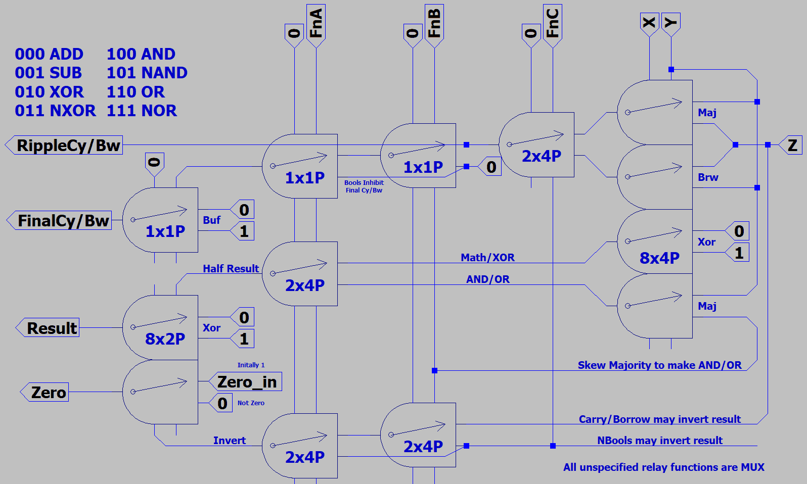
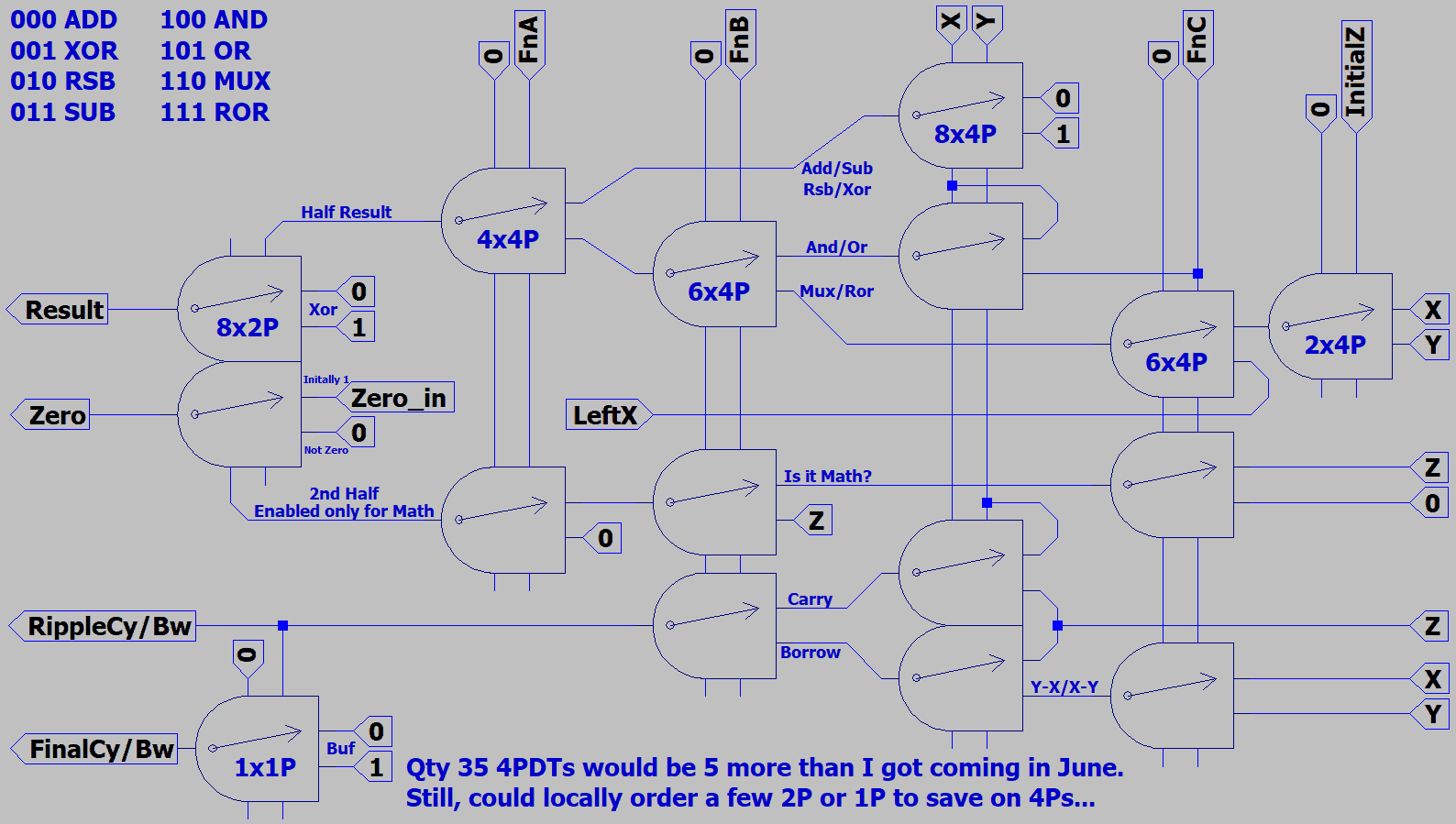
Now that I've saved all those relays, let's mess it up by adding more.
If I could have only eight primitive functions, which are most powerful?
Any tricks to pare this down to the 30 4PDT I've already got on order?
NewRelay.png

NAND/NOR/NXOR dropped. Not terribly useful, but they did make for a simple circuit.
When was the last time I cried, "My kingdom for a NXOR?!?!?" Other than just now...

If not clear what RSB means, its "reverse subtract". You know, Y-(X+Z).
Darn useful if you got brief instructions that exploit an accumulator.
Otherwise waste time juggling arguments.

If not clear what MUX does, its a conditional. Let carry flag select X vs Y.
Should be many entertaining ways to abuse this.

-edit- Oops! Had 0 and Z swapped over on the right side. Drawing fixed now, probably.
-edit2- ROR is gonna have to be rotate right circular. There is no problem for LeftX to
tap the carry input to figure the new MSB, but totally forgot to wire a path to rotate the
LSB out to FinalCy/Bw. Not satisfied at all with this version of the drawing...

I should check on my deliveries tomorrow. At least Parts Express ought to be there.
With switches and output relays, I might be able to finish the 2bit demo. Allied might
even have sent my MOVs. Other essential and official mails I need to pick up too.
Not talking about 30 quad poles in sockets. Those come later, slow boat later...
 
Last edited:
Everything is here, everything. Not mid June, but now, mid April.
Relays, switches. Also 18V MOVs from Allied, and misc junk like
soldering iron tips from Parts Express.

Ali to EMS to UPS, I don't know exactly what magic was involved.
Only know: I didn't pay for special handling. Do they read [H]?
Genuine ONRQM too! No intent to confuse w inferior OMRON.
Perfect coils vary wildly from 120 to 145 Ohms, .2 to .25 Henries.
Regardless: All activate around 9V, deactivate around 4V.

RelaysOnSocketsOnDINrails.png


MOVs tested w 10 Ohms in series got toasty near 28VDC.
On relay, they clamped flyback spikes to about -20VDC.
Sorry, I didn't think to save a scopeshot of that spike.

Sockets feel janky, but look nice on old rails I already owned.
One had something rattling inside, turned out to just be plastic.
You do not want to take one of these socket puzzles apart.
Terminal backing nuts do seem like they could fall off inside.
Not much prevents it, but thin fingers of brittle plastic.

Also my 12V supply is only good for about 2A. I measure these
coils at 100mA each. I need 3A supply if all were to activate at
once. More with extra lights. The built-in LEDs are pretty dim.
I'm sure I have small supplies in storage that do at least 5A.

Can't even jump fully into this project immediately. Thought I had
plenty of time to deal with RL troubles first. Duplex nazis and stuff.
 
Last edited:
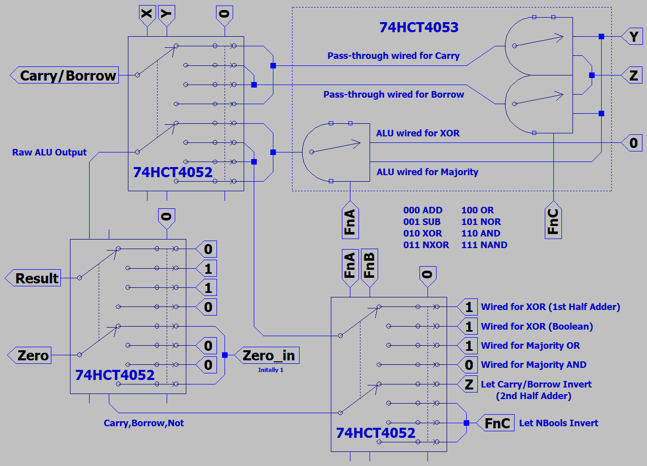
While we are still *ON* for relays, its important to remember that this isn't about relays.
Its about a simple Majority Logic ALU that might later port to quantum. But for fun lets
also pretend a quick port to CMOS. Turns out thats not too difficult...

74HCT4052_53ALU.png


I havn't yet drawn a symbol for 4053. For now, a hodgepodge of old symbols in a dashed box.
Probably use a pair of 4052's instead, and see what can be done for adding the three upgrade
functions I had wished for earlier.

-edit- Inputs to top half 4052 at the lower right reference only constants. Therefore we do not
need to repeat this fragment for every slice. There are much wider ?PDT to be found among
video MUX than 4053. I'll Quote specific parts later, I left my PDFs in a folder at work. -edit-

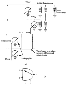
You might recall the DGate symbol I use was originally Goto's. Intended to represent a VAQ,
or variable activation quantum flux parametron. What isn't clear to me is wether VAQ is a pass-
through multiplexor that works much like a double throw relay w some parametric amplification.
Or if it has exponential gain and latches until powered off like other parametrons? If it latches,
a relay style instant ripple might not function as intended.

VAQ.png


I can't reasonably build an actual VAQ to find out by experiment.
Might try with oldskool LC parametrons, but those I am more or
less sure would latch up without some missing unknown trickery.

Even if I figure the secret tomorrow, building the relay demo comes
first. Why? Cause relays look cool. Does everything need a reason?
 
Last edited:
So, I've had all the parts for a while now, thats not gonna fly as an excuse.
I've also had the week off and done almost nothing useful with it but sleep.
But I did clear a little space on top of the freezer to set everything out and
motivate myself to start construction.

During the time I was doing nothing, some random thinking did take place.
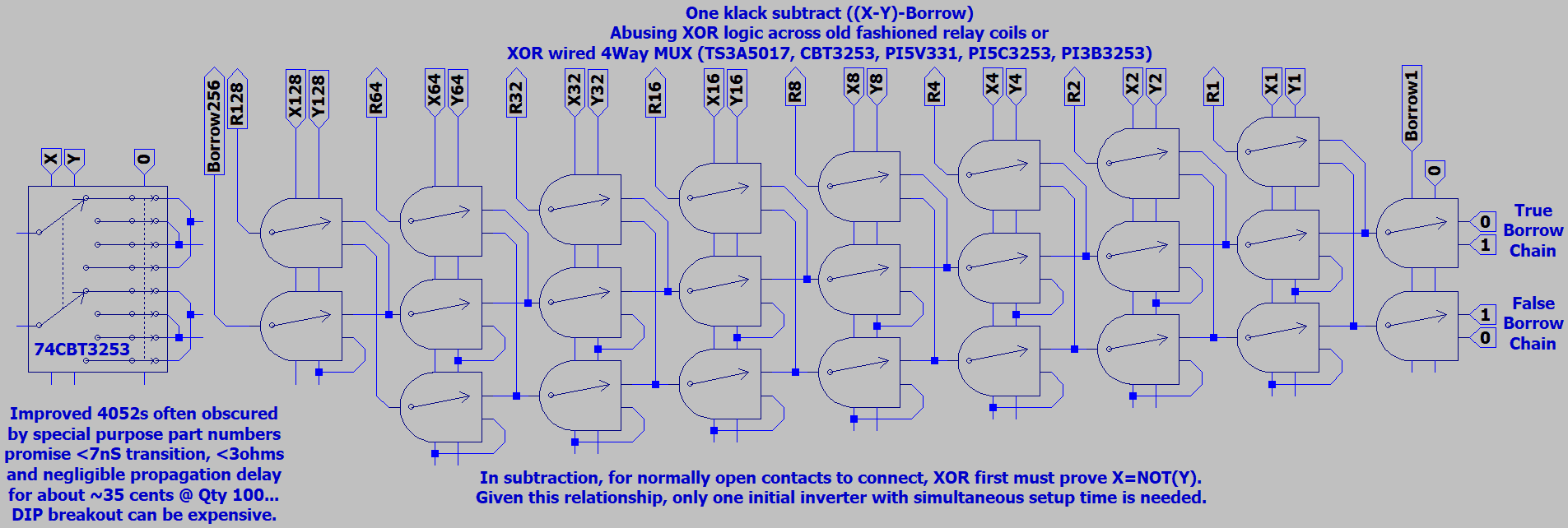
One of those ideas I drew, so as not to forget. I found that subtraction can
be accomplished entirely in one simultaneous movement with fewer parts
than addition.

Subtract.gif


Thats just 9 4PDT relays for the whole byte and borrow.
Not even using every switch. If unclear what was special
about this circuit, both the result and borrow immediately
pass thru. There is no extra wait to setup a second XOR,
or half subtract.

Only in subtraction is Y garaunteed to differ from
X exactly when both X and NOT(X) are needed.
Coincident with each failed propagation of borrow.

Won't be updating the 2bit ALU to take full advantage.
Already built and tested one bit, no reason to fix what
ain't broke. Just finish the job to the original plan.

Might or not find its way to the 8bit demo later, cause
this way of subtracting doesn't give the same speed
advantage or part savings when adding. Not without
another XOR, that subtraction could fake for free.
 
Last edited:
Here's what I come up with to ADD in 1 Klack, no wait for 2nd half-adder.
In 74CBT3253 form, that might be <7nS, compared to two stages <14nS.

Uses driven logic low, yet one less pole than Konrad's with open low.
Figured I could do something useful with that spare. NSUM volunteer'd.
Nsum isn't doing anything useful now, but might in ALU form later.
Not yet sure all other needed functions integrate well with this plan.

Asking carry chains to drive a large fanout of results could be a tough
load. May slow more than 7nS theoretically saved by inverting during
setup time. Fake inversion by swapping lines thereafter is definately
not a simple way to evade further delays, and gives no buffering.

ADDSUB_Fix3.gif


-above is my third hopefully correct edit of the drawing-

Looking at this fresh, I can see that carry vs ncarry make a well balanced twisted pair.
So too does P vs /P. However G vs I is imperfect. That might be fixable as a twisted
trio together with P. Might also help to dummy load nsum to insure balanced currents.
 
Last edited:
Lease Nazis have expended the limits of my patience for unlimited greed.
So forget any practical builds any time soon. All going back to virtual and
theoretical till I figure how much shop space I can afford somewhere else.

Anyways, the wheels of invention keep turning no matter what trouble
demands my immediate attention in foreground. Here's what I got lately.
Consider four flavors of switched carryborrow chain...

1) Default rule is propagate the flag through all slices unchanged.

Let each function's truth table decide to obey or ignore the chain.
Don't make it the chain's business to supress itself when irrelevant.
Let there be exceptions, that attempt a Ninja Swap at each slice.

2) In the case of A+B, where XOR(A,B)=0, switch out the propagating flag for B instead.
3) In the case of A-B, where XOR(A,B)=1, switch out the propagating flag for B instead.
4) In the case of B-A, where XOR(A,B)=1, switch out the propagating flag for A instead.

What does this look like in a schematic?

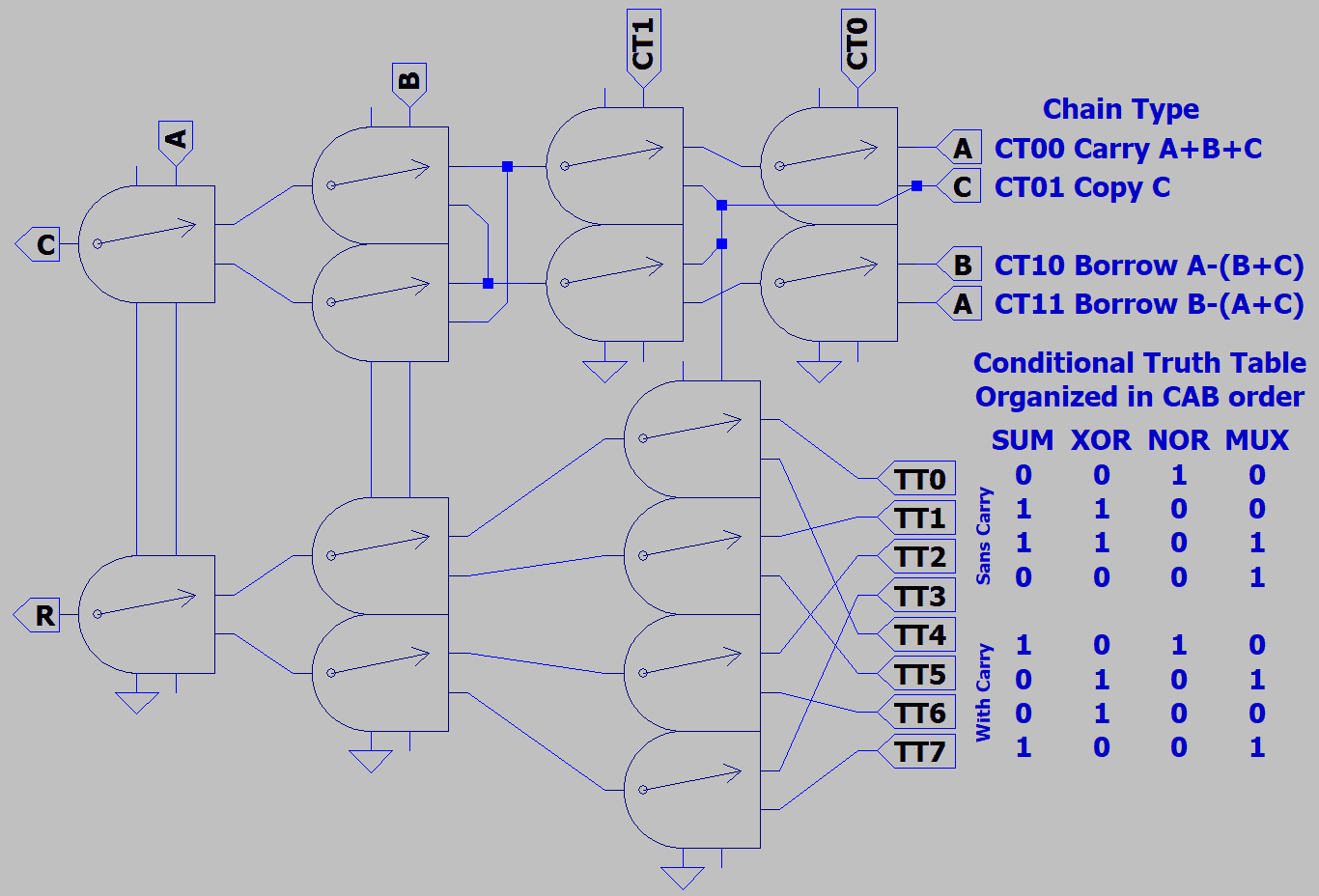
5RelayConditionalALU.gif


Or with 8way multiplexors, even easier...

EvenDumberIdea.gif


The chain are two MUXs on the left. Truth table is MUX on the right.
Make sure they are switched through types, not combinatorial logic.
74151 might have the same pinout in theory, but gates in the path
would slow this switched chain down to ordinary ripple. I think this
one falls under the topology of carryskip adders? But seems a very
strange case, since it skips by virtue of switching, not by skipping.

What needs clarification now is the structure of the truth table.
An 8 way table depending on X, Y, and maybe the Carryborrow.
***Yeah, I realize it was all in terms of A, B just a moment ago***
The result may depend on carryborrow only if the table says so.
The chain never depends on carryborrow, only switches it.

Addition, Subtraction, and Reverse Subtraction all truth NXOR XOR.
Thus the carryborrow chain's conditon may invert a final SUM result.
Note: SUMs figure the same way only when borrow is non-inverting.

The AND function, which should not be conditional, truths AND AND.
Thus doesn't matter what old flag or nonsense the chain might pass.
Default chain behavior rather conveniently preserves an old flag that
AND need not touch.

Other conditional functions are possible. So many, I don't see how
it simplifes to list all 256 in accidental order. Better to understand the
process, as its simpler than the result. If we examine each case of
carryborrow separately (Sans Carry vs With Carry), that might help.

1100 X input
1010 Y input
------------------
0000 ZERO
0001 NOR ( X , Y )
0010 AND ( NOT ( X ) , Y )
0011 NOT ( X )
0100 AND ( X , NOT ( Y ) )
0101 NOT ( Y )
0110 XOR ( X , Y )
0111 NAND ( X , Y )
1000 AND ( X , Y )
1001 NXOR ( X , Y )
1010 Y
1011 OR ( NOT ( X ) , Y )
1100 X
1101 OR ( X , NOT ( Y ) )
1110 OR ( X , Y )
1111 ONE

Accidental truths with one input inverted may be of limited utility, but I list them anyway...
Also had to pad extra spaces to avoid triggering unintended emojies. ( Y ) (y)

Rotate right and zero detect still want for separate solutions.
 
Last edited:
Just realized that X and Y are constants at each demultiplexed position!
Each chain switch then corresponds to a Propagate, Generate, or Inhibit.
My head stuck in Majority Logic maybe kept me from spotting this earlier.
No reason inputs should drive outputs where amplified constants are free.

WithPGConstants.gif


-edit- Slight mistake in the drawing above. Carry should feed the next bit's truth table, not the current one.
Chain Types 1,2,3 should be re-drawn to sit at the left. Chain Type 0 can stay where it is, but break into
four sub-types of arbitrary logic injection: PropagateUnchanged, CircleRight, Rev<>veR, PanelSwitches.
Conditional truths can then be setup 11110000 to output the chain as-is without regard to X vs Y. Some
unshown extra MUX might be needed at the far left of the ALU to insure the proper bit rotates out. -edit-

Carryborrow chain setup can happen in 6nS for all slices in parallel.
Let the flag propagate through switches at 0.25nS per slice (x16?)
That's maybe 4nS. Another 6.25nS to set and pass truth table results.

I'm thinking 16.25nS may be considerably faster than the worst cases
for 74F181 with 74F182 lookahead. Not penalizing 74F181 for time to
detect zero, since mine can't do that. Still, a lot more parts to wire up
than the classic solution. New conditional functions might be worth it.

Sadly, there don't seem to be any fast switching 16way MUX, so its
probably at least 3 chips per slice to do this all in 8 way. Or 4 ways,
provided /OE style allows for independent control of dual 4:1 MUX.
Some 4way have all or nothing /OE behavior, read your spec sheet!

AllOrNothing.gif


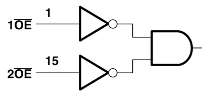
Dunno how an all or nothing NOR of /OE's was considered useful.
Maybe some differential pair had to be enabled in precise unison?
More precise than simply hardwiring pins 1 & 15 together? Those
pins are like 1/4 inch apart on a PDIP. Whatever, just be aware that
you might not easily merge dual 4 ways without independant /OE's.

All or nothing:
https://www.ti.com/lit/ds/symlink/sn74cbt3253.pdf
https://assets.nexperia.com/documents/data-sheet/CBT3253.pdf
Independant:
https://www.ti.com/lit/ds/symlink/sn74cbt3253c.pdf
https://assets.nexperia.com/documents/data-sheet/CBT3253A.pdf
https://www.diodes.com/assets/Datasheets/PI5C3253.pdf
https://www.onsemi.com/pub/Collateral/FST3253-D.pdf

Not an issue for true 8 ways, as they only have one /OE.
 
Last edited:
8WayMUX.gif


I'm figuring worst case propagation delays of 74CBT logic. Compared to 74F181 + 74F182 + 74F21.
Carry Look Through smokes Carry Look Ahead by more than 7nS. Carry ready in 10.25nS vs 18nS.
Results should then be ready in 16.5nS vs 26.5nS. Zero known in 26.5nS vs ??? I've got Zero in the
same time F181 has only progressed to Results.

I'm not sure what to make of F181's time to A=B. Fairchild's spec sheet sais an extra 27nS, but that slow
doesn't make any sense. If its total time, not add-on, that implies logic slighly too fast to make any sense.

-edit- Two spec sheets of other mfg agree, the internal AND that figures A=B was absurdly slow.
The reason is open collector. All 181 A=B's can be tied directly together and pulled up by a single
resistor. Nothing prevents using much faster external logic instead, 74F21 perhaps. From results
at 26.5nS, that's two stages of 4Way AND at 5.1nS each = 36.7nS to a final Zero -edit-

What I wouldn't give for time to build this. NanoCenturies (very nearly Pi seconds each) are not enough...

-edit- If I swap Borrow's I and G constants for function inputs, I could have reverse subtract too. -edit-
 
Last edited:
Just noticed a strange coincidence regarding 74181 that maybe isn't coincidence.
My table of half truths exactly replicates all 16 non-math functions of the 74181 in
a completely different sequence. Not by thoughtful intent, only discovering it later.

I havn't found an obvious way to translate my straightforward sequential table of
truths to S0 S1 S2 S3. But in some sneaky way, could also be how 181 worked?
Need to investigate how combinatorial AndOrInvert gates may have been used.

Ken Shriff mentioned something similar over on Stack Exchange (sorry lost link).
Further stating that 74181 maths could all be explained as A plus fn(A,B) plus C.

-link found-
https://electronics.stackexchange.c...ing-for-the-arithmetic-functions-on-the-74181
 
Last edited:
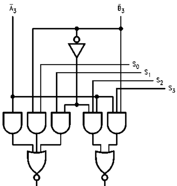
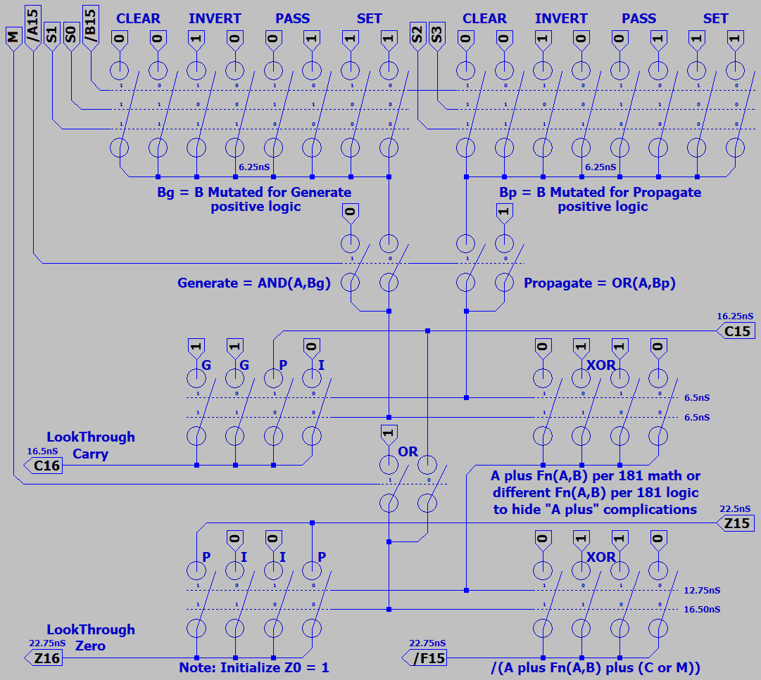
Damn 74181. What a struggle to understand it.

181MUX.gif


Generate is the AOI on the left. This output is active when high.
Propagate is the AOI on the right. This output is also active high.
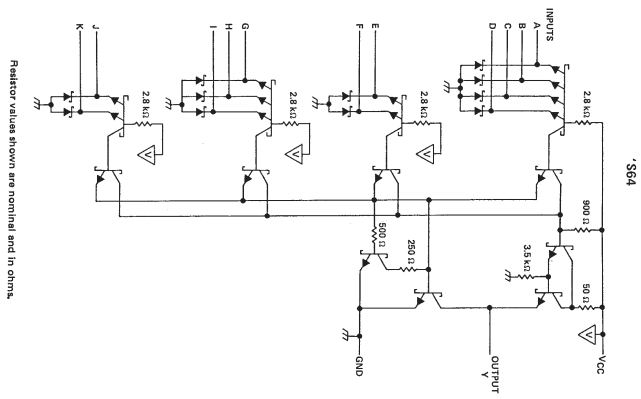
Look up a 74S64 AndOrInvert gate if you want to see an AOI's
internal schematic. Do-nothing AND gate at far left represents a
necessary input transistor with only one emitter.

I've re-oriented an S64 schematic to better aproximate the 181.
Input counts aren't exactly the same. I coud find nothing closer.

S64.gif


When /A is 1, it inhibits Generate and enables /B to inhibit Propagate.
/A doesn't do anything else. None of the S inputs directly affect /A.

/B is where things get interesting:
S1 vs S0 may 00 clear, 01 pass, 10 invert, or 11 set /B as used by Generate.
S2 vs S3 may 00 clear, 01 pass, 10 invert, or 11 set /B as used by Propagate.

The 16 functions come of a XOR gate that mixes Generate vs Propagate.
That XOR got cropped out of the 181 drawing, I might edit it back in later...

Still don't fathom how XOR derives the same 16 functions as a straightforward
4Way truth table, but now see why it seems scrambled. Only 16 functions are
possible without Carry, which comes optionally later. Any method that manages
to cover all possibilities without repeat is garaunteed to populate the same list.
 
Last edited:
4Way truth tables make a simpler and faster ALU in one less step. But if functions need
to be 74181 compatible for some reason, how might MUX quickly replicate dual mutators
of B before XOR mixes P vs G to make a HalfResult of 16 logics? Aside from abusing a
ROM+SRAM cheat-sheet solution. Let's consider [H]ard logic first...

MUX181_RevC.png


This is a newer drawing than was originally posted. Comments added, errors fixed.

Theoretically faster than any 74181 and most SRAM. I think Half and Full Results
may yet be merged to one process and save another 6.25nS. But not sure how to
lookthrough Zero in parallel if I did? Lookthrough Zero should be simultaneous with
/F results. Even dead bug relays hot melt glued to a popsicle stick had that feature.
Rather easy as long as your final operation is XOR, as 74181 also happens to be.

C15 is also accesible as an overflow flag, not externally available with a real 74181.

Merging Half and Full Results into one process with an 8 Way MUX might not be
any faster after all. Realizing now that such a MUX could produce no result until
6.25nS after lookthrough carry is ready, exactly the same. I need to think on this...
 
Last edited:
I look back to my Truths ALU. Its not significantly faster or slower, just different.
But I see in both a trend that requires a cascade of no less than three delays.
A delay to figure the carry. A delay to figure the result. A delay to figure zero.
Can't find a way to parallel these delays without creating another in its place...

Suppose we throw the entire concept of a Zero flag out the window? You could
decrement any result to test if it throws Borrow. So direct detection of Zero was
clearly never essential. Especially if its been slowing every other operation that
may not have cared to know about Zero. 27nS extra for 74F181 open collector.

What if we instead detect A=B immediately, before or in parallel with other initial
tasks? I know that cheat is not the same as detecting a Zero result, but it could
be ready much quicker. But is A=B a useful fake Zero? Or would it force to rely
upon the Borrow workaround too often, and waste more time than saved?

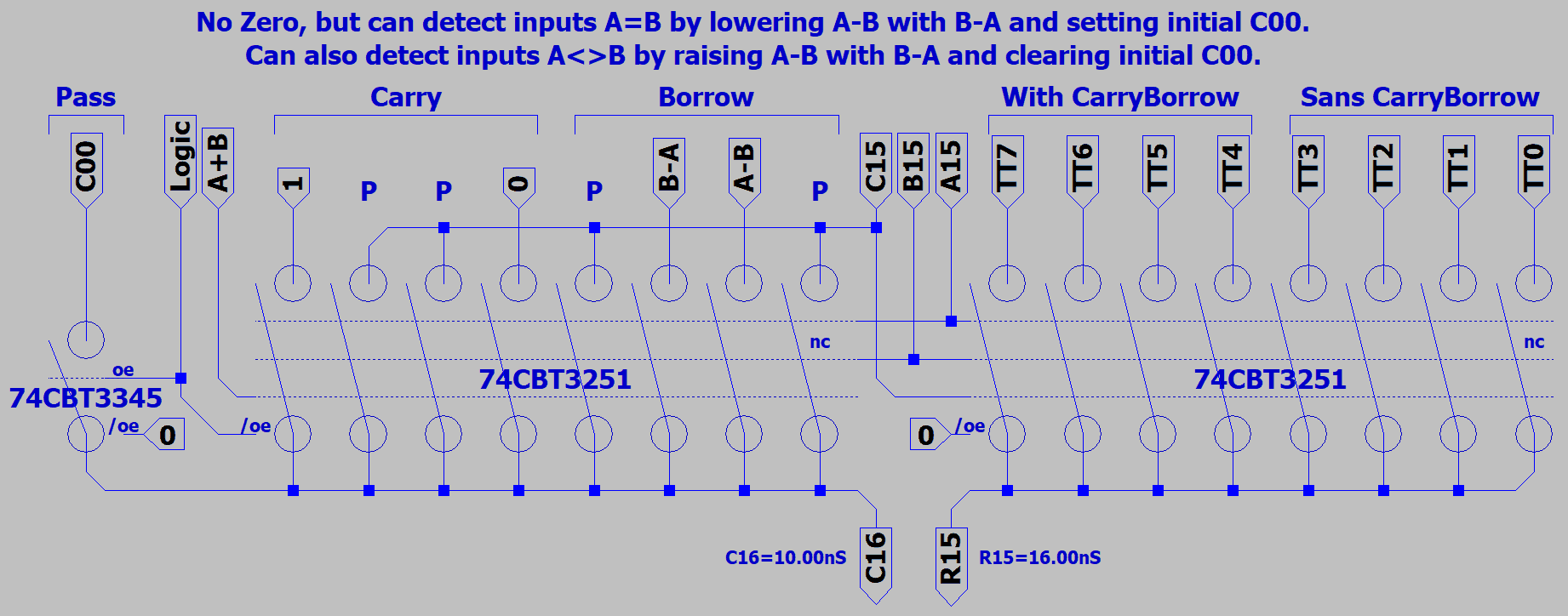
FastFakeZero.gif


Now that I look back a day later, it seems the Borrow chain
was aready capable of detecting the initial condition A=B.
The extra four way could easily be omitted. Simultaneously
pull control lines A-B and B-A low, and raise Borrow.

If A=B, lookthrough would observe Borrow as initially set 1.
If A<>B, then Borrow gets replaced by either control line 0.
Or could initialize with a clear Borrow and let exceptions
raise the flag instead.

If A=B teamed with XOR XOR Truths, it would also reveal
exactly where mismatches (if any) occured.
 
Last edited:
Trimming any legacy that might slow it down, 16nS!

Logic operations use 2x 74CBT3345 (8 Pole Single Throw) to broadcast an initial carry to all truth tables, and output that carry unchanged.
Detecting initial A=B or A<>B would be a Math operation, where Borrow becomes a weak but extremely fast substitute for final Zero.

The truths for addition and subtraction remain the same: NXOR,XOR.
Useful truths for A=B might be XOR,XOR to see where mismatches occur.
Comparisons intended only to test CarryBorrow may prefer non-destructive truths such as A,A or B,B.
Say we subtract A-B, with twin truths that preserve A. Next op might be condtional truths B,A. Giving us the larger of A vs B.

SansZero.gif


Still wants for rotate right of some kind. +.25nS for an arbitrary rotations mux
at the head end of the carry chain. PASS mux width would expand to match
and want a few more control signals. Rotations should maybe keep separate?
But still looking at same +25nS to pass, clear, invert, or set carry at the head
end which is almost certain to be worth having.

Also need to insure break before make between competing OE's.
Won't do to have C00 briefly short other constants or functions.

I am confusing hard over some of the available multiplexer options.
There's a charge pump feature (simple voltage doubler?) on some that
lowers Ron by raising gate voltages beyond the rail. That might make
for faster MUX, except there seems to be about 10 to 20MHz limit of
how often you can switch without overwhelming that internal pump.

Whats the point of a MUX that could theoretically switch fast enough
for 63MHz, but wheezing insuficcient magic blue smoke at 20MHz?
 
Last edited:
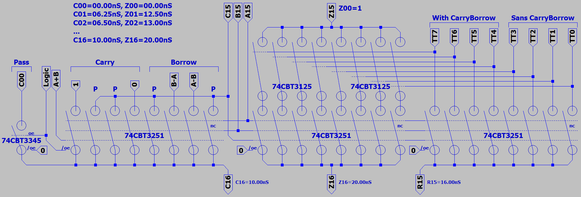
At least one way I've found to setup Zero switches in free parallel time with Result switches.
But propagation through a chain here of 32 switches adds delay, even just .25nS per switch.
32 extra components only beating the prior best time to a final traditional Zero by 2.25nS.

AnotherLameZero.gif


Another impractical way might be to detect current drawn by the truth table inputs.
Fake zero was not only faster, it also didn't need extra parts.
 
Last edited:
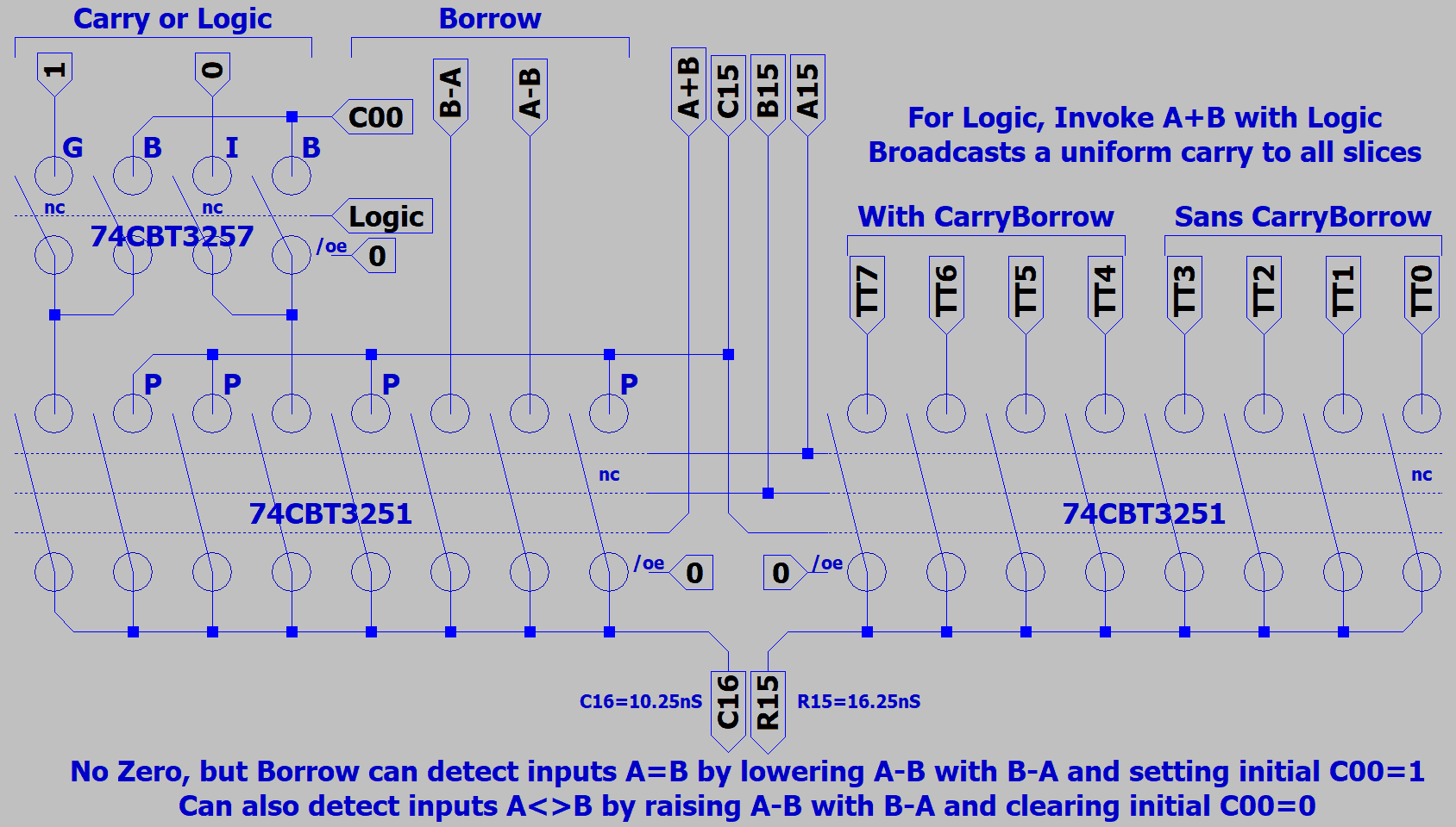
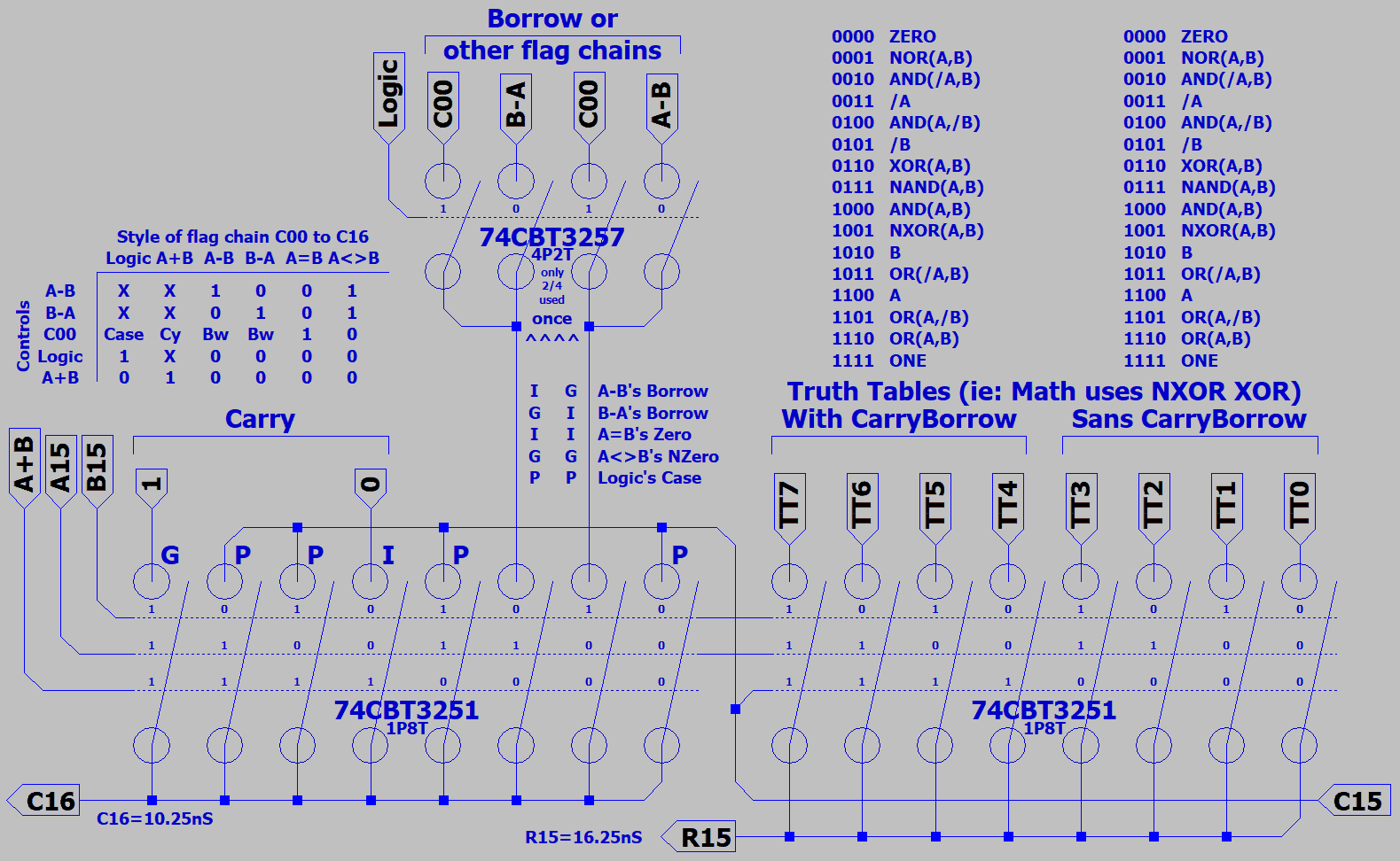
Suppose C00 might be Broadcast in place of A+B's Carry Generate and Inhibit constants.
One instance shared by all, not repeated per slice...

Could turn A+B's Carry into PASS with four switches instead of 16 and eliminate any OE
timing conflicts. Will add .25nS to worse case, though /OE might have wasted the same.
Seems /OE is not quite as fast as S inputs by about the same as 1 through-switch delay.

LessIsMore.gif


Magic decoder ring for the CarryBorrow chain: P=Propagate, G=Generate, I=Inhibit, B=Broadcast
Broadcast trick is only useful when C00 everywhere on the chain would be same as Propagate.
But keeps the chain brief while patching-in A=B , A<>B features.

Later decided B=Broadcast was a poor label. Too easily confused for the B input. Just call it P.
 
Last edited:
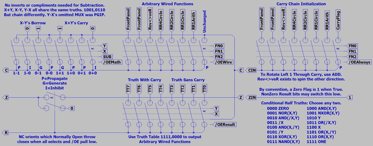
No innovations. Just cleaning up the drawing and documenting how it works. We are looking at the very last slice of sixteen. Delays include fifteen earlier slices not shown.
Dude at work knows his 181, but couldn't make sense of my drawing. In particular, unable to determine poles or throws from just "NC". Trying now to provide clearer hints.

MoreOfTheSame.PNG
 
Last edited:
If we consider the borrow chain by itself, we have a magnitude comparitor!
Two newly noted comparisons were possible in the drawing above as well.

MagnitudeComparator.png


10nS if we stretch this out to 16bits, assuming 74CBT. Unlike other comparators that simultaneously compare in several ways,
Borrow gives one comparison of whatever type was setup. Not a horrible limitation, considering the usual next step would have
been further delay to filter a single chosen answer....

Top and bottom switches Propagate toward the left an existing Borrow on ambiguous subtraction and comparison cases 0-0 , 1-1.
Middle switches 1-0 , 0-1 discard an existing Borrow and Replace to the left with whichever functional constants were selected.
Discard and replace with a constant may be more familiar to you as Generate or Inhibit.

Was only after I'd drawn the Borrow chain a few different ways in search of clarity and fiddling with charts that I noticed certain
controls I'd used before had absolute affinity for GT LT EQ. Thus "B-A" evolved to become GT, "A-B" became LT, and "C00" EQ.
In comparator context, the latter describe exactly which comparison combo will rule. LT with EQ meaning "Less Than or Equal".

Classic 74F85's worst case for 4bits was 14nS. Wired as a pyramid of 5 F85's, a 16 bit compare would have taken 28nS.
We don't strictly need A=>B A<>B A<=B, since they are very simple inversions of A<B A=B A>B. I think a CPU could be
made to use either set with no feature or speed disadvantage.

F85 is combinatorial, not a chain of Borrows. It doesn't break out in way that could save half the work of subtraction. I didn't
draw subtraction taps on my chain either, but they aren't difficult. Taps W1 W2 W3 would be located at three vertical busbars
between multiplexers, and W4 is the main output. EQ input is W0, if you hadn't figured that already...
 
Last edited:
The other new again old thing is a simple but very fast +1 for program or microcode counting.

Counter.png


Konrad would recognize his differential carrys.
 
Another way to sequence microcode without waiting for carry is to let cellular automata generate your count in pseudorandom sequence.
Might lose use of one number like 0000 or FFFF that locks or kills all cells. Store microcode in funny sequence. All invisible and very fast.
https://en.wikipedia.org/wiki/Linear-feedback_shift_register
https://hardforum.com/threads/c-random-number-question.1958763/#post-1043611587

MUX above might add +1 incredibly fast, but doesn't solve problems of latching the output, feeding it back, or controling the cycle.
Using a shift register solves most of those problems. Where a scrambled counter could work, it may be the simpler faster solution.
Not saying expose such a thing as the program counter, indexing would become way too confusing.

Wouldn't be absurd to use both types in the same machine. Scrambled for microcode, +1 for Program Count.
As microcode enables controls that allow a normal PC register to count and branch, somehow also has to self count.
A third solution is store the next address in each line of microcode, and not count at all. Maybe the lower four to six bits...
 
Last edited:
Back
Top