d0wnjumper
n00b
- Joined
- Jul 12, 2017
- Messages
- 3
RGB is life!
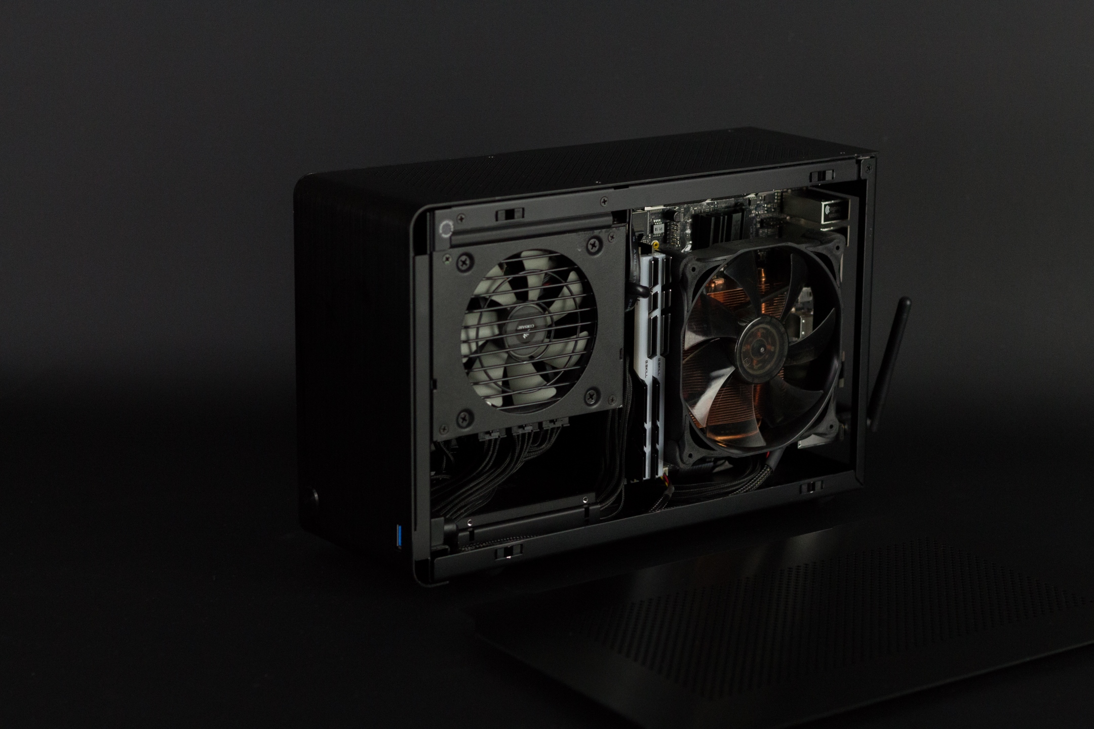
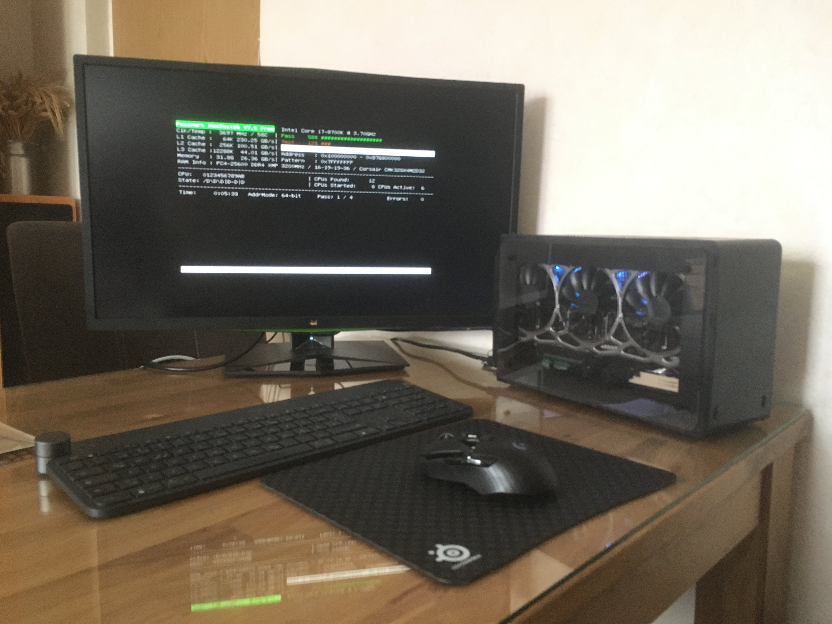
Installed 2 Cablemod Aura-sync compatible LED strips, one 30cm above the GPU and one 60cm around the motherboard. Made my own extention cable to connect the 2 strips.
I'll take a new video when it's dark
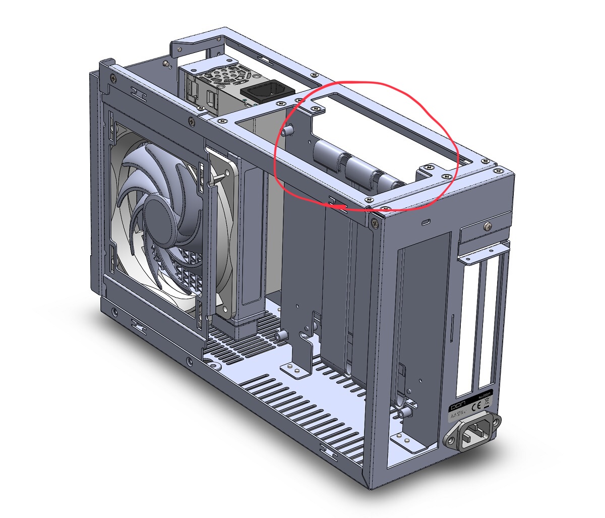
sldr, is it possible that you tell me where to buy the m2 standoffs (male) and what length the standoffs have? Thanks in advance!
")


")