Zarathustra[H]
Extremely [H]
- Joined
- Oct 29, 2000
- Messages
- 38,866
Hey Everyone,
I'm seeking some advice from someone more seasoned than I am with electrical signaling in order to avoid long and costly trial and error.
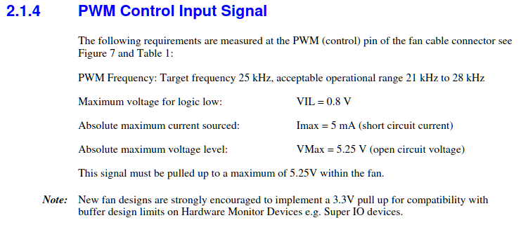
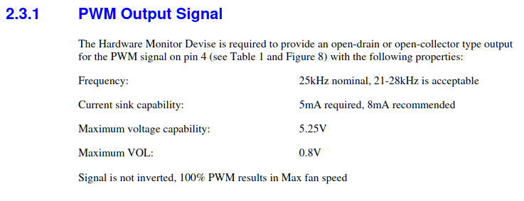
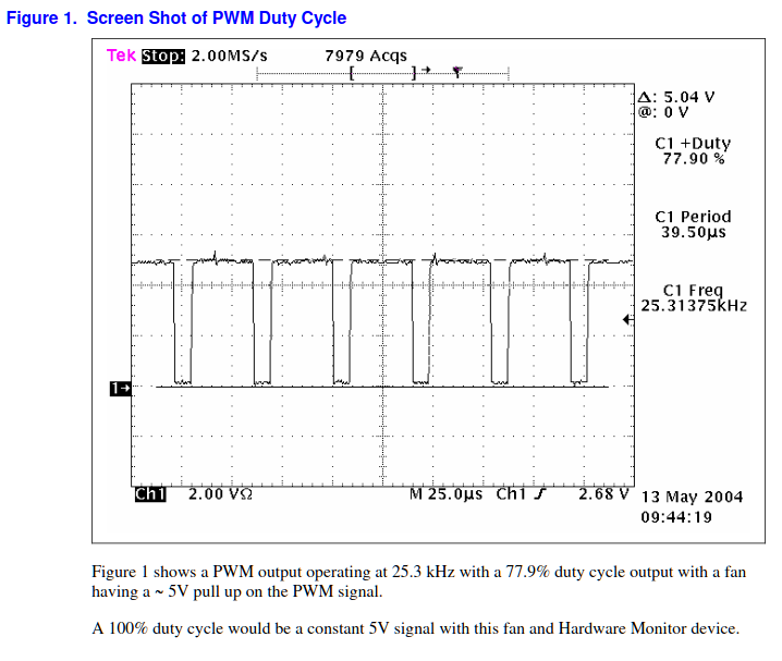
I'm working on a sneaking little custom project that is going to require me to route 5v PC PWM fan control signals a long way, maybe ~50ft.
I've done stuff like this over shorter lengths, so I know PWM signaling can withstand some unusual implementations (you don't actually need the power or ground wires, you can just run PWM on its own and it will usually work, provided you have power on the receiving end)
So, my question is what the best way to accomplish this might be.
Some thoughts I have had is to use cat7 cable, chopping off the connectors and soldering my PWM signal to some or all of the leads inside, taking advantage of the twisted pair benefits for protection from noise.
But the leads are very small gage, and I wonder if the voltage droop will be too much over that range.
My second thought was to use solid copper core electrical wire, the type you use to wire your home for mains power. This has a lot less shielding, but the thicket conductor should result in less of a voltage drop.
I used one of the many online wire gage calculators, but this is guesswork, as I have no idea how many amps the pwm signal represents (probably very low) and how much voltage I can afford to lose before the PWM signal no longer works.
If I enter 5v 0.1 amps and allow for a voltage drop of 5%, it tells me 14 AWG is sufficient. Does this sound reasonable? Maybe speaker wire would do the trick? It is designed for carrying signals after all, albeit at much higher power.
I'd appreciate any inputs, even if they are just "this is a dumb idea".
![[H]ard|Forum](/styles/hardforum/xenforo/logo_dark.png)


