Seeking Electrical Advice: Carrying a PC PWM Signal a Long Way

Zarathustra[H]

Extremely [H]
Joined
Oct 29, 2000
Messages
38,835
Hey Everyone,

I'm seeking some advice from someone more seasoned than I am with electrical signaling in order to avoid long and costly trial and error.

I'm working on a sneaking little custom project that is going to require me to route 5v PC PWM fan control signals a long way, maybe ~50ft.

I've done stuff like this over shorter lengths, so I know PWM signaling can withstand some unusual implementations (you don't actually need the power or ground wires, you can just run PWM on its own and it will usually work, provided you have power on the receiving end)

So, my question is what the best way to accomplish this might be.

Some thoughts I have had is to use cat7 cable, chopping off the connectors and soldering my PWM signal to some or all of the leads inside, taking advantage of the twisted pair benefits for protection from noise.

But the leads are very small gage, and I wonder if the voltage droop will be too much over that range.

My second thought was to use solid copper core electrical wire, the type you use to wire your home for mains power. This has a lot less shielding, but the thicket conductor should result in less of a voltage drop.

I used one of the many online wire gage calculators, but this is guesswork, as I have no idea how many amps the pwm signal represents (probably very low) and how much voltage I can afford to lose before the PWM signal no longer works.

If I enter 5v 0.1 amps and allow for a voltage drop of 5%, it tells me 14 AWG is sufficient. Does this sound reasonable? Maybe speaker wire would do the trick? It is designed for carrying signals after all, albeit at much higher power.

I'd appreciate any inputs, even if they are just "this is a dumb idea".
 
The problem with sending pwm signal over long distances is not that of the current the cable can carry but a matter of the interference that is induced onto the cable that you are using.

A twisted pair ethernet cable will help protect from induced interference.

Just remember that you will also need a common ground on both ends of the circuit.

I would personally recommend feeding the existing pwm signal into a DIY driver circuit and send that down a twisted pair conductor to the other end. This would eliminate alot of headache with interference and signal strength issues.

Here are a few threads from many years ago that should help you out:

https://electronics.stackexchange.com/questions/340564/running-5vdc-signal-a-long-distance

https://forum.arduino.cc/t/pwm-signal-over-long-ish-distances/250963

https://www.electro-tech-online.com/threads/pwm-over-a-distance.119979/
 
The problem with sending pwm signal over long distances is not that of the current the cable can carry but a matter of the interference that is induced onto the cable that you are using.

A twisted pair ethernet cable will help protect from induced interference.

Thanks for that. I will try the Cat7 approach first.

Just remember that you will also need a common ground on both ends of the circuit.
This hasn't matched my experience. I have used just the PWM wire to control fans that were powered by a different PSU before (though they were much closer than 50ft away) and it worked.

Though maybe "it working" is not the concern here, and that there is a concern that something else might go wrong?

Or maybe I just got lucky?
 
I have used just the PWM wire to control fans that were powered by a different PSU before (though they were much closer than 50ft away) and it worked.
Current must flow in a complete circuit - it can't just go from one device to another and then stop without returning. If the two devices are both earthed, then the return path for the current will be through the earth wiring in the walls. If they aren't earthed then the current may be able to capacitively couple into the live and neutral wires instead.

Whichever way, it will be flowing in an enormous loop the size of a room, which will radiate a lot of noise, and pick up a lot of noise too. Don't do it.
 
PWM can be quite slow, like 600 Hz slow.
I sometimes use optocouplers (a PC817 should deal with those speeds) if I want to transfer a signal between two circuits, that way you don't really have to couple them electrically, they don't have to share a ground, nothing.
PC817's output can drive a mosfet.
 
Current must flow in a complete circuit - it can't just go from one device to another and then stop without returning. If the two devices are both earthed, then the return path for the current will be through the earth wiring in the walls. If they aren't earthed then the current may be able to capacitively couple into the live and neutral wires instead.

Whichever way, it will be flowing in an enormous loop the size of a room, which will radiate a lot of noise, and pick up a lot of noise too. Don't do it.

Hmm.

The plan is to have the device receiving the signal run off of power locally. Running ground there is not the problem, but if I have to plug the device into the same power source as the PWM signal it will be, because they. I'll have voltage droop and all of that shit to deal with...

I thought PWM signals just monitored the potential level for patterns though, not that they drew any appreciable amount of current.

That said, at one level or another, the entire house shares the same ground, right? So the group d on both PSU's should be pretty close....
 
PWM can be quite slow, like 600 Hz slow.
I sometimes use optocouplers (a PC817 should deal with those speeds) if I want to transfer a signal between two circuits, that way you don't really have to couple them electrically, they don't have to share a ground, nothing.
PC817's output can drive a mosfet.

This sounds interesting.

I am completely familiar with how optocouplers work. I will have to read up on it. Sounds like I might have to design a custom circuit on each side though, which may be a little bit more than I had bargained for.

I am not an electrical engineer :p

I can crudely solder together a circuit someone else has designed and given me a drawing for, but designing my own would be a problem. :p
 
Hmm.

The plan is to have the device receiving the signal run off of power locally. Running ground there is not the problem, but if I have to plug the device into the same power source as the PWM signal it will be, because they. I'll have voltage droop and all of that shit to deal with...

I thought PWM signals just monitored the potential level for patterns though, not that they drew any appreciable amount of current.

That said, at one level or another, the entire house shares the same ground, right? So the group d on both PSU's should be pretty close....
Voltage is relative. In order to send a signal over a wire, there must be something that the voltage is relative to. This is normally a ground wire, defined as 0V. You don't need the two devices to be connected to the same power source, you just need to connect that 0V reference together for both devices.

As I mentioned before, don't rely on this happening via the mains earth connection, as it can cause interference problems.

So, I should be able to join the ground of two separate PSU's without problem?
 
Yes, it should be fine. Consider that you can get things like >50ft long HDMI cables, and those will connect ground at both ends via the shield without any problems.
 
What are you trying to do with the pwm signal. Some pwm devices will get by with a signal that doesnt even remotely resemble pwm anymore. Fans, ect.

As mentioned ya can do it without a ground but you will be creating a large loop prone to interference. You also have to assume both psus are simular and can deal with ac loads on the relitive circuits.

Cat anything is fine for pwm no need to get the good stuff as that is more optimized for pushing spacific protocol. Coax would be ideal. Pwm is also an enormously flexable protocol that could be adapted to drive quite abit. It isnt great for bandwidth if you're using it for data transfer.

Two ethernet connceted devices ie rpis could do this just fine and implement the pwm on the reciving device. This would also give the benefits of transfering data back to the most device.

Edit: for fans just run pwm 50ft. And go a step farther and run power and ground over the cat too.
 
Last edited:
Two ethernet connceted devices ie rpis could do this just fine and implement the pwm on the reciving device. This would also give the benefits of transfering data back to the most device.

That's an interesting concept.

I fear I don't know nearly enough about electronics or programming to make that happen though. I think I am going to try the well insulated direct connection first and then if it doesn't work, try to figure out something else.
 
That's an interesting concept.

I fear I don't know nearly enough about electronics or programming to make that happen though. I think I am going to try the well insulated direct connection first and then if it doesn't work, try to figure out something else.
If ya use rpis there is basically plug and play code ya can steal online then ya just get to drive the gpio. Alternitivly the receiving device can connect to wifi and use that. Although that can be finiky depending on the device.

how many fans are you using. If youre running cat you have plenty of wires for power and ground as well

I'm not sure I want to run power over CAT. I think the individual wires are like 23 AWG, which doesn't allow for much current.

in PoE implementations they up the voltage, so they can drop the current, but I wouldn't be able to.

I'm actually not going to be driving fans, but rather controlling two D5 pumps in series. They are like 25W each at max speed. At 12v, we are talking over 4 amps. I have a feeling those 4 amps would not be terribly kind to the 23awg conductors in a cat-anything cable, even iuf I use multiple conductors each. :p

So, the plan is to just send the PWM signal from one end to the other, and have a power supply on each side.
Or I guess I could just use a two strand solid core house electrical cable bundled together with the coax or cat cable that carries the signals and use that for 12v power...

I wonder how much droop I'd see using DC over ~50ft that way...

It works fine with the house AC, but my understanding is AC is much more resistant to cabling losses.
23 Awg solid strand can move some power you also can use both of the pairs allowing for 4 23 wires for power and ground. I've drivin a few amps of LEDs 20 feet away as well as other ghetto things.
Not saying it is ideal but I bet ya could get away with it.

Edit: cat 5 is rated for 16 Amps in a closed circuit config?
 
PWM can be quite slow, like 600 Hz slow.
I sometimes use optocouplers (a PC817 should deal with those speeds) if I want to transfer a signal between two circuits, that way you don't really have to couple them electrically, they don't have to share a ground, nothing.
PC817's output can drive a mosfet.

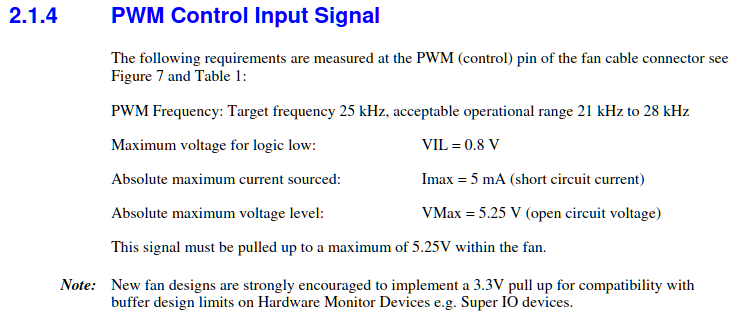
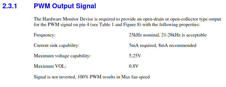
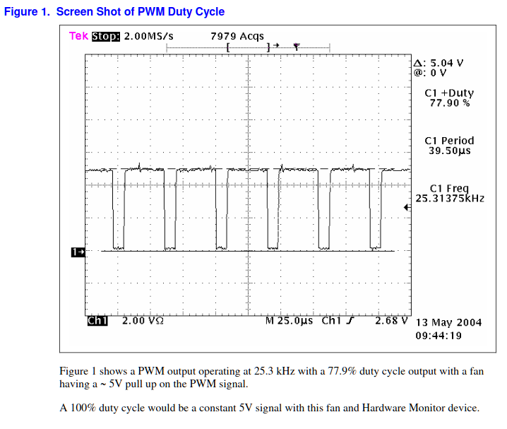
If they are normal 4-wire PC fans, they will be ~25kHz.

Indeed, PWM in general can be all over the place, but its use in PC's is defined by the intel 4-wire pwm fan spec is more narrowly defined in the range of 21-28 khz.

1676479109117.png


1676479124692.png


1676479173925.png
 
Back
Top