Project Open Core: Liquid P5, Hardline Tubing, Illuminated System Panel, VR Ready

Mr_Armageddon

Limp Gawd
Joined
Jun 3, 2009
Messages
252
Project Open Core: Thermaltake P5 Build (Introduction)

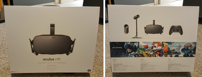
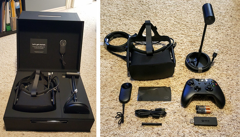
I have been using my current build for almost 5 years now, and it is time for an upgrade! Not only are the components getting a bit long in the tooth, but I recently received my Oculus Rift VR Headset, and my system just wasn't ready to help me step into the world of virtual reality.

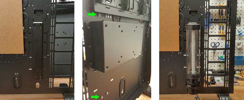
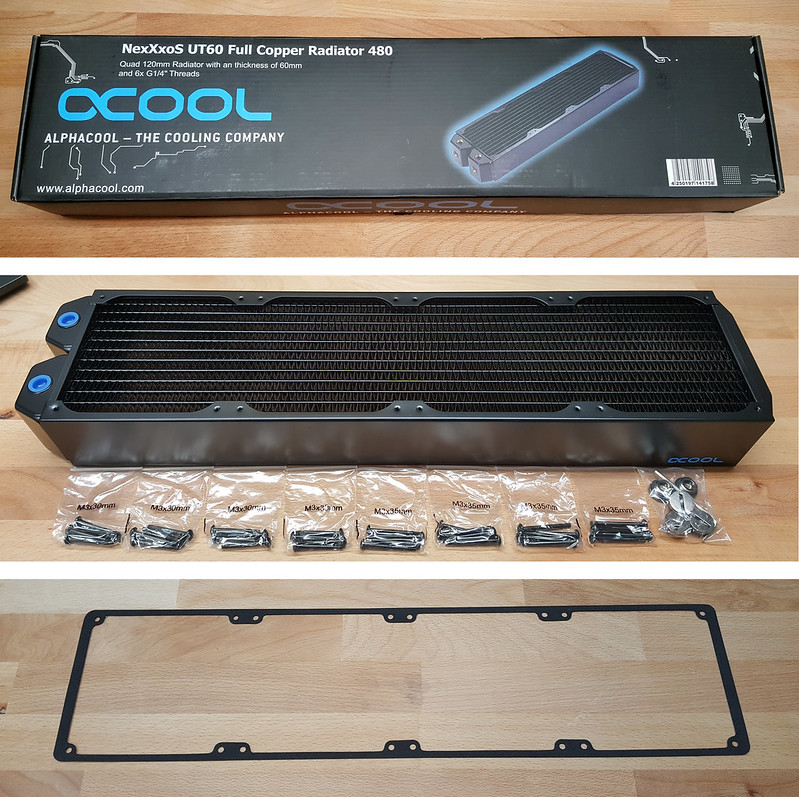
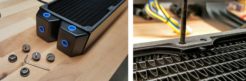
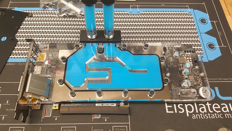
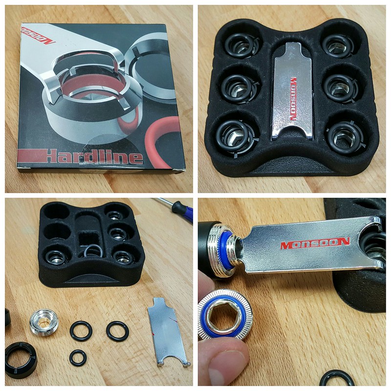
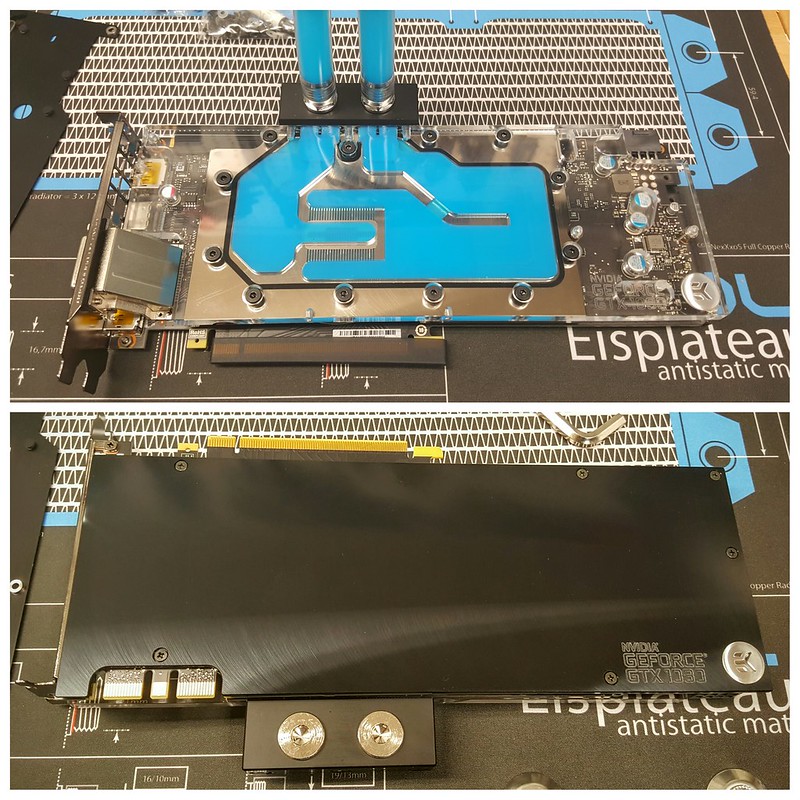
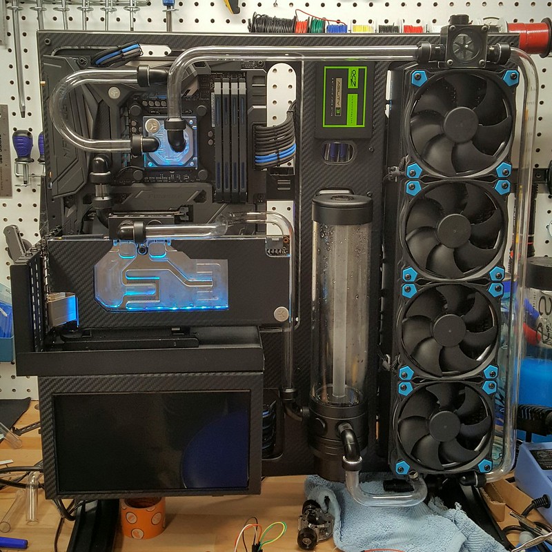
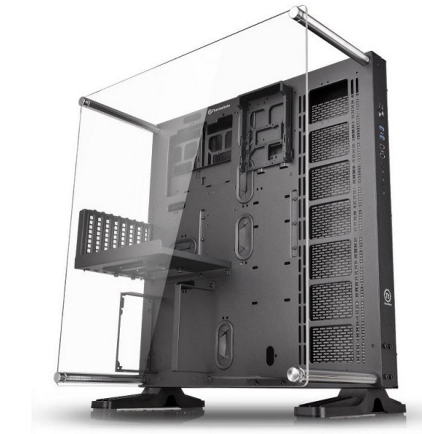
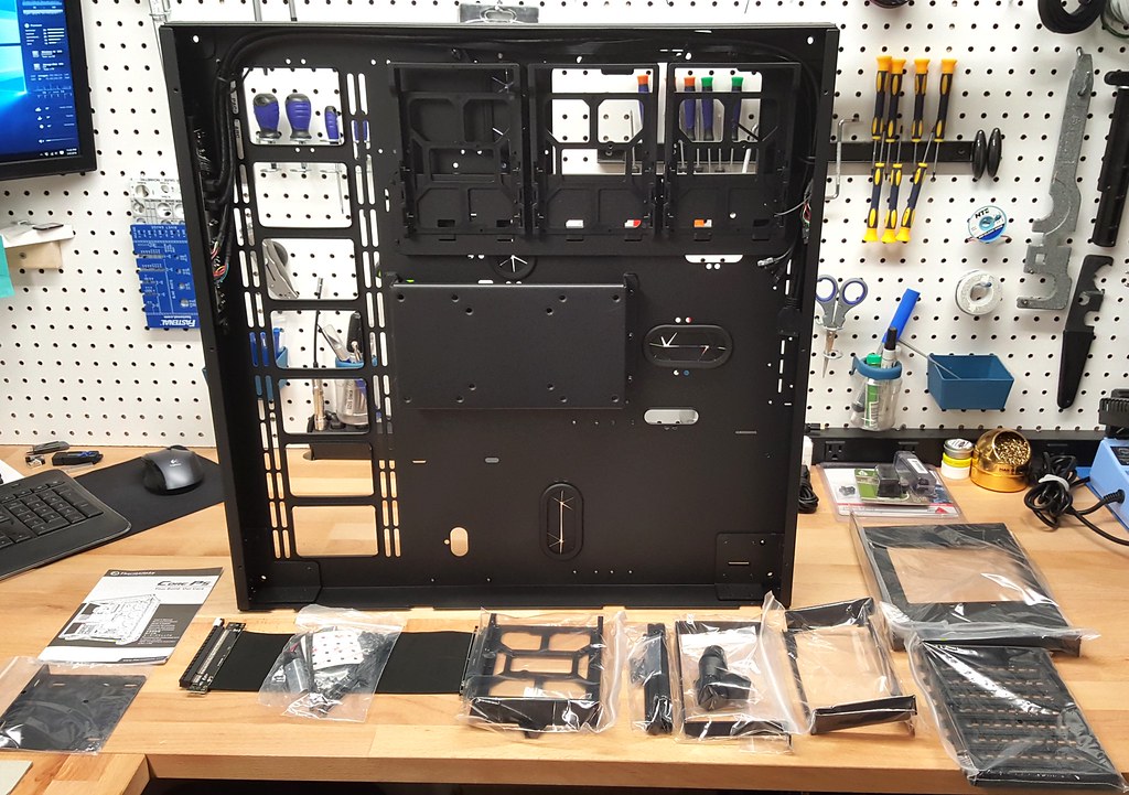
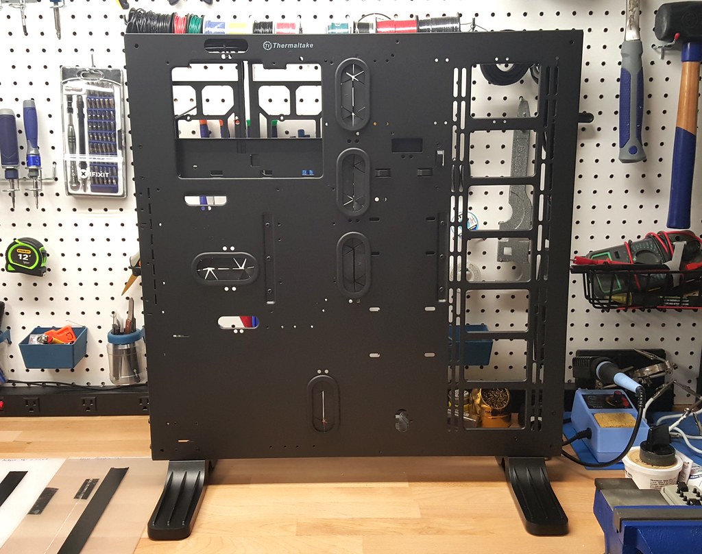
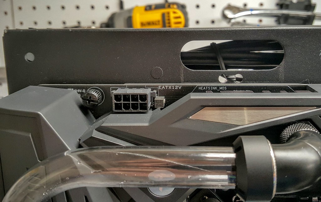
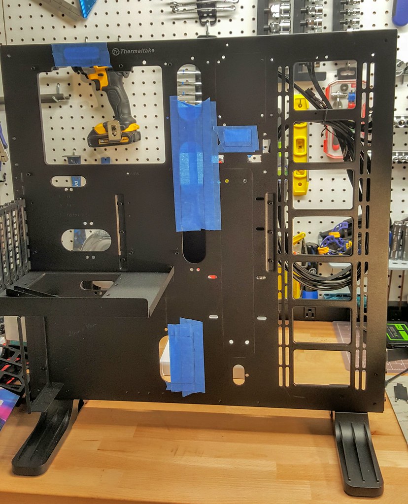
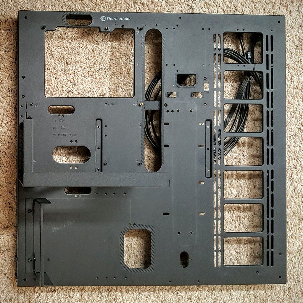
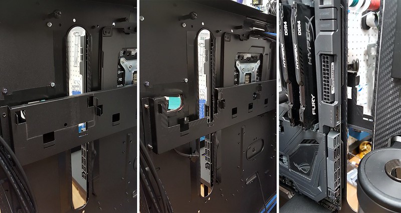
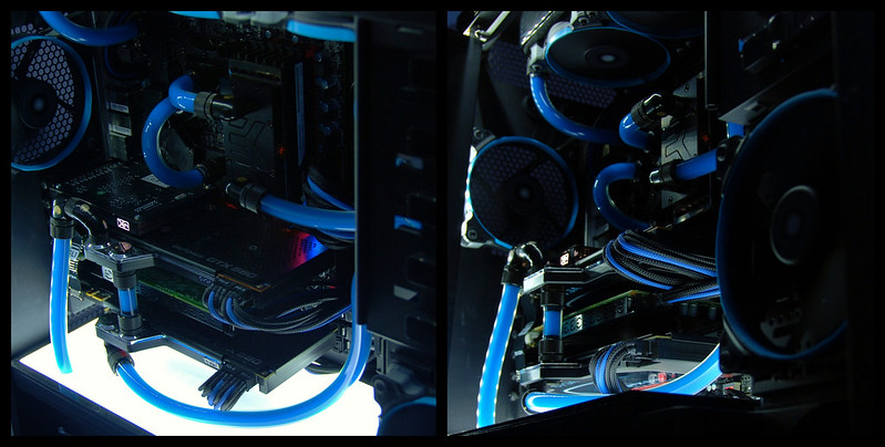
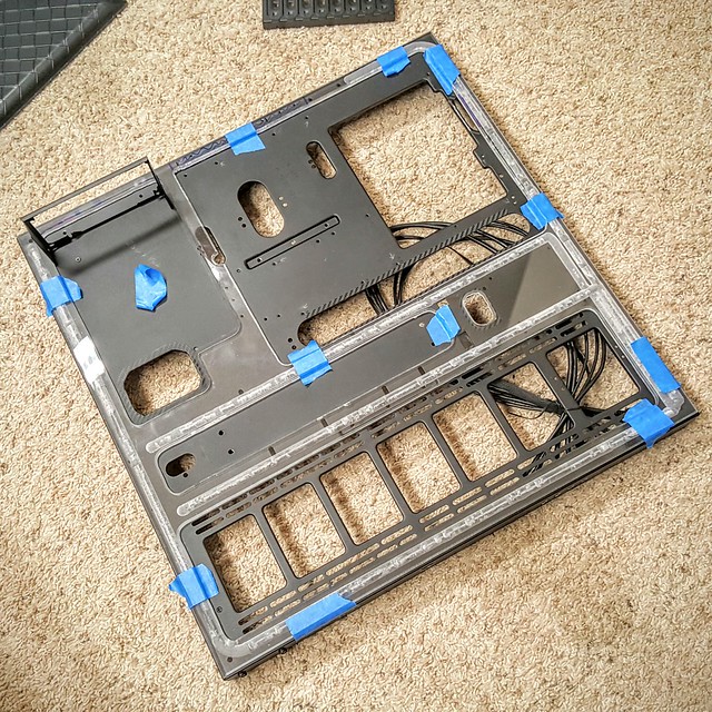
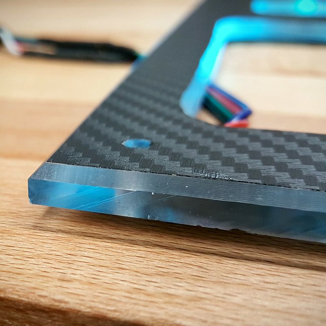
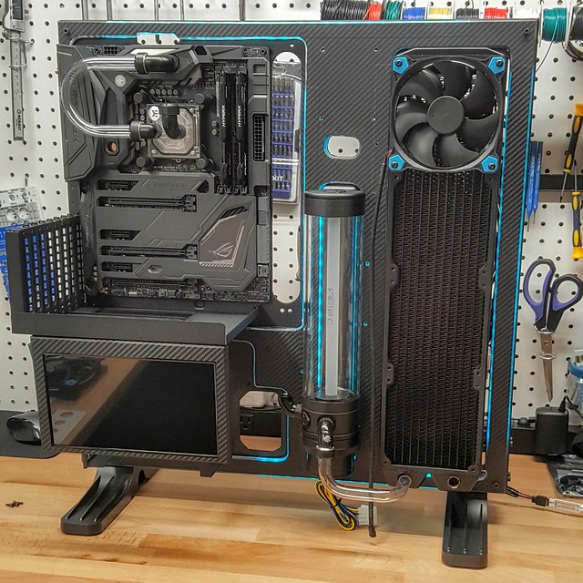
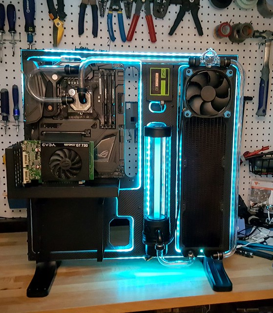
For this new build, will be using the Thermaltake Core P5, open air case. This time around decided to go with hard acrylic tubing, so I did a 3D render in Google SketchUp to get a better idea of how things would be installed, and what kind of bends I will need to do.


25948799540_e9af45c2e9_b.jpg

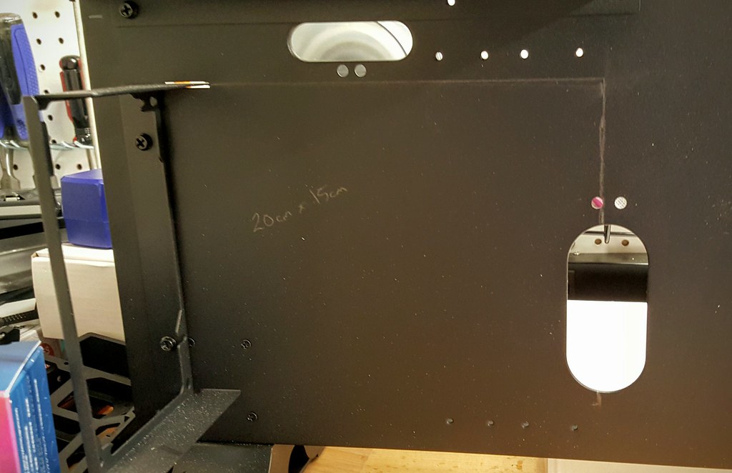
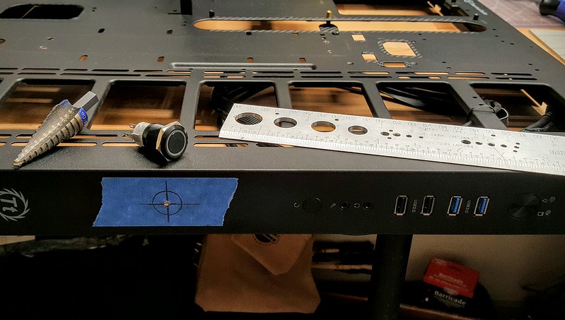
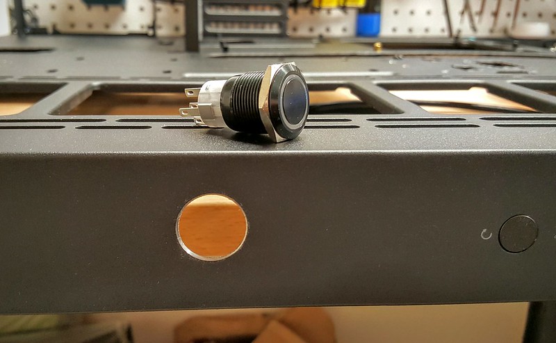
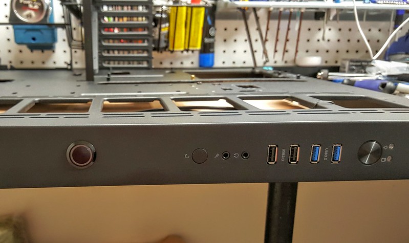
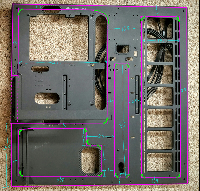
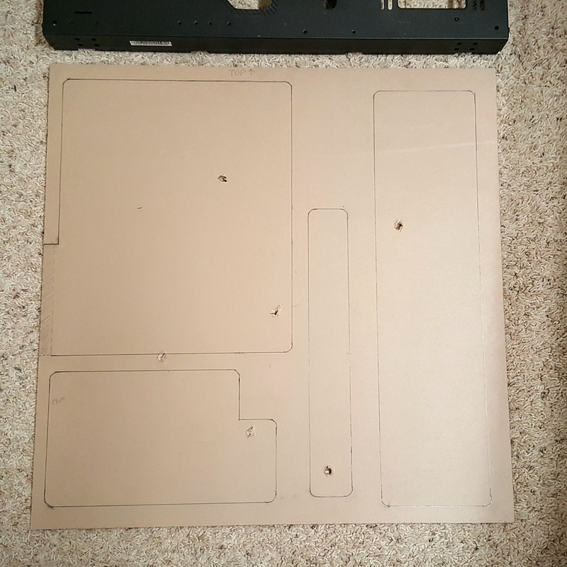
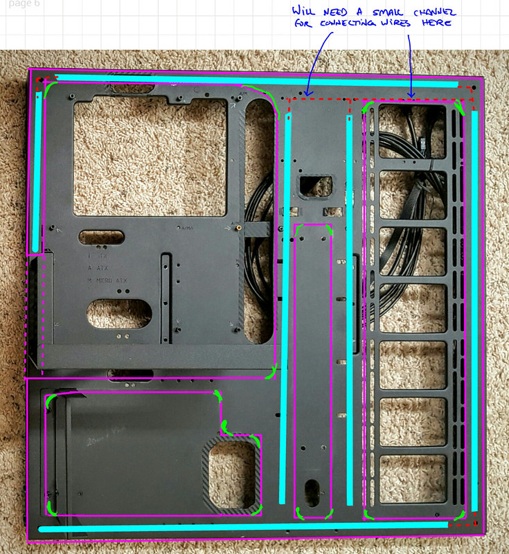
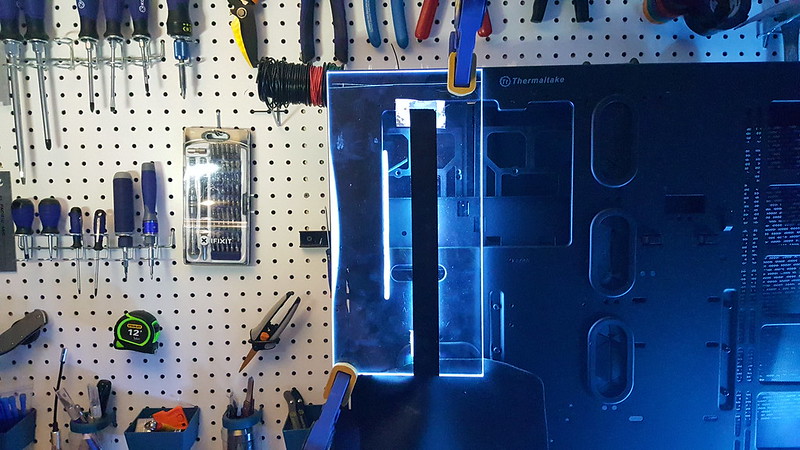
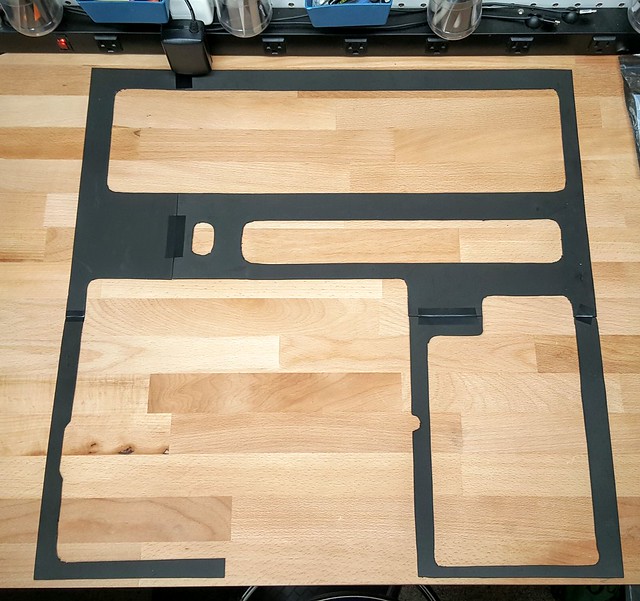
This is going to be a bit different from by previous builds using the Corsair 800D, as there will not be much "modding" required to the case itself (we will see if that holds true). I really like the design of the Core P5, and am looking forward to seeing what I can create using it.

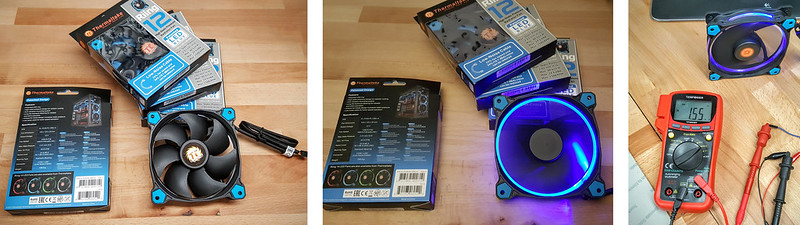
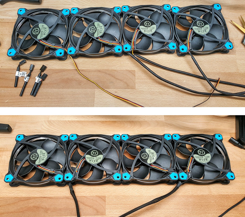
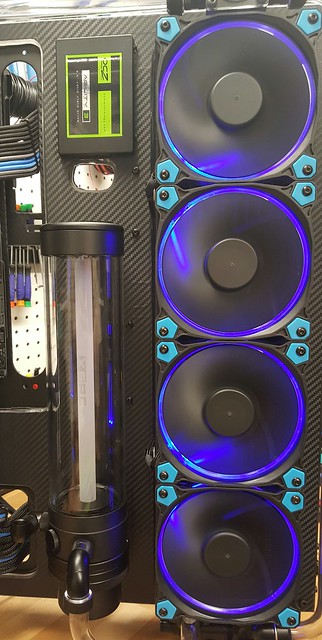
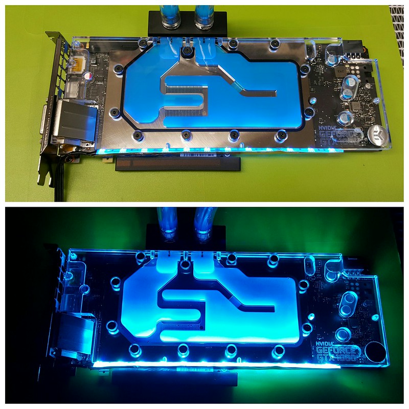
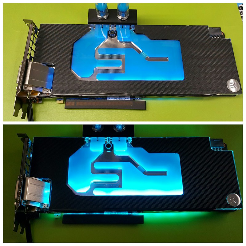
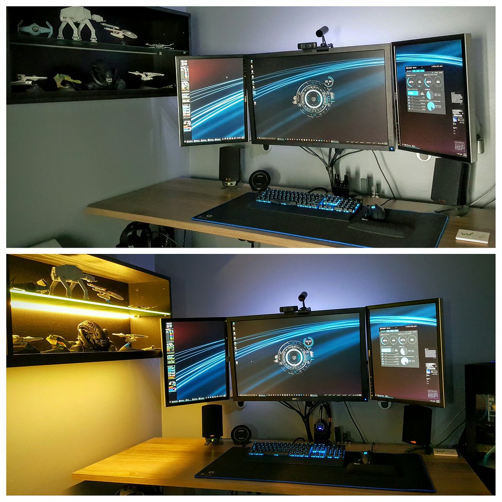
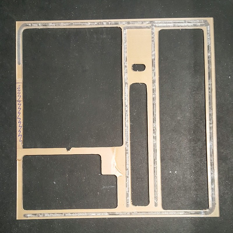
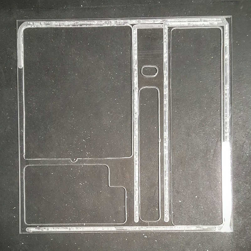
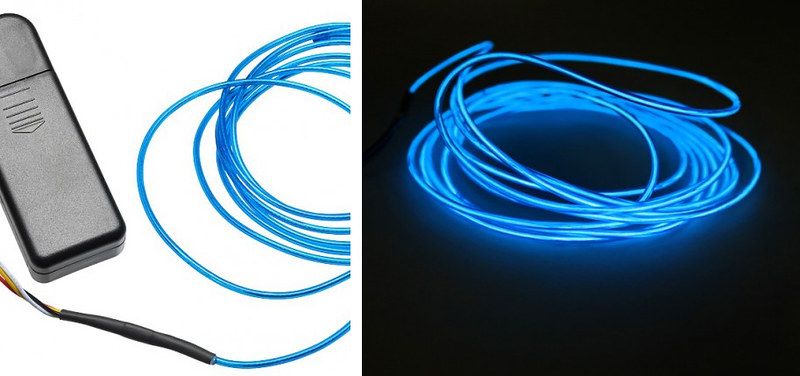
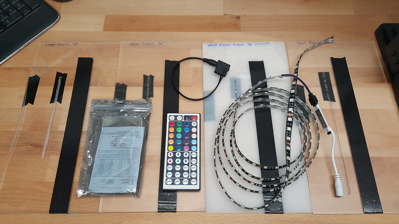
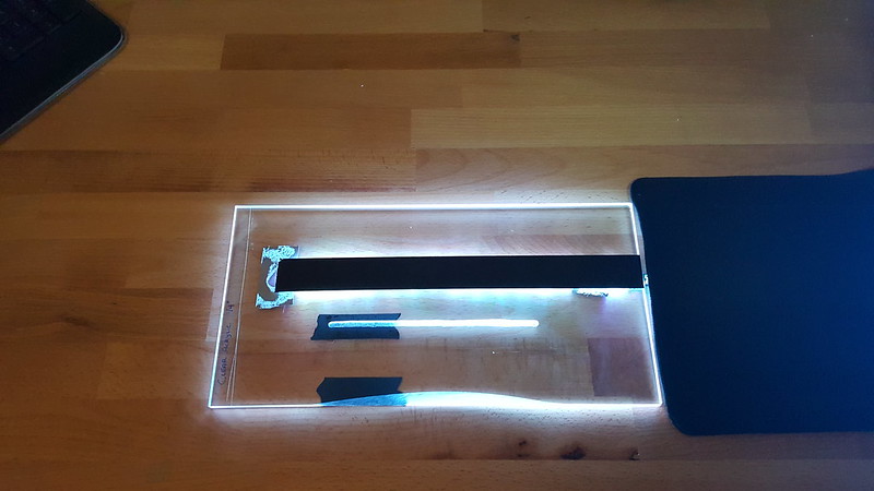
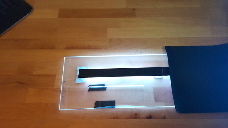
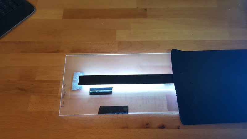
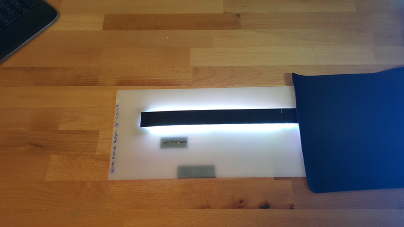
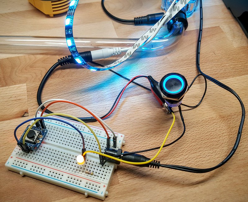
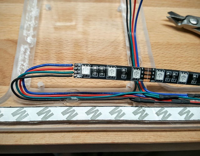
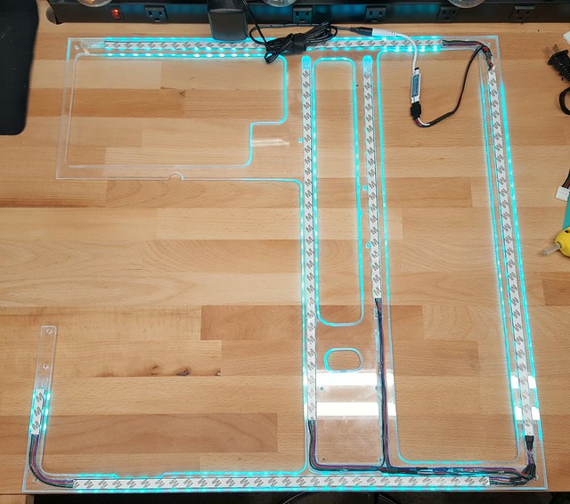
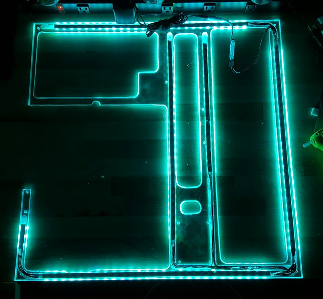
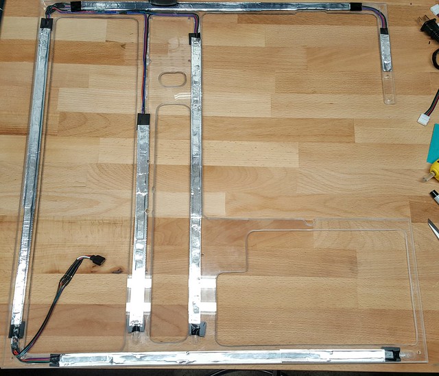
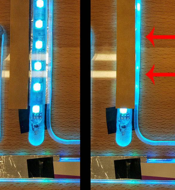
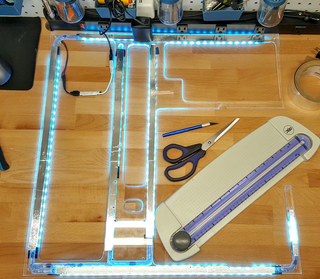
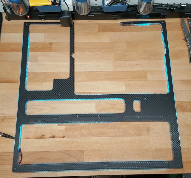
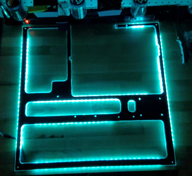
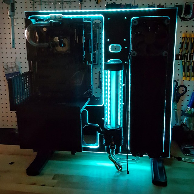
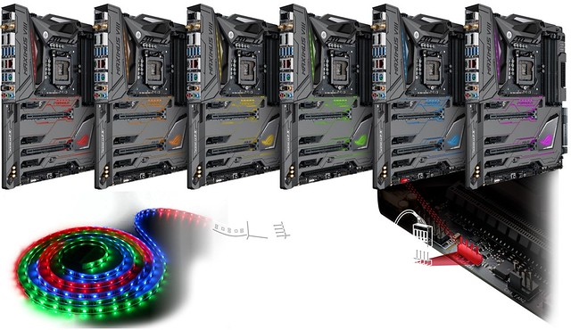
I will be including some custom lighting as well, but still deciding which direction I want to go with the acrylic panels, and lighting source. Testing both RGB LED light strips and EL Wire at the moment.

I will go into more detail regarding the components that will be used in a future post. Until then, check out this short video showing the 3D render from a few different angles.

Project Open Core - Thermaltake P5 Build (SketchUp Render)


8h7s8kl-jpg.jpg
 
Last edited:
Project Open Core: Build Components

I am simplifying the liquid cooling loops compared to my last two builds, as I am no longer going to be running SLI. With a single GPU (GTX 1080) I will be using 1 loop to cool the CPU, Motherboard, and GPU.

Here is the Component List:

  • Case: Thermaltake Core P5 Open Air Case
  • Power Supply: Corsair AX1200
  • Motherboard: ASUS ROG MAXIMUS VIII Formula
  • Motherboard Block: EK Integrated Crosschill MOSFET cooler
  • CPU: Intel i7 6700K
  • CPU Block: EK-Supremacy EVO Nickel
  • RAM: 32GB Corsair Dominator DDR4 @ 3200MHz w/ Light Kits
  • GPU: EVGA GTX 1080 (SC, SSC, FTW… waiting for release to know for sure)
  • GPU Block: EK 1080 Acrylic + Nikle (not yet released)
  • Sound Card: SupremeFX 2015 (On-board)
  • Hard Drive 1: Samsung Pro 950 256GB M.2 PCIe SSD (Operating System & Programs)
  • Hard Drive 2: Samsung Evo 1TB SSD (Games & Steam Installs)
  • Hard Drive 3: Seagate 2TB HDD (User Files)
  • Hard Drive 4: Seagate 4TB HDD (Storage)
  • Optical Drive: Samsung Blu-Ray / DVD+R (External USB)
  • Pump & Reservoir: XSPC D5 Photon 270 Reservoir & Pump Combo
  • Radiator: Alphacool NexXxoS 480
  • Coolant: Mayhems Pastel Blue Concentrate + Distilled Water
  • Tubing: Monsoon Hardline PETG Tubing 1/2" ID, 5/8" OD
  • Bending & Cutting: Monsoon Hardline Cutting & Bending Kit, Barrows Bending Tool
  • Fittings: Barrows Matte Black... and lots of them
  • Case Lighting: LED Strip 8ft 5050 RGB + 44 Key Remote
  • Acrylic Panel: 24in x 24in x 0.25in clear
  • Sleeving Material: MDPC-X (MurderMods) Sleeving Kit; Black, Blue, Heatshrink
  • Fans: Thermaltake Riing 120mm Blue LED Fans (x4)
  • Fan Controller: Phobya 4Pin PWM to 4x 4Pin Fan Splitter, ASUS AI Suite Software

This may change a bit as I get going, but for now it's pretty solid as I have most all the parts except for the GPU and accompanying block which haven’t been released yet.
 
Last edited:
Project Open Core: My Workspace

Recently moved into a new home, and there was a weird “closet” that is attached to the room that was to be converted into my home office. My wife had the idea to turn it into my project room, and it has worked out really well so far. Aside from PC modding, I also use it as a firearm cleaning station, and a place to work on my Quadcopter Drones / RC Cars. This picture also serves as my digital vault. If any tool goes missing, I can reference this photo as a reminder of where it goes... after I track down whomever "borrowed" my tool.

26958557550_d89b1e0943_b.jpg
Full Size Image Link​


My garage will also serve as a “workspace” for the messing cutting and routing parts of the build, but its just a normal garage and doesn’t merit any photo uploads.
.
 
Project Open Core: Case Mods

I have been wanting to start a new build for a while now, but none of the cases available were really what I was looking for. I had also been toying with the idea of doing a “Computer Desk” build for a while, but something always stopped me from going down that path. With the release of the Thermaltake Core P5, I found something that had a unique look, and the open nature of the case allows for so many custom options.

27186278501_b58587681f_b.jpg


It's a very large case, about the same dimensions of the Corsair 800D I am currently using. It also has the option to be wall mounted, but I’m not comfortable doing that with the added weight of a liquid cooling loop. It might work fine, but not a risk I am willing to take. I also feel the case is the best I have seen for displaying the beauty of a well set up liquid cooling loop. The fact that you can also install a GPU vertically is a big plus. I nice looking GPU Block is great but with most systems, you can’t really see it, and I am glad the Core P5 has addressed this.

27221935236_7df9963338_b.jpg


26649027144_6a7a92298a_b.jpg


As far as modding goes, I originally thought there wouldn't be much need to do much….
Turns out I was wrong. For most, it probably doesn't need any modding, but for what I am looking to do, it was time to bust out the Dremel Tool.

26650165433_80b1d5a039_b.jpg


There are various cut-outs around the case for cable routing, and they are not few in number. I was glad to see this, but I quickly found out that a few of the cut-outs don’t line up will with my hardware, and would have to be altered. First up, is the location where you can mount an SSD to the front panel. The existing hole is a bit too tight for my liking to route a SATA cable, so it needed to be enlarged.

26650163753_9d9781ee25_b.jpg


Next up is the power supply. I am using a Corsair AX1200, and it seems to be a bit longer than average. Because of this, the PSU would cover up about half of the cut-out, which would make it difficult to bring sleeved cables through. Needed to increase the size here as well.

26650163753_9d9781ee25_b.jpg


The cut-out at the top of the case to route the 8pin CPU Cable had to be altered because of the acrylic light panel I was building.

26650161933_9895c6a444_b.jpg


Also had to increase the size of the cut-outs along the Motherboard to have clean bends with my sleeved cables. This may not be an issue with other MoBos, but the 24pin location on the ASUS Maximus VII Formula didn’t line up well with the existing cut-outs. It would have still worked, but to get the look I was going for, needed to be altered.

27186145041_6772faa1a9_b.jpg


The cutting went well, and I will now have a bit more freedom to route cables specifically the way I want. Structural integrity of the case seems to be fine, but as mentioned before, no wall mounting for this build. Then went ahead and filed down the cut edges to be smooth, and as a precautionary measure, also wrapped all cut edges with a carbon fiber patterned adhesive vinyl.

27186143371_26c370a995_b.jpg


For High Resolution versions of all photos from this build log, please check out the Album on Flickr.
 
Project Open Core: Case Mods continued…

Ended up making 1 additional cut along the HDD support bar. Reason was again to provide easier routing of 24pin sleeved cable.

27158576222_201bac4961_c.jpg


Even though the ASUS MoBo can control the system lighting, I wanted a push button switch to turn the lighting effects on and off. Will be using a 22mm Blue Illuminated Vandal Resistant "Latching" Switch for this purpose.

26650157723_8d6113374e_c.jpg


Used a Step Drill Bit to make the hole.

26649012564_b6e0101984_c.jpg


It seems to have slipped a bit and its not perfectly centered, but not much I can do now, and it still looks fine.

26650164853_493b03f0a7_c.jpg


Next up, custom lighting and acrylic testing!


For High Resolution versions of all photos from this build log, pleas check out the Album on Flickr.
zaneross82
 
Project Open Core: Acrylic Light Panel - Cutting

As mentioned earlier, one of the custom aspects of this build will be a light emitting Acrylic panel that encompasses the entire front panel of the case, with cut-outs for the components to sit inside. The idea is the panel will “glow” around the components as well as the outline of the case itself. I went through a lot of testing to figure out what kind of acrylic panel to utilize for this feature along with different lighting sources, and will cover that in a future post. For now, going to show what I did to shape the panel for this build, in preparation for adding the lighting.

Below are the measurements I used to plan out where the cuts would be in relation to the components and existing cut-outs in the case.

26990903980_1e47dbf0ba_c.jpg


Starting off here is the Panel. It is 0.25in thick Clear Acrylic, and the dimensions are 24in x 24in to fit this case. I entertained the idea of using the acrylic that came with the case, but it seemed more ridged and brittle, so decided against it, and picked up this one for under $20 at a local plastics shop. I went ahead and outlined where the primary cuts will be, based om the location of the components.

26990902820_519ee8269b_c.jpg


I will be fashioning a jigsaw cutting table and picked up these blades to help. They are specifically made for plexiglass, and have less risk of chipping or cracks when cutting. Starter holes were drilled into the panel before cutting with the jigsaw.

27266430175_35669f6df3_c.jpg


Here is the cutting table. Pretty simple, just bolted the jigsaw underneath, with the blade poking through just enough to cut the acrylic. I used ripsaw guide clamps to try and maintain straight cuts, but even with those in place it was still difficult keeping those lines were they should be.

26990902700_2f7933eeea_c.jpg


27266427915_ecc8614932_c.jpg


26990902500_183c9e9a0e_c.jpg


The cutting went well overall, but as mentioned before, had some challenges with straight lines. Will definitely have to do some Filing cleanup work to make the appearance acceptable. Was a little worried when cutting around the areas that thinned out, but turned out to be pretty easy to manage those cuts which was a welcome surprise.

27266427625_2504640447_c.jpg


Here is what the panel looks like when applied to the case. The larger cut-outs will be for the Motherboard, Radiator, Power Supply, and Reservoir. Lots of cleanup work still needs to be done, but first on to cutting the channels out to male room for the LED strips.

26990902290_acd0ff81e3_c.jpg


For High Resolution versions of all photos from this build log, pleas check out the Album on Flickr.
zaneross82
 
Pictures just leaked of the EVGA GTX 1080 FTW Edition. Really liking the fact that it has 8+8pin power. Hopefully a slight OC as well. As long as EK makes a Waterblock for this version, I will be picking one up as soon as possible.


27201290881_1887d9aaf2_c.jpg
 
Project Open Core: Acrylic Light Panel - Cutting continued…

In order to get the light transmission I'm looking for from the LED light strips that will be used, the strips need to be set inside the acrylic. This will also allow for a flush install of the panel on the front surface of the case. I decided to use a router for this purpose, with a rounded bit to carve a “U” shaped channel that matches the shape of the light strip.

Here is the concept I drew up on my tablet of where the light strips will be located.

26990903180_91604020ff_c.jpg


Picture showing the lines that will guide my routing efforts.

https://c1.staticflickr.com/8/7081/26990902160_2eb4c65bc4_c.jpg

Here is the platform where it will happen. Similar concept to the cutting table, and qorkwd really well for the intended purpose.

27266426775_2c0136ea6d_c.jpg


Quick peek of the routing bit. The router itself was attached to the table using bolts that were countersunk as to not interfere with the panel while it moves along the surface.

26990901300_f06bff4ffd_c.jpg


Here is the aftermath of cutting / carving out the U channels. It went well and there were no issues. I considered using my Dremel tool to smooth out the channels afterwards, but found out that doing so actually affects the light diffusion in a negative manner, so left them as is.

27169364832_7d62e9dcf7_c.jpg


Removed the protective cover and now ready to do a bit more clean up before adding the lights. The channels that were cut are not only for the light strips, but also for the wires that will connect the various runs.

27266428645_8d3d57ea77_c.jpg


For High Resolution versions of all photos from this build log, pleas check out the Album on Flickr.
zaneross82
 
Project Open Core: LED Lighting & Acrylic Testing

I was pretty sure that going with an RGB LED strip was the way to go for this build, until someone introduced me to EL Wire. In concept is seemed like a great fit as long as you got the right color as you cannot change it on the fly like you can with RGB LEDs.

So I purchased some Blue EL Wire to try it out. It would have worked great in regards to the install, as it is much smaller than the LED strip, and would easily bend around the curves in my acrylic panel. The brightness level was pretty low, but that was fine as I just wanted a subtle glow and not glaring lights. The problem was the whine… a high pitched, very annoying electrical whine. I even purchased a different transformer hoping it would fix the problem. It was a tad quieter, but still not something I could have going next to me a few hours a day. So threw out the idea of using EL Wire.

27037021160_38c7ef9ec8_c.jpg


Aside from the electronic whine, the decision to go with the LED strip was also driven by the fact that the ASUS ROG Maximus VIII Formula has an RGB header allowing my to sync an RGB LED strip to the other colors emitted from the Motherboard. That kind of customization cannot be achieved with EL wire, so I went with a 6ft RGB LED kit that included a 44 button IR Remote and 4pin MOLEX to a 12V barrel plug adapter. The back of the strips are adhesive as well. I played around with the different color options, and the flexibility of this kit is excellent.

26705076874_c89877b9e8_c.jpg


Now to rewind time a bit. Before I started cutting my acrylic panel, I and to decide which type to go with. When deciding on which type of acrylic panel to use, I tested the following plastic samples:

  • 1/4in Clear
  • 1/4in Frosted
  • 1/8in Clear
  • 1/4in White

I cut a “U” channel into each piece and also shaved a beveled edge on on side. Placed the LED strip behind the panel and fired up the lights to see which gave off the right amount of light around the edges.

First up is the 1/4in Clear. Since you have already seen the larger version, you know this one was the winner. It had just the right amount of light transmission along the edges, and was thick enough for me to shave a 45 degree bevel so the light around the edges shines up and not just out.

27279002186_f719b4e646_c.jpg


This is the 1/4in Frosted sample. It was ok, but diluted the light a bit too much around the edges.

27037019940_99fa7a4fab_c.jpg


Same as above but 1/8in this. Found this to be too thin for me to use at all.

27037018940_af2fe0a1f0_c.jpg


Last up was the 1/4in White sample. I actually thought this would work really well, as I have used they type in my last build, and it did really well.

27037018090_fc119bf3c8_c.jpg


The difference is that in the last build, the objective was for the light to shine up through the panel, and not out around the edges. Turns out the white panel doesn’t do the edge glow well at all.

7898425948_0639f8e0cb_c.jpg


So with the winner selected, I purchased a 24in x 24in panel, and got to work as shown in the previous posts. Here is a picture of the sample that I was playing with to make sure it would give me the desired glow.

27037017360_b66cb66545_c.jpg


I also had to make sure to get the wiring correct for the latching vandal switch that will be used to turn on and off the LED strip. The switches I used in a previous build couldn't take a direct 12v current. So I tested this one using a breadboard with a resistor so I wouldn't accidentally burn it out. After a bit more research, this one in particular can in fact take a direct 12v load, so no need for the resistor, and it will be wired into the case after I install the LED light strip.

27037016490_3ae0ced218_c.jpg


For High Resolution versions of all photos from this build log, pleas check out the Album on Flickr.
zaneross82
 
Project Open Core: New Addition to Workspace

Quick post regarding a Workspace upgrade. I have an antistatic mat that I have been using for the last 15 years. It works fine, but a bit small, and very ugly. Came across the AplhaCool Eisplateau Antistatic Mat, and knew that it needed to replace what I currently have.

27281706822_f5cd6e94b3_z.jpg


As can be seen in the picture above, not only does it look great and do everything an antistatic mat should, but also has a ruker in CM and Inches, Scale sizing of Radiators, Fans, Tubing, pumps, etc. Even has pin layout diagrams for your PSU cables and Vandal Switches.

27379561625_0b2be0ca7c_z.jpg


Here is the mat on my workbench. I may have underestimated the size. It just barely fits on the surface.

27281666402_1fec2506ec_z.jpg


This picture should give you an idea of how large it is (120cm wide x 60cm deep) near the also large Core P5 case.

27379559035_0564817b17_z.jpg


Very happy with this upgrade to the workspace, and hope to get as many years out of this mat, as I did my last one. Now on to installing the LED light strips!
 
Project Open Core: Illuminated Panel - Wiring & Install

Now that the panel is prepped, time to add the lights! Before doing that, I had to do one last check to make sure everything was lining up properly, and verify that I had accounted for any mounting / screw holes before starting to lay wires.

27092801850_37d41cdd85_z.jpg


I had initially purchased some a few 10in RGB LED connector wires to make it easy for me to run the various “tracks” of lighting. These ended up being too stiff and rigid, and the connectors were very thick, so went with the old standby of soldering every wire. I had to add these wires because the LED light strips were not pliable enough be make the bends around the corners of the channels I had cut out.

27334909976_1088e0f34d_z.jpg


In addition to soldering the 4 required wires to each segment of LED strip, I also used hot glue in a few places to keep everything where it should be. Below you can see all the strips have been applied, and the lights have been turned on to test.

27092802660_cd6175b92b_z.jpg


Same test as above from the back of the panel, but with the lights off. Note that this is not the final color that I plan on using. It looks cool, and has a nice “TRON” theme going on, but will probably go for a more Royal Blue when done.

26760644104_f1c7209a63_z.jpg


In an attempt to get as much light as possible to shine through the sides, I put reflective duct tape behind the light strips. It did help a bit, but applying it to the front had a much more noticeable effect.

27092802520_c536131450_z.jpg


Here is the reflective duct tape being applied to the front of the acrylic panel, on top of the LEDs. You can see in the side by side example below, I get a much more even light through the sides when the reflective tape is applied.

27092802800_aa82db5d56_z.jpg


View from the front with the reflective tape applied.

27093050250_5365682e23_z.jpg


For High Resolution versions of all photos from this build log, pleas check out the Album on Flickr.
zaneross82
.
.
 
Illuminated Panel - Wiring & Install continued...

After verifying the light diffusion was about what I wanted for the panel, I went ahead and applied the Carbon Fibre Vinyl to the top of the acrylic panel. Not only does this ensure the light is only emitted through the sides of the panel, but it also cleans the look of the panel up, and covers all of the extra holes and cut-outs that are spread around the surface of the P5.

27093050150_3f8003144e_z.jpg


Same as above, but with the lights off. You can see the screw holes in the panel, but once everything is put together, the only light showing will be along the edges of the panel.

26761741173_d3e5995c06_z.jpg


I explained in a previous post that I used and router to shaved a beveled edge on the top half of every side and cut-out. The goal was to allow for the light to shine up towards the components and not just out the sides. Here is a nice close up of what the edges look like.

27334909446_4a53474e35_z.jpg


Made a quick “gasket” out of 2mm black foam that will go between the acrylic panel and the case. I was worried about cracking when applying pressure to the screws, and couldn’t really use rubber washers as it might make the light diffusion look uneven. Even it that wouldn’t really happen, it was pretty simple to make this gasket, so I went ahead and did it.

27092802130_5ffa1dbfa4_z.jpg


Now we have the panel installed, and did a test run of the lights with the primary components installed to get a better look at how it will shine around them. The pictures below are taken at 3 different lighting levels. Really liking the way this is starting to look. Not going for the “TRON” look, but kind of diggin’ it now...

26761740843_582775d0df_z.jpg


26760643574_7d3c11bcc6_z.jpg


I have a feeling the reservoir is going to look awesome once filled with some pastel blue liquid with that LED shine behind it.

27270526792_50b59c74a1_z.jpg


Next up, going to go over the hardware that will make up the rest of the build, and any modifications I have to do to make things look the way I want them to.


For High Resolution versions of all photos from this build log, pleas check out the Album on Flickr.
zaneross82
.
.
 
Project Open Core: Hardware - Motherboard, M.2 SSD

I have been using an EVGA X58 Classified with an Intel i7-970 in my primary build for the last 5 years. The six core i7-970 still handles games and video editing without issue. It's been a great combo, and I considered using them again being that performance wise, they still hold up very well. At the end of the day, I decided 5 years is just too long to go on my primary system without an upgrade, and there were some new Motherboards out supporting a few features that I really wanted to leverage.

Enter the ASUS MAXIMUS ROG Formula VIII

27419914835_8cb72dc046_z.jpg


I have always appreciated the features and quality of the ASUS ROG line of products, but wasn’t a fan of the RED themed hardware. Was very pleased to learn this new Motherboard had a muted black / gray look along with RGB LEDs so users could customize the look to match their system theme.

26812830973_99e3a217d2_z.jpg


This MoBo has tons of bells & whistles, but it sufficeth to say that it looks great, and performs even better. A few of the key things I was also wanting in a motherboard besides what I just listed was built in Wireless N, USB 3.1 C support, and good on-board audio. The Formula VIII has all that and more.

26812831023_89619573e3_z.jpg


There are plenty of reviews out there that list all the cool things about this board. I am going to focus mostly on the aesthetics and how they will play into the theme of this build.

27419913785_65a0fe0a9a_z.jpg


From the front we see the matte black / gray coloring in everything from the “Armor” plating to the PCIe and RAM slots. Another thing that is pretty obvious, and one of the many reasons I went with this board, is the built in waterblock (made by EK) for the MOSFETs.

26812831583_c1d20b8daa_z.jpg


The software that comes with the board can not only control the RGB LEDs on the board itself, but also an RGB LED light strip via a 4-pin header. This was really important for this build as it will allow me to easily sync up the colors on the motherboard and light strips behind the acrylic panel.

27151989970_ebeef2c687_z.jpg


Here is an exploded view showcasing the “ROG Armor”. ASUS claims that not only does it physically protect the board, but via thermal pads, it also pulls heat away from critical components. If it does all of that, great… as long as it does it while looking really good in the process.

27357614431_06cdc5c365_z.jpg


For High Resolution versions of all photos from this build log, pleas check out the Album on Flickr.
zaneross82
.
.
 
Project Open Core: Hardware - Motherboard, M.2 SSD continued...

Behind the ASUS ROG logo (which also lights up) is where the M.2 SSD is housed. I have been using this storage medium for about a year in my laptop, but have never owned a desktop that supported it. They were smart with this version of the MoBo as this panel can be removed and the M.2 drive changed out without having to remove GPUs, which would be a real pain if using a traditional liquid cooling setup.

26812830493_dc31c64e36_z.jpg


To be installed in this spot and drive my OS and Programs, I will be using the Samsung 950 Pro M.2 SSD. I considered going 512GB, but since all of my media and game installs are on other HDDs and SSDs, and my current OS / Programs is only using about 40% of the 256GB capacity, didn’t spring for a larger size.

27419907065_accc342a82_z.jpg


Really amazing how small these things are. Here is a quick comparison against a USB mouse receiver.

27419905965_5499a2e09f_z.jpg


And here we have it installed in the motherboard. Once the place it put back on, you won’t see any trace of the M.2 SSD, but I am pretty confident it will be quite noticeable performance wise once everything is up and running.
26812827273_f1a5a144a7_z.jpg


For High Resolution versions of all photos from this build log, pleas check out the Album on Flickr.
zaneross82
.
.
 
Currently one wicked looking build. I will be keeping an eye on this one! Very well done.
 
Project Open Core: Hardware - Oculus Rift

I was planning on posting some of the modifications I am planning with my RAM and CPU Block, but had to catch a plane for work before the RAM arrived, so going with some pictures I already had on hand.

One of the reasons that I decided it was time for a new rig, is that the system I had been using for the last 5 years, just wasn't ready for the VR experience. Although my CPU would theoretically work, my GPUs definitely would not, and I was lacking in USB 3.0 ports. This wasn't the sole reason that drove the upgrade, but it was a big part of the decision.

I am getting more into Space Flight Sims, and from what I have seen so far, the Rift is going to be amazing for that particular type of game.

27160098060_463688c1bc_c.jpg


Although I ordered within 5 minutes of the commercial launch, my shipment was delayed until late May. When the Rift finally arrived, I was pretty excited.

The packaging is really well done, with a look and feel of something very high end. I don't really see myself playing many games while wearing the Rift that would require a gampad, as I play Space Sims with a HOTAS flight controller, but willing to try it out with some other games since it comes with the package.
27160102670_c7038b216c_c.jpg


I have been dabbling in Virtual Reality for a bit now, as I picked up a Gear VR around Christmas to go with my Samsung Galaxy Note 5. Even for something limited to what phone hardware is capable of, I have really enjoyed playing games and watching movies on the Gear VR. Even more so, I love letting someone try it for the first time just to get their reactions. I have only sampled a few titles with the Oculus and the PCs greatly superior hardware, and so far have been very impressed. Looking forward to see what else comes out over the next year or two.

27402413656_abf314e71b_c.jpg


One thing I had trouble with when setting out the Oculus stuff, was the tracking camera. I have an adjustable Desk, and the camera kept hitting the bottom of my monitor, and took up too much desk space. My gaming headset was doing the same, so I set out looking for a solution. Here is what it looked like before, tracking camera directly below the monitor and the gaming headset to the left.

27337527172_73e5228898_z.jpg


I had read that the shaft holding the camera had a standard camera tripod thread. So I grabbed an adjustable hot shoe adapter from my DSLR bag, and picked up a monitor mount for the PlayStation Eye Camera online.

27436499235_7cd3306155_z.jpg


The end result works out pretty well. The Tracking camera now sits right next to my webcam, doesn't hit my monitor when I change the height of my desk, and uncluttered my desktop a bit. You will notice in the picture below, the headphones are also gone.

27337526302_738d889a1c_z.jpg


I needed a better place for the gaming headset, and somewhere to stash the Oculus Rift when not in use. Came across this headphone holder on Amazon, that looked perfect for the job. Made of a combination of hard plastic and aluminum, it is very solid. The lips on the end of each arm will also keep the Rift from accidentally sliding off.

27436496175_5bee164f73.jpg


It uses a 3M super sticky pad (same that ship with GoPro mounts) to secure to the bottom of my desk. I tested after placement, and I don't think it will go anywhere without taking a chunk of the desk with it. As seen below, it hold the gaming headset and Oculus Rift perfectly under the desk. Out of the way, but easily accessible.

27160100000_02c038c811_z.jpg


I am actually posting this from a plane, on my way back home. I know via a shipping notification that my RAM and Light Bar upgrade kits have arrived, so the next post will cover some simple mods I plan to make them match the Black / Blue theme of this build.


For High Resolution versions of all photos from this build log, pleas check out the Album on Flickr.
zaneross82
.
.
 
Arrived home from a week of work travel, then took my wife on a weekend getaway, so haven't had much time to update anything. Before I left, I did get a quick chance to play with some Plasti Dip and the Corsair Dominator Light Bars that arrived while I was gone. They already have Blue LED inserts, but the silver/grey of the bars didn't look right. So blacked them out with the Plasti Dip, to better match the theme of my build.

26869591704_5eca1131a2_c.jpg
 
Project Open Core: Hardware - CPU & Waterblock

For this build’s CPU, went with what seems to be the obvious choice nowadays, Intel i7-6700K. I'm not into super heavy Overclocking anymore, but will still go for a slight OC and probably settle at around 4.5GHz. Looking forward to see how the performance of this CPU stacks up against my current i7-970.

27253127560_3e1695ddbc_z.jpg


I had considered going with the X99 platform as an upgrade from my X58. But being that I'm not trying to achieve any crazy OC benchmark records, and the there weren't as many options that looked as good with the matte black and RGB LEDs, decided on the Z170 platform.

26921432533_1f706afa0b_z.jpg


For the CPU block, went with with an EK-Supremacy EVO Nickel. It's a really nice looking block, and performance is up there with the rest of the best brands (Swiftech, Heatkiller, etc).

27430778772_8efedd3423_z.jpg


27430778102_fab98aa986_z.jpg


One of the reasons I went with the acrylic top is I wanted to be able to see the fluid as it goes through the block. This one also has holes to insert LEDs. Not sure if I want blue or white behind the fluid, will have to experiment a bit with that one to see for sure. The same will then be applied to the reservoir, and GPU block.

27432805722_25b51410a0_z.jpg


One thing I didn’t like about the EK kit, was the chrome / shiny finish on the retention knobs. A little spray paint made for an easy fix to match the rest of the build.

26921434173_6e17778dc2_z.jpg


Block is now installed, and I have started experimenting a bit with some hardline bends. Have a good ways to go with that, and will be sure to share my progress in a future post.

27432984962_61141a18ab_z.jpg


For High Resolution versions of all photos from this build log, pleas check out the Album on Flickr.
zaneross82
.
.
 
Project Open Core: Hardware - RAM

My previous system had 12GB of DDR3 RAM. Initially I thought that would be plenty, but as I started working more from home, and having 3 separate browsers open plus any applications I was using, started to see my RAM usage hover around 90%. Making the jump to 16GB was a no brainer for this system, and I thought I would be fine with that. Decided to go with a kit of Corsair Dominator Platinum DDR4 @ 3200MHz. Was also planning on adding the light bars for the blue LED effect.

Then came Memorial day and it's accompanying sales. Not only did I have a promo code, but they also Corsair also had a promotion to get the light bars for free with the purchase of a Dominator RAM kit. At the end of the day I was able to upgrade to 32GB of RAM plus the light bars for an additional $30. Couldn’t pass on that deal.

26935512533_bc1ee86e02_c.jpg


The light bars are a nice touch to the Dominator kit, but I did a few modifications to make it better match my build theme. First I colored the sides and bottom of the acrylic “light transmission” pieces so they would glow blue instead of white. I left the tops alone, as the blue plastic inserts would do a good enough job by themselves.

27509680306_9ae732bac0_c.jpg


I then whipped out the Plasti Dip and changed the color of the bars themselves from Silver to Black. Last coat was Matte Black spray paint to get rid of any gloss. The end result looks great.

27509678676_a1eb63b320_c.jpg


26935512943_a3f25d8cc0_c.jpg


Here is the kit installed, and with the LEDs shining. I quickly turned on the MoBo just to get everything to light up. Will take better pictures once I get further into the build and get all my colors working together, but so far I am really liking how this mini-mod turned out.

27471923751_e2479c6f3f_c.jpg


For High Resolution versions of all photos from this build log, pleas check out the Album on Flickr.
zaneross82
.
.
 
Project Open Core: Hardware - System Status Display, USB 3.1 Card

I have wanted to add some sort of system status display to a build for a while now, and decided it was time to do it. I was initially going to place a small 4in display on the front of the case where you can mount an SSD, but decided to go bigger. Found a 7in HDMI display on fairly cheap on Amazon. Not very high resolution, and the screen quality is not great, but works well for the intended purpose, which is to run the CAM dashboard on it, looking something like this.

27473646581_7702eec9f8_c.jpg


Wasn’t a fan of the glossy finish, so wrapped it in Carbon Fibre vinyl. It also has a camera shoe mount which made attaching it to the case easy. I like this option as it allows the screen to swivel a bit, so I can point it towards me. The buttons are pressure sensitive, and aren't’ affected by the vinyl. I doubt I will actually use the buttons much, as it simply powers on with the system, and also comes with a remote for settings navigation.

27473646421_54fbd9f1e5_c.jpg


Here is a view from the sides to see the connectors. Requires a 12V power source and either HDMI or VGA (via a VGA to Mini USB adapter) to run the display.

26936375774_794479ed8c_c.jpg


Here is a picture from earlier in the build log, showing it mounted to the case just below the GPU support. I will get additional pictures of the software running on it once I get the system fully built.

26761740843_582775d0df_c.jpg


I also decided to add a PCIe USB 3.1 expansion card to the build. The ASUS ROG Maximus Formula VIII has a ton of USB 3.0 ports, and even 2x 3.1, one of which is the new Type C connector. Problem is, I have a lot of peripherals, and with the addition of the Oculus Rift, needed more ports. I have tried various USB 3.0 hubs, but have had issues when using them with the Rift, so going the direct route.

26936374614_552d2ceed1_c.jpg


The card is a PCIe x4, so I had to purchase a riser cable to mount it. It was already shielded, so I just wrapped it in the same Carbon Fibre vinyl to eliminate the reflection. In order to utilize the full current potential for USB 3.1, you have to attach a SATA power adapter as well.

26936373654_1ed26d3193_z.jpg


Install was pretty simple. It sits directly behind the GPU, and will be pretty much hidden from view. It is also very stable which was nice to see, as that was one of the concerns I had with the vertical GPU mounting method this case uses.

27473646041_49b667b4b3_c.jpg


For High Resolution versions of all photos from this build log, pleas check out the Album on Flickr.
zaneross82
.
.
 
Project Open Core: Hardware - Reservoir & Pump

In previous builds I had used reservoirs that fit inside the 5.25in bays on a PC tower. Being that this case has no optical drive spaces, decided to go with a traditional “tube” res for this build. Went with the XSPC D5 Photon 270 Reservoir & D5 Pump Combo. Really like the look of this Res, especially with its glass and aluminum construction.

27465478262_5e76a5d4fb_c.jpg


The pump comes with a mounting bracket, foam anti-vibration pads, and LED that can be inserted into the bottom of the rese to make the internal acrylic tube glow from within.

26955733063_d3b81b58f8_c.jpg


This particular variant of the D5 pump is the Variable speed type. Not sure what I will keep it at, but I am going to as little noise as possible while still getting good performance so probably around level 3.

27287500200_c57b592e0f_c.jpg


Here is a picture of what the glow tube looks like when an LED has been inserted. I like the look of it, but not sure if I will end up going with the White LED as shown below. My use a Blue LED, but need to test out which one looks better with the fluid that will be added to the system.

27287498860_39d9e33c0a_c.jpg


The fill port at the top of the Res is larger than a standard fitting to make filling easier. I also have an adapter to a standard G1/4 fitting size in case i want to use my fill funnel at some point.

27564337165_4ab1c45179_z.jpg


The only part of the Res / Pump combo that I didn’t find aesthetically pleasing, was the plastic ring that holds the pump to the res. It just doesn’t go with the high quality look the rest of the unit provides, but luckily XSPC provides and aluminum replacement ring to upgrade the look. Much better in my opinion.

27465475462_eedd798c53_c.jpg


The Core P5 didn’t have any mounting holes for this particular Res, so I had to drill a few holes, and secure them with the provided mounting hardware. Very easy to do, and once installed it looks great. Can’t wait to start filling this thing with some Mayehm’s Pastel Blue liquid!

27465476722_5603e09c53_c.jpg


For High Resolution versions of all photos from this build log, pleas check out the Album on Flickr.
zaneross82
.
.
 
Project Open Core: Hardware - Radiator & Fans

My previous build I had 2 separate radiators, one for each loop. A 360 for the CPU, MoBo, and RAM, and a 240 for the GPUs in Push/Pull configuration. I have a few less waterblocks this go around, and will not be running SLI, so I opted for a single Alphacool NexXxoS 480 Radiator. Look and feel is very nice, and the reviews I was able to find show that it performs really well.

Also picked up an inexpensive “gasket” to go between the rad and fans.

27484945002_724ebcb897_c.jpg


One thing I really like about this rad is that it has 6 inlets + 1 fill / bleed port at the top. Tons of configuration options with that layout. They also put a metal gaurd below the screw mounts so you don’t damage the radiator fins by going in too far. That is something my last set of radiators did not have, and is a nice addition.

Comes with everything you need to get started, including port plugs and various lengths of fan and mounting screws.

27484943942_30b5ffa09b_c.jpg


For the fans on this build, going with the Thermaltake Riing 120mm Blue LED Fans (x4). These ones are specifically made to work with with radiators (static pressure), and the blue LED accent around the fan is a nice touch. I saw at computex they just released an RGB version, but for now blue is fine.

27484943172_99577c6415_c.jpg


I did have to do some cable clean up to make this look nicer. Basically cut to length, sleeved and combined 2 pairs of cables to meet back up at the fan controller. I didn’t want to have 4 separate cables running through the case so combined them for a cleaner look.

Verified with ASUS that the fan headers on the MAXIMUS Formula VIII support 1A per header. Tested these fans and even at peak, none generated more than 160mA. Combining 4 fans on one header is still well below the max supported current, and will allow for easier fan control.

27484941972_14f89714b3_c.jpg


Although not really a fan controller, the 4 fans meet back up at a Phobya 4Pin PWM to 4x 4Pin Fan Splitter. They basically act as 1 fan now, and I will use the ASUS AI Suite Software to control rotation and noise based on temperature curves.

27484941492_c29014a5c9_c.jpg


Picture of all 4 installed and spinning up with a nice blue glow. I kind of wish the blue were a bit more towards the green side of the color scale for a lighter blue, as these look a bit more purple. Will have to play with the RGB setting on rest of the LEDs on the system, and will find something that works for everything.

27484941252_82e5ecd575_z.jpg


For High Resolution versions of all photos from this build log, pleas check out the Album on Flickr.
zaneross82
.
.
 
nice work dude! I was SO happy to see you combining those fan cables! I wish more people would just take the leap and mod shit properly like that.
 
Custom Liquid "Hydro Copper" (1080 SC + EK Water Block), Initial OC Benchmarks & Temps


I was tired of waiting for more official news on the EVGA Hydro Coppers, so went ahead and grabbed an EVGA GTX 1080 SC Gaming, and EK Waterblock / Backplate. Install was easy and the temps are unreal. But before I get to the numbers, I wanted to get some forum feedback on a simple mod to the waterblock I am thinking about.
Here is the block installed, and a sample of the fluid I will be using. Looks great, but since I am mounting this vertically in the Core P5, if I insert LEDs they are a bit glaring in the dark.
26987112963_75a8411904_c.jpg

27523215631_52ac623767_c.jpg

So my idea was to basically "blackout" the acrlyic so that only the fluid parts show. Now the LED only glows around the edges, which is what I prefer.
27523215131_399d5b0f21_c.jpg

27523215451_bbda9a0e26_c.jpg

Does anyone think this just looks terrible, or should I keep it this way?
(The black electrical tape is just to cover the LEDs, not staying there).
On to Overclocking, Benchmarks, and Temps. One thing I noticed off the bat that was kind of unexpected, is that this particular card will Boost to 2000MHz on stock settings. Not complaining, but didn't know it was set by default to go that high. As far as overclocking goes, the highest I could go and still get 100% stability was a max core clock of 2126MHz, and Memory at 5500MHz. I haven't messed with voltage at all, so maybe there will be some more wiggle room if I do that. Here is a benchmark running Haven Valley.
27523222911_8070ecf793_b.jpg

I also ran a few rounds of "Shadows of Mordor" and averaged around 126fps on Ultra settings, and then did a few runs on 3DMark to continue to test stability. Note that my CPU is not overclocked much right now, as I am just trying to feel out the stability of the GPU at the moment, not go for max score with the the entire system OC'd to the limits.

  • Fire Strike Extreme: 9958
  • Fire Strike Ultra: 5404

Here is the great news about this card and block combo... my temps after almost 2 hours of overclocked stress testing never went past 45c! Loving the setup so far, but have to yank the card from my current system soon to go in the new build, so I can start bending hardline tubing! It will stay in my current system for maybe 1 more day, so if you have any questions, post them here. Thanks in advance for any feedback!
 
I think the black looks better and you prob saved $$ building your own "hydro" card. the 4 in to 1 fan probably would have work too as long as they are .25-.30a fans but the 2 and 2 works for too. I like that manufacturers are starting to make daisy chained fans. that's gonna make life easy for people with lots of fans! builds looking good.
 
I think the black looks better and you prob saved $$ building your own "hydro" card. the 4 in to 1 fan probably would have work too as long as they are .25-.30a fans but the 2 and 2 works for too. I like that manufacturers are starting to make daisy chained fans. that's gonna make life easy for people with lots of fans! builds looking good.

Agreed. I also decided to redo the blackout and add RBG LED strips instead of the 2 x 3mm LEDs to give a more even light across the acrylic, instead of just 2 bright spots.

27605092256_a4a4b94039_c.jpg


Even without adding the carbon fiber vinyl, this is looking pretty sweet.

27605089146_8d1fe2a409_c.jpg


I personally think it looks even better this way, and the glow around the edge matches what I am trying to achieve with my case in this build. Now that I have RGB LEDs Installed, I can also tweak things to make sure I have a uniform color throughout the entire build (which I have not done yet).

26760643574_7d3c11bcc6_z.jpg
 
Project Open Core: Hardware - Fittings

I have used Bitspower fittings in a few of my past builds. Haven’t had any issues with them, but they are pretty expensive as far as fittings go. This go around, I decided to give Barrow fittings a shot. I have read on various forums they are physically the same as Bitspower, but much less expensive, and they have a matte black finish instead of shiny black likes Bitspower do. I still have a few select bitspower fittings, but the majority will be Barrow for this build.

27398620140_ea5f13f8d1_c.jpg


Also decided to change out the o-rings for all the fittings to better match the theme of the build. Went with Monsoon replacement o-rings. They look pretty good when installed, and are nice and thick.

27398619380_4cc404e9be_c.jpg


For the hardline tubing, decided to go with Monsoon fittings as well. They have the same matte black finish as the barrow fittings, and are really easy to install and tighten with the included tool the kit comes with.

27398618950_ba68d1a06e_c.jpg


For my drain port, I am using a combination of a Bitspower ball shutoff valve, and a Phobya Quick Disconnect Valve. On a rotary fitting, it sits sung under the radiator, but can swivel out for easy access to drain the loop. The setup works really well. Swing it out, attach the female end of the QDC and tubing going to a bucket, then turn the ball valve. Simple and quick system flush.

27398618620_b29cbcfac9_c.jpg


You may have noticed in the first picture above, I had a Bitspower flow indicator with the rest of the fittings. After seeing another option, decided to change it out for one made by AlphaCool . I like the shape, and it matches the overall look of the build better.

27398618000_23a8715a34_c.jpg


The only thing I don’t like is that ugly yellow spin wheel. While one side is blue, I doubt I will be able to see that when the Blue Pastel fluid is going through it. Don’t want any yellow showing (yuck), so used the good ole Vinyl dye to change to color to black.

27398617460_b07009dda9_c.jpg


Color change completed, I put it back together, and tested it with the fluid. The black looks great, and much better than yellow. I may also install a very dim LED behind the indicator, but will test that out once I have the Pastel Blue fluid in the loops.

27398616640_9cbea7e215_c.jpg


For High Resolution versions of all photos from this build log, pleas check out the Album on Flickr.
zaneross82
.
.
 
Definitely looking great. I'm a fan of the lighting/color scheme, especially on the card and reservoir. I'm a huge fan of blue LED lighting. Covering the acrylic with the carbon fiber vinyl on the card really keeps the contrast at a maximum and puts emphasis on color theme without any distraction going on. Very clean. I like it.
 
Definitely looking great. I'm a fan of the lighting/color scheme, especially on the card and reservoir. I'm a huge fan of blue LED lighting. Covering the acrylic with the carbon fiber vinyl on the card really keeps the contrast at a maximum and puts emphasis on color theme without any distraction going on. Very clean. I like it.

Thanks! All my builds have some type of Black/Blue theme, so kind of partial to blue LEDs as well.
 
Project Open Core: Hardware - GPU

As stated in the OP, part of the reason I decided to build this sytem was to put together the hardware to provide a good VR experience with the Oculus Rift. Being that the GPU is the most important factor in this, decided and upgrade from my GTX 970 was in order.

Timing worked out pretty well, as Nvidia recently released their “Pascal” cards, and I was lucky enough to snag an EVGA GTX 1080 SuperClocked Edition card from Newegg’s first available batch. Didn’t even have to wait in a queue. Since that particular card although overclocked out of the box still retains the reference PCB design, I picked up an EK Waterblock and Backplate to go with it.

27419215730_d5e4876590_c.jpg


I have to hand it to EVGA, they made a really good looking card with the 1080. Even though the stock cooler and backplate are coming off, wanted to take a sec to show what the card looks like before it gets “naked”.

27087093373_7b74be2ee2_c.jpg


Removing the cover was very simple, and I was surprised to see a location where LED lights plug into the PCB. On this particular version, the LED is white only, and the EK block covers the pins, so I didn't pay it much mind. EVGA ships some sort of pre-shroud that goes between the cooler and the card. It actually looks really cool, and it would have been great to be able to incorporate it into the water block, but they aren’t compatible, so it had to go.

Behold a naked GTX 1080 SC. Important to note, that the stock EVGA backplate will NOT work with the EK Waterblock. I had to purchase the EK backplate separately.

27419215110_f0e0ef9c66_c.jpg


This particular EK block is the Nickel & Plexi combo. I like the look of the nickel, and wanted to be able to see the fluid as it goes through the block, so this really was my only option. I wish they made one that was a nickel / acetal / plexi combo that looked all black, but still showed the fluid in the middle. Since they don’t make one, I did a few mods to achieve that look.

27087092793_ab1e4b9bc9_c.jpg


Here we have the card installed and a quick fluid test to see how it looks… and it looks great! The backplate is very nice as well.

27596735362_92536da123_c.jpg


I wanted the fluid to glow blue in this card, and was initially planning on using the two pre-drilled 3mm holes for LEDs on the block. Gave them a shot, and found they are too bright of a focal point, and wash out the color of the fluid as seen below.

27523215631_52ac623767_c.jpg


As a solution, I decided to add more RGB LED strips to both the GPU and CPU Waterblocks. Not oly does this allow me to get the color to match what I have going on around the case, but I can also tone down the brightness levels to a point where it just glows but doesn’t blind you.

27605092256_a4a4b94039_c.jpg


As nice as the photo above looks, all the little circles and cutouts glowing was a bit too distracting for my taste, so I went about using Carbon Fibre Vinyl to wrap the face of the block. It worked really well, and helps focus the attention on just the fluid, and also glows around the exterior of the block similar to how I have the case setup. They go really well together.

27605089146_8d1fe2a409_c.jpg


I drained the test fluid and installed the card on my case. It looks really good sitting where it does, and as can be seen below in both the CPU and GPU blocks, the subtle blue glow really works well. Can’t wait to finish my tubing so I can get some coolant running through this build!

27087092203_67312bd545_c.jpg


For High Resolution versions of all photos from this build log, pleas check out the Album on Flickr.
zaneross82
.
.
 
looking good! I really don't know if the p5 should be called a case though. its more like a display, I guess a display case then...
only thing that I see that would drive me nuts is that green label on the ocz ssd. you gonna rip that off or cover it with cf sticker?
 
looking good! I really don't know if the p5 should be called a case though. its more like a display, I guess a display case then...
only thing that I see that would drive me nuts is that green label on the ocz ssd. you gonna rip that off or cover it with cf sticker?

You are not the first to ask about that drive. It was only there to line up my mounting holes on the acrylic. Not using that drive in this build. The SSD that will go there matches the case theme much better.
 
Project Open Core: Hardware - Displays & Peripherals

I am working on wrapping up hardline bends and sleeving, and will post on those topics once completed. As my last “Hardware” post, going to run through my Displays & Peripherals.

I am a consultant, and about 50% of my job is on the road. When not traveling I work from home. For my setup, I went with a custom Sit/Stand desk with motorized legs. I usually start the day standing, but by 2-3pm, the knees start to ache a bit and I drop the desk and pull up a chair. My displays are wall mounted, on articulating arms. Although I can adjust them to my heart’s content, I have found a good location for them that I can use while standing or sitting, so they never move.

27707092356_2c9bb1a09a_b.jpg


Using 3 monitors currently in a PLP configuration.
  • Primary Display - 30in Dell 3011U @ 2650x1600
  • Side Displays - 20in Dell 2007FP @ 1200x1600 (x2)
Total resolution is 3850x1600, which gives me a lot of good workspace. Here is what the desktop looks like in a seamless “Print Screen”. Using Display Fusion to manage my wallpapers, and a few Rainmeter “skins” to customize the look of the desktop and give me system stats at a glance.

15333089482_d3b105a1f1_b.jpg


Keyboard and mouse using a Corsair K70 RGB Mechanical Keyboard, and a Logitech G502 Mouse. Both utilize RGB LEDs, and are customizable.

The newest addition to my setup is the Saitek X-56 Rhino H.O.T.A.S. Flight Controller. I have been getting into Space Sims lately, and this has been a huge upgrade from my old but trusty Logitech Extreme 3D Pro joystick. The difference the new X56 has from the X55 is two additional thumb control sticks for your thumbs, specifically helpful for extra control with space sims, and the addition of RGB lighting.

27666385321_971fa55e62_c.jpg


Here is a pic of all of them together. Really liking that manufacturers are going with RGB lighting so you don’t have to settle for whatever color they decide to ship units with. Very easy to match the colors of the new build. Customization FTW!

27666385901_aa293c2331_c.jpg


For High Resolution versions of all photos from this build log, pleas check out the Album on Flickr.
zaneross82
.
.
 
Slight Problem, need help

I was planning on testing all of my wiring since I made the majority of the PSU cables myself, and ran into a bit of an issue. Everything powers on well, lights up, pumps work, etc. But the ASUS MoBo will not fully boot. Keep getting an error saying "USB Device Over Current Status Detected" and an error code on the motherboard of "55".

A Google search tells me Code 55 is "Memory Not Installed", but as can be seen in the picture below, the RAM and CPU are fully recognized. Plus, I don't see what that would have to do with the USB Over Current Error.

27722497656_4f253a8468_c.jpg


I have also unplugged everything from the motherboard (including front case USB headers) except the keyboard and mouse. No Drives, GPU, or fans are plugged into the motherboard. I have tried various USB ports, and have even tried different keyboards. Keep getting the same error, and cannot get into the BIOS at all.

Any feedback or suggestions would be greatly appreciated, as I doubt I will hear back from ASUS for a few days. Thanks.
 
Look inside all the onboard USB ports and make sure there are no bent contacts or metal shorting out. Did you try both mouse and keyboard detached? Check for bent pins in the USB headers.
Pull all but one stick of ram and clear the cmos.
See if that gets you any where.
 
It also says you have two KBs connected?!

I'm guessing that is because the keyboard I am testing it with has a Display above the keys. I tried with another "normal" keyboard, still have the error, but it shows only 1 keyboard.

I will give your other suggestions a try. Thanks.
 
Back
Top