Navigation
Install the app
How to install the app on iOS
Follow along with the video below to see how to install our site as a web app on your home screen.
Note: This feature may not be available in some browsers.
More options
-
Some users have recently had their accounts hijacked. It seems that the now defunct EVGA forums might have compromised your password there and seems many are using the same PW here. We would suggest you UPDATE YOUR PASSWORD and TURN ON 2FA for your account here to further secure it. None of the compromised accounts had 2FA turned on.
Once you have enabled 2FA, your account will be updated soon to show a badge, letting other members know that you use 2FA to protect your account. This should be beneficial for everyone that uses FSFT.
You are using an out of date browser. It may not display this or other websites correctly.
You should upgrade or use an alternative browser.
You should upgrade or use an alternative browser.
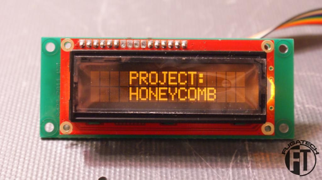
Project: Honeycomb
- Thread starter Fuganater
- Start date
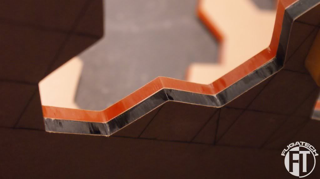
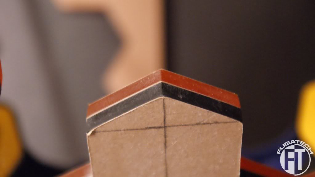
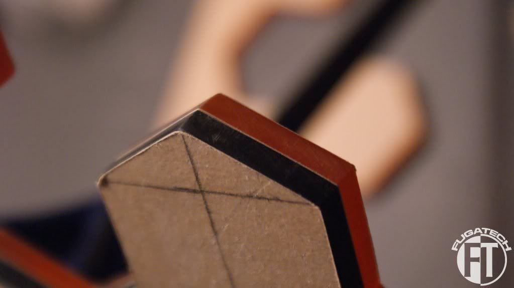
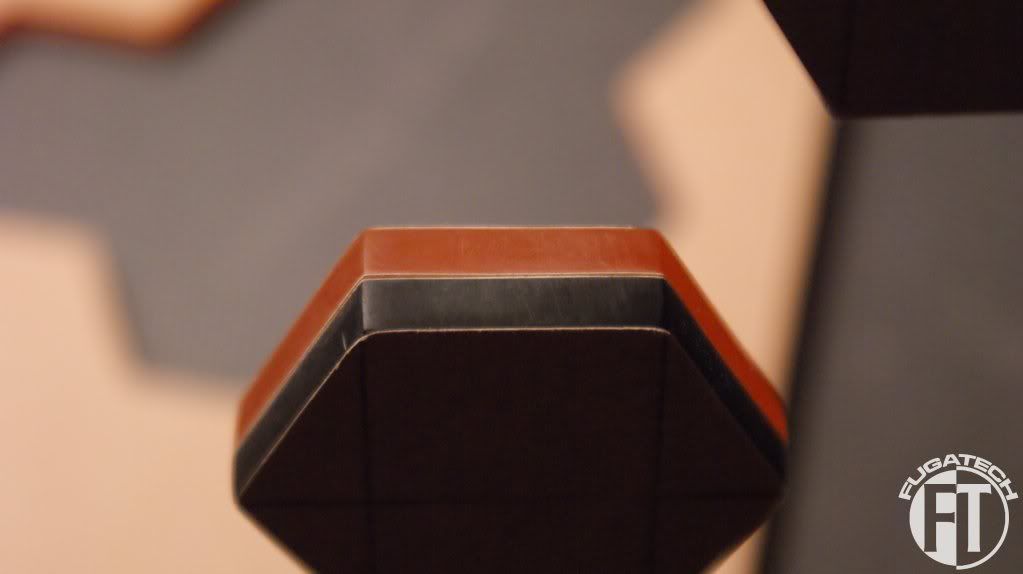
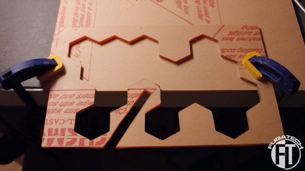
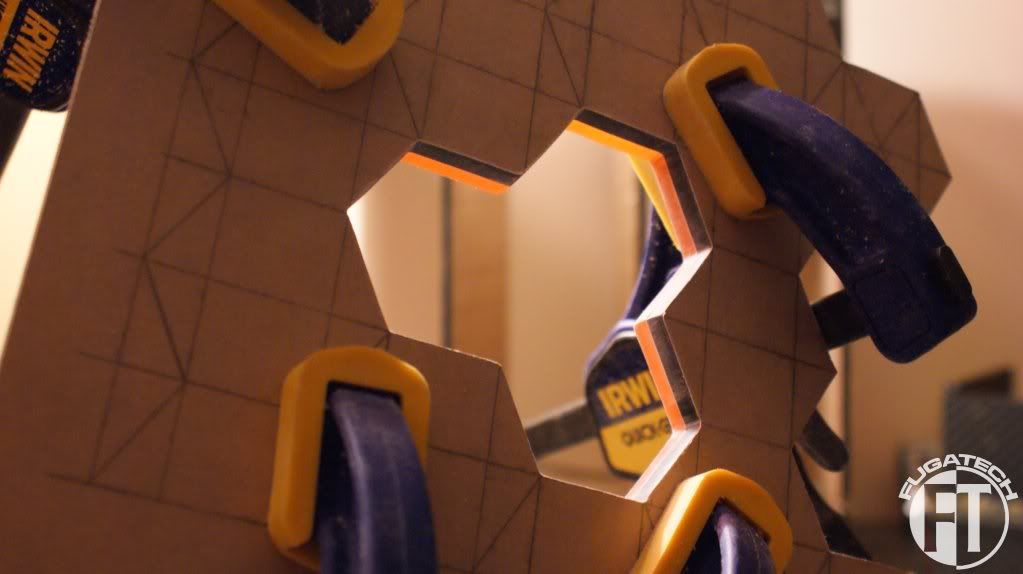
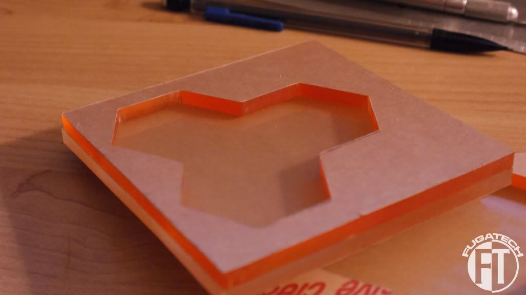
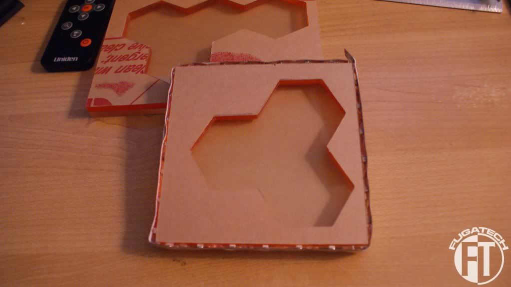
I got more work done on the side panel last night.
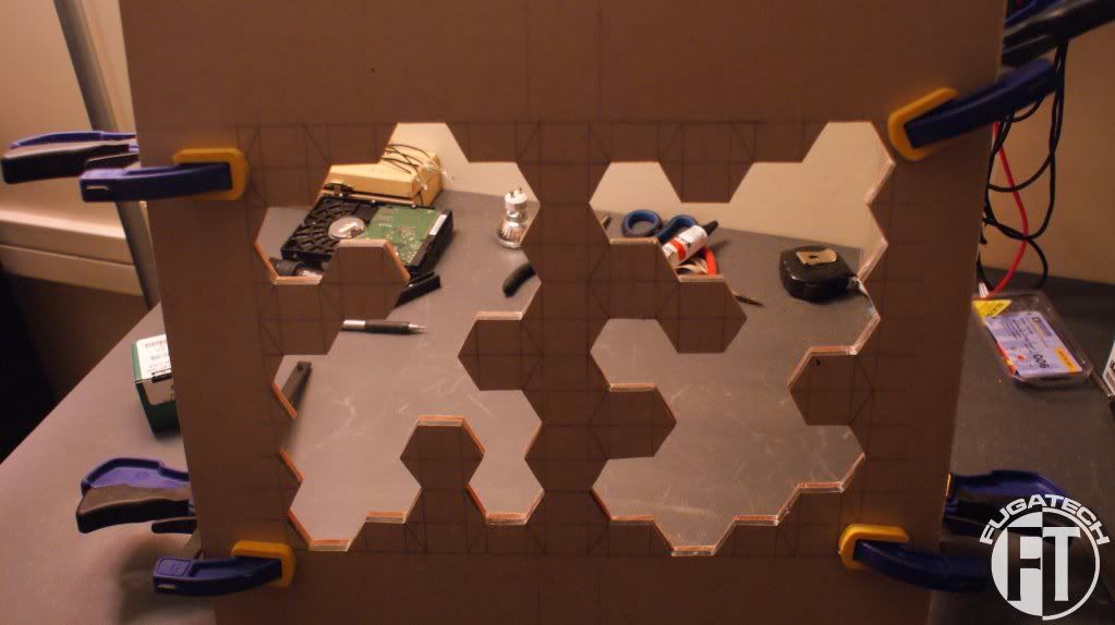
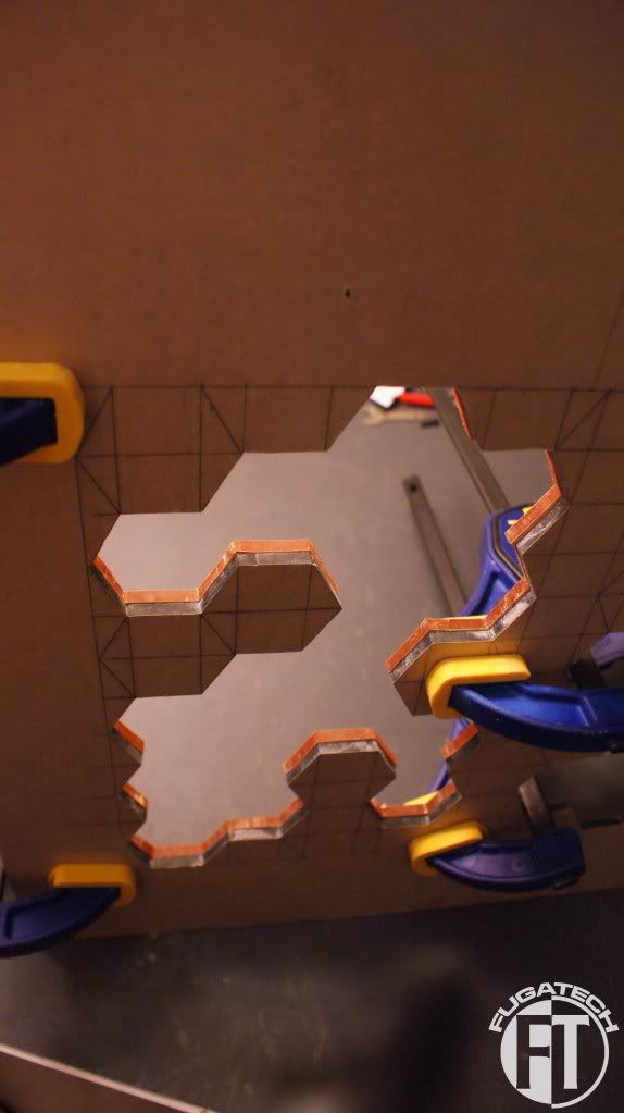
What I did was clamp the orange pieces to the main panel and lined them up as best I could. Then I filed down all the edges so that they were perfect. Then I sanded each edge with 200 grit to get most of the big scratches from the files out. I still have to sand a bit more but its pretty much done.
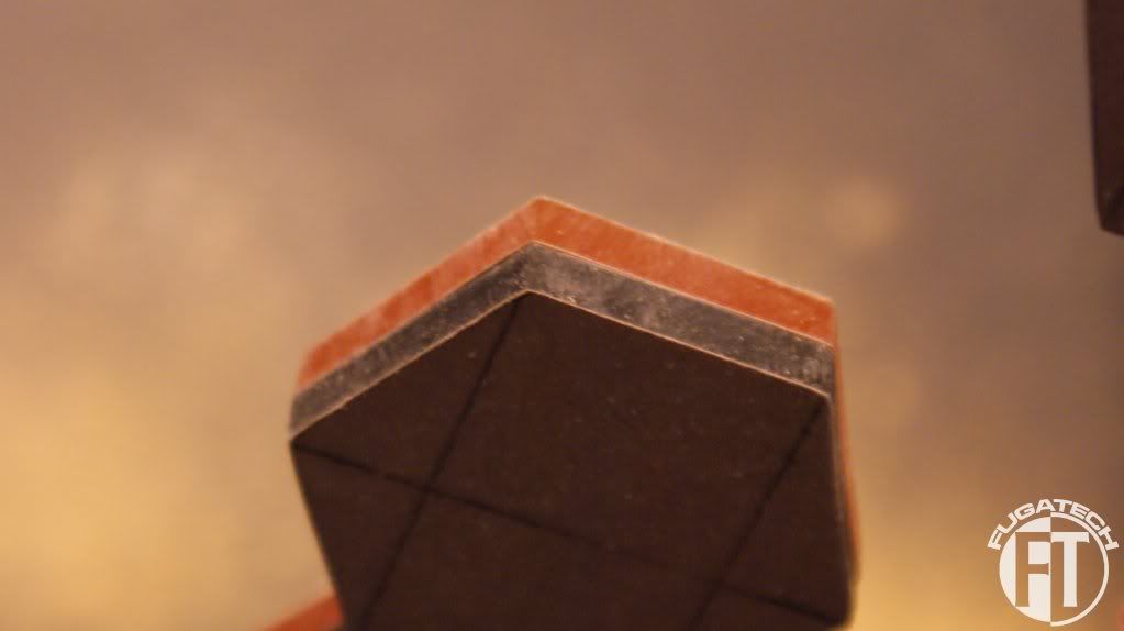
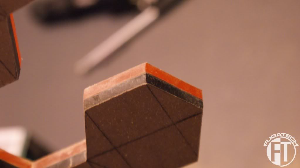
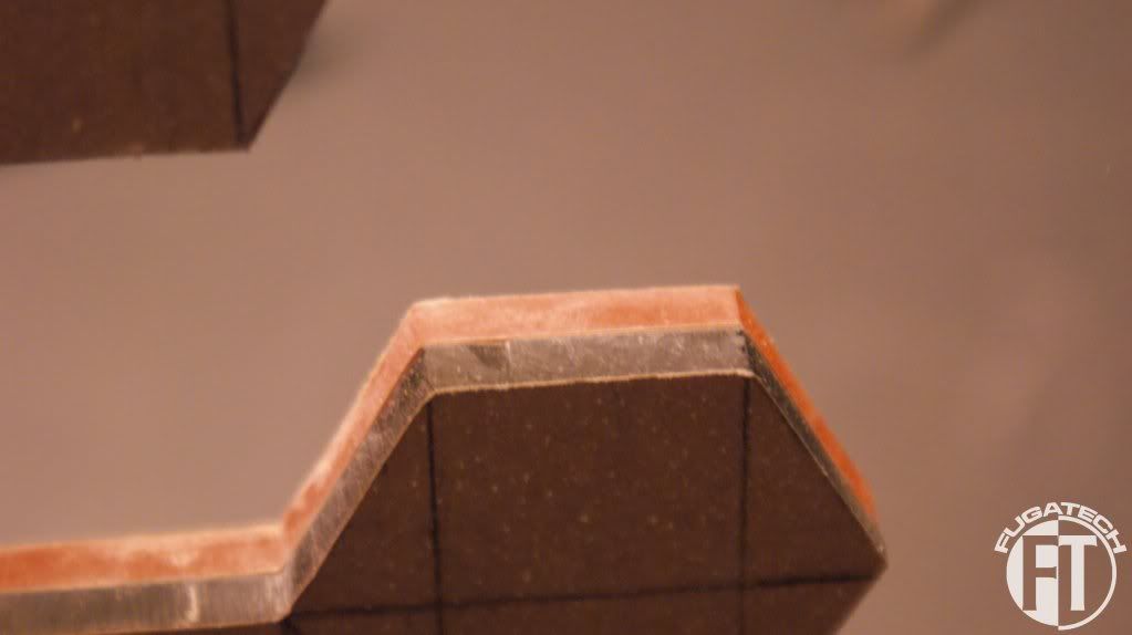
Once I finish the edges I will glue them to the main piece and then glue on the clear piece. I don't think I will get the lighting done before the 20th for the competition but I can try. More work to come very soon.
Cheers till then.
What I did was clamp the orange pieces to the main panel and lined them up as best I could. Then I filed down all the edges so that they were perfect. Then I sanded each edge with 200 grit to get most of the big scratches from the files out. I still have to sand a bit more but its pretty much done.
Once I finish the edges I will glue them to the main piece and then glue on the clear piece. I don't think I will get the lighting done before the 20th for the competition but I can try. More work to come very soon.
Cheers till then.
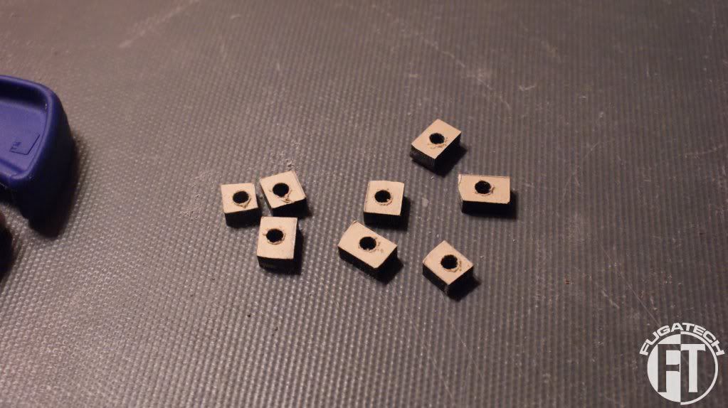
I made some feet for the HDD cages. I glued them on. I hope they hold if not I will have to use a different acrylic glue.
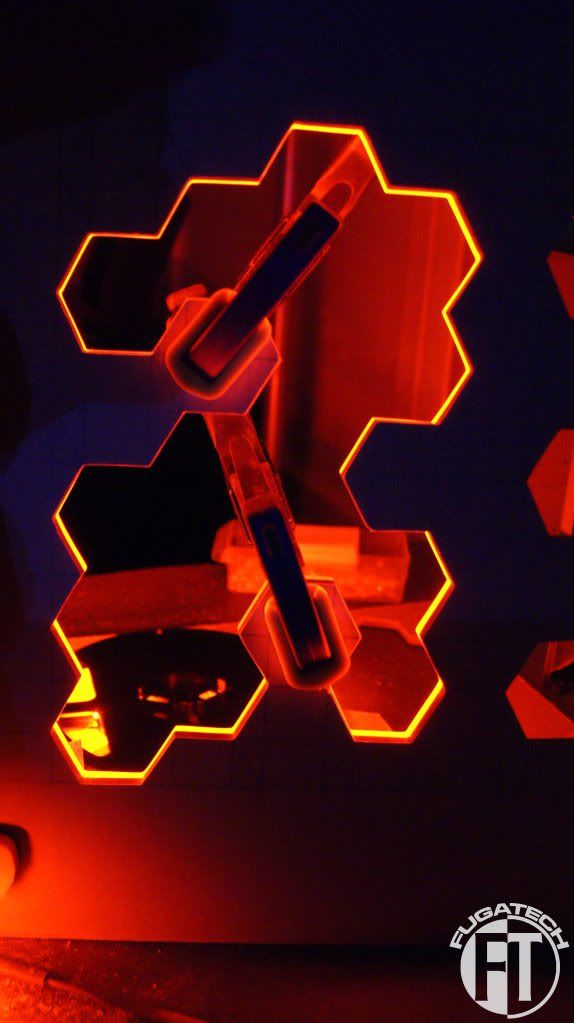
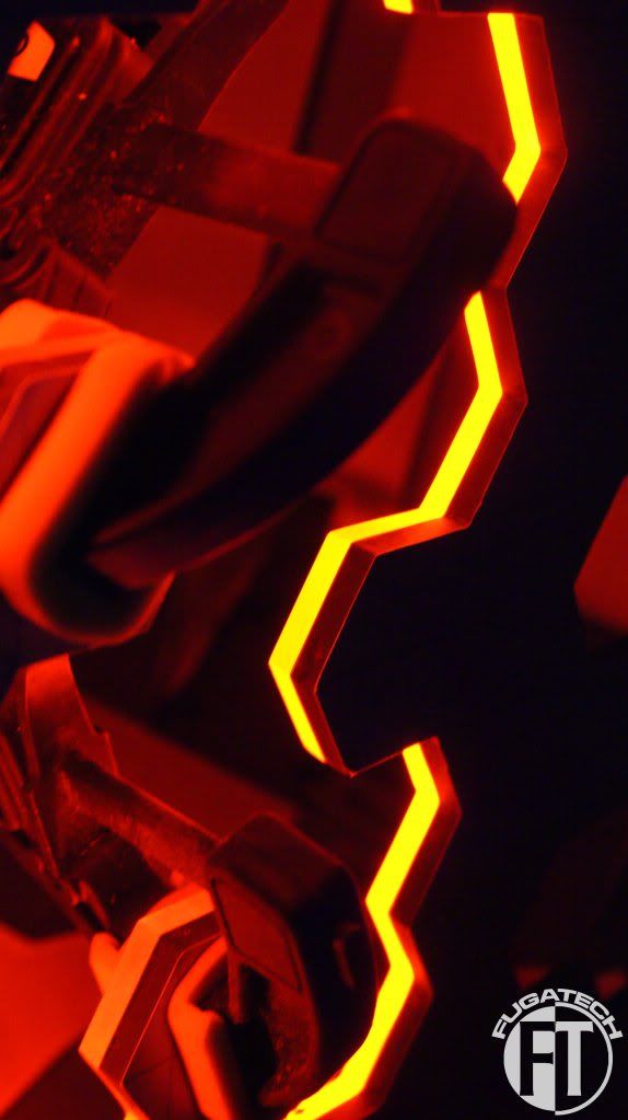
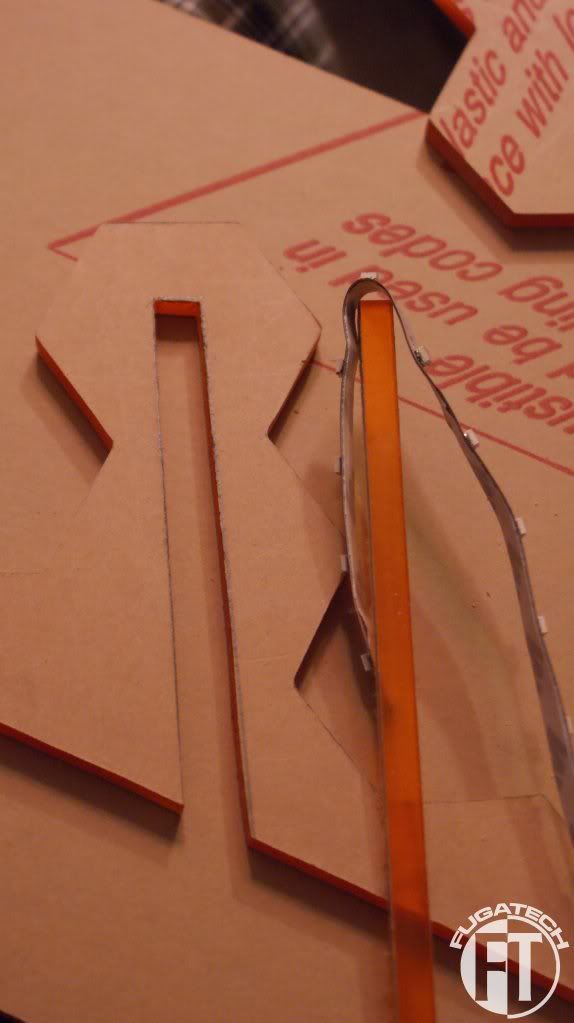
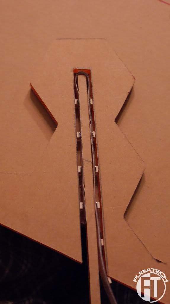
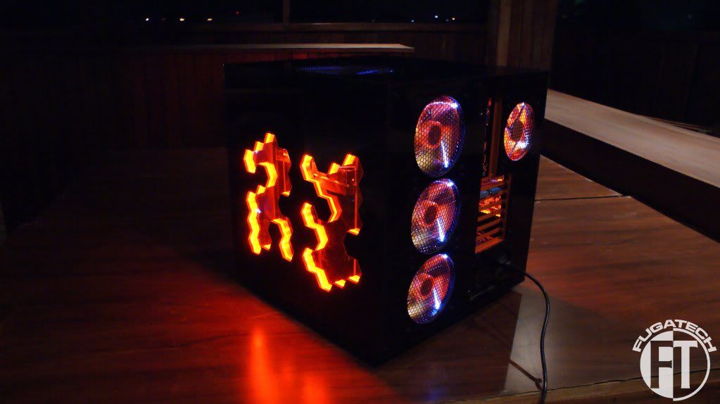
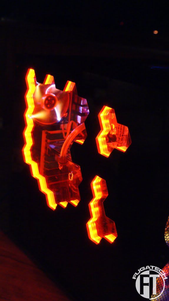
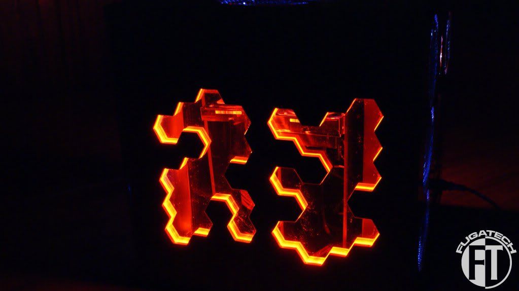
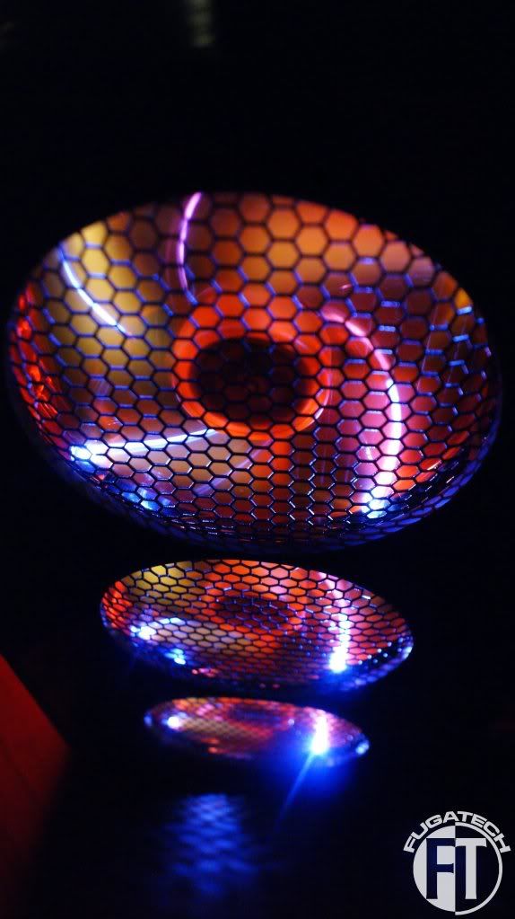
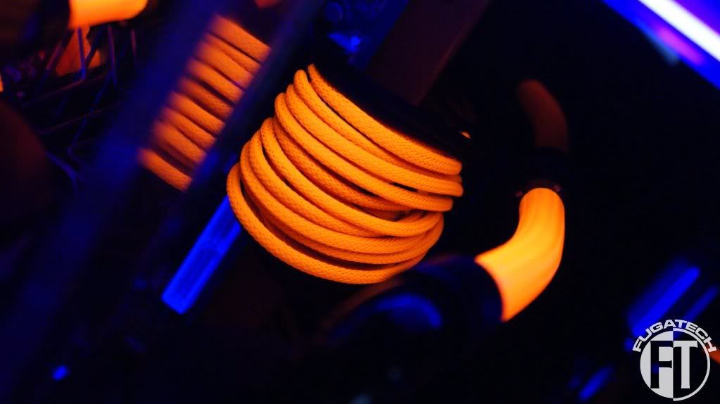
Now lighting.... Firstly, here is what it looks like.
I wrapped the Orange SMD LED strip around the orange piece of plexi.
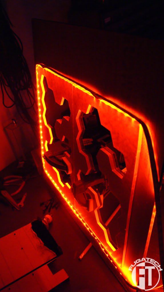
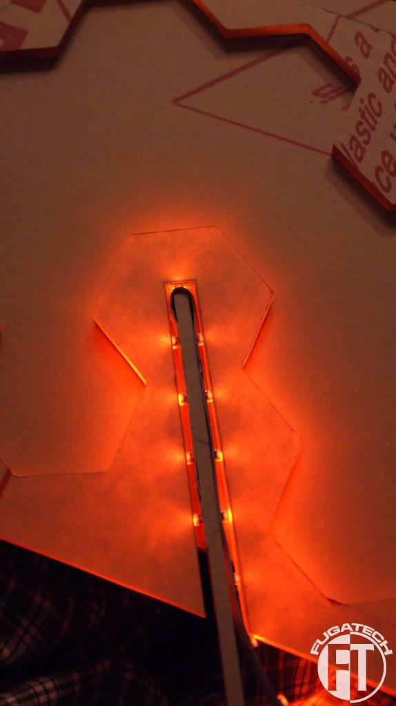
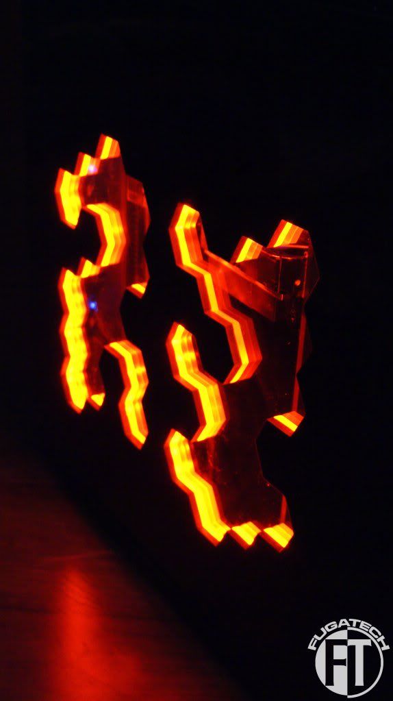
And here is the effect
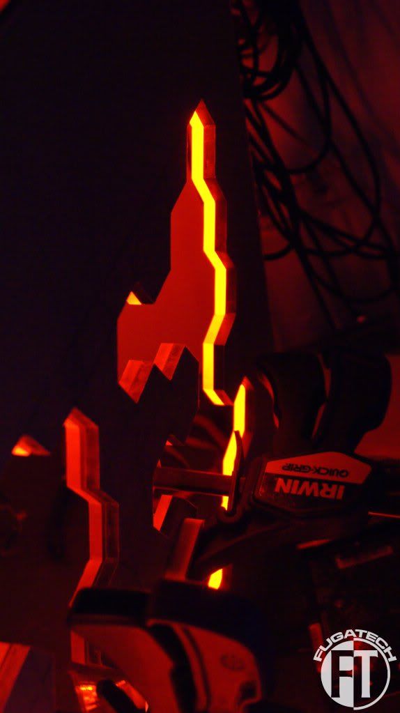
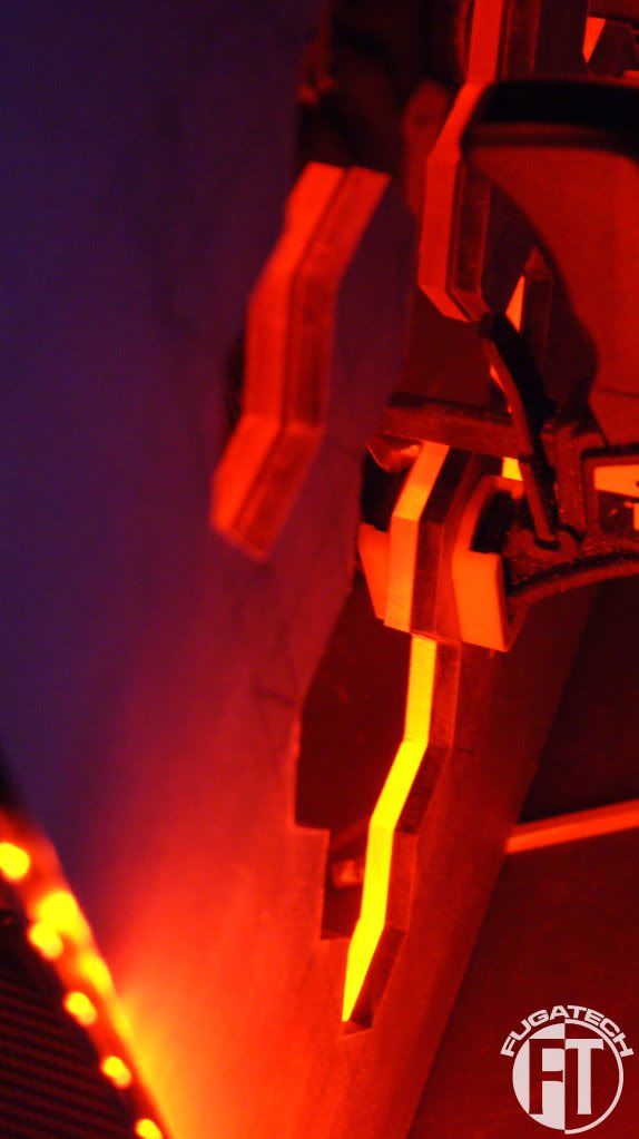
You can see how the pieces that stick out don't have any light going through them... How can I fix this? Also the inner side of both windows have no light. I might have to shave off enough of each window piece that I can wedge the LED strips between them so I can get the lighting. But I still have the same problem, no light on the 3 pieces that jut out.
Thoughts??
Now lighting.... Firstly, here is what it looks like.
I wrapped the Orange SMD LED strip around the orange piece of plexi.
And here is the effect
You can see how the pieces that stick out don't have any light going through them... How can I fix this? Also the inner side of both windows have no light. I might have to shave off enough of each window piece that I can wedge the LED strips between them so I can get the lighting. But I still have the same problem, no light on the 3 pieces that jut out.
Thoughts??
omegatotal
Gawd
- Joined
- Mar 15, 2002
- Messages
- 672
Only way I can think of is to cut a small opening (circle would be easiest right) in the orange in the center of the 3 exposed pieces that do not have any light, put a small ring of that same orange SMD LED strip in there and run a thin enough AWG wire for the lights.
Not sure if that will work with your idea for the finalized side panel
Not sure if that will work with your idea for the finalized side panel
Only way I can think of is to cut a small opening (circle would be easiest right) in the orange in the center of the 3 exposed pieces that do not have any light, put a small ring of that same orange SMD LED strip in there and run a thin enough AWG wire for the lights.
Not sure if that will work with your idea for the finalized side panel
This, Its looking great by the way.
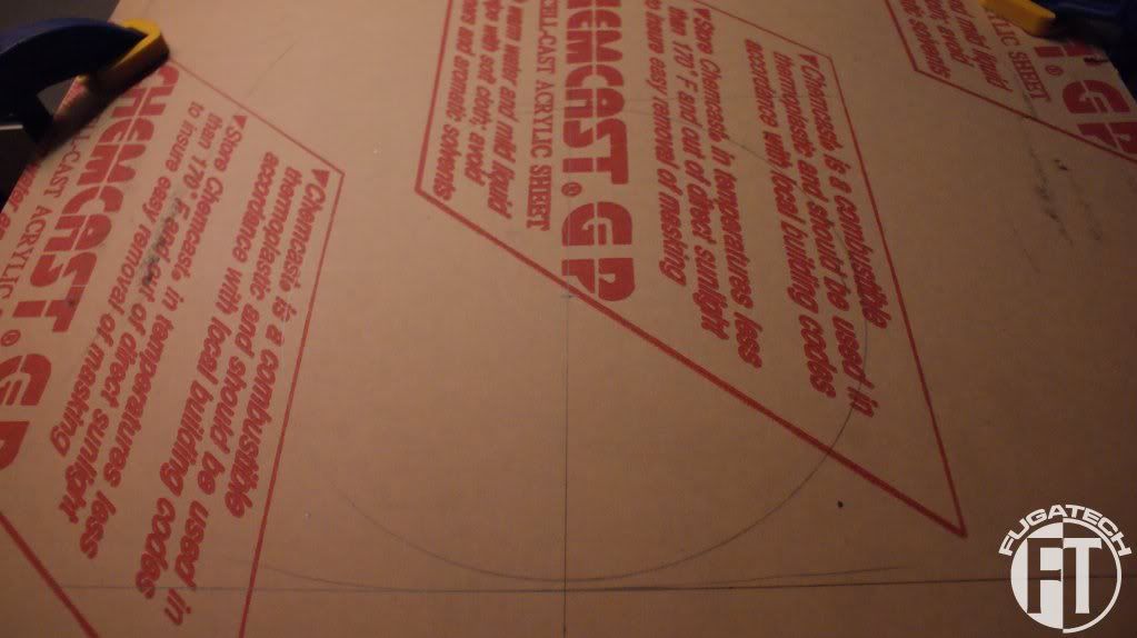
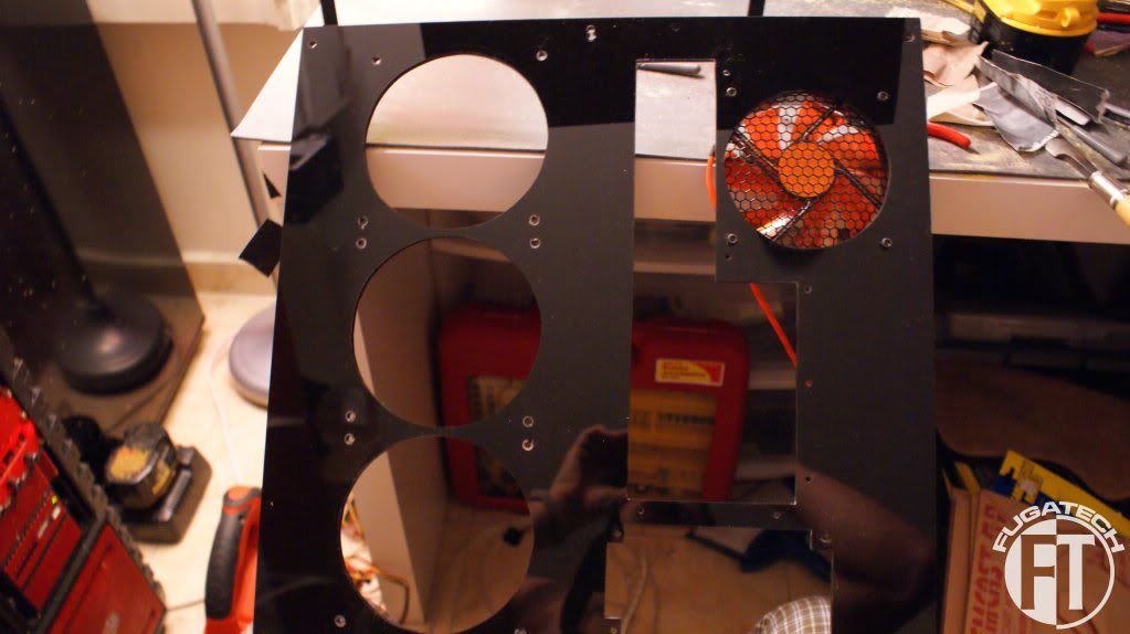
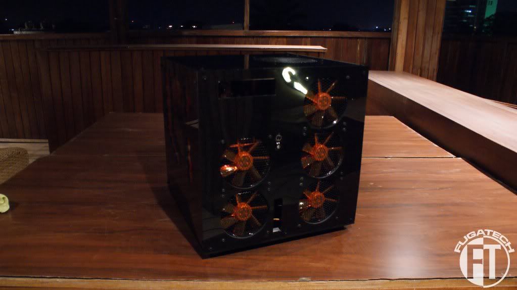
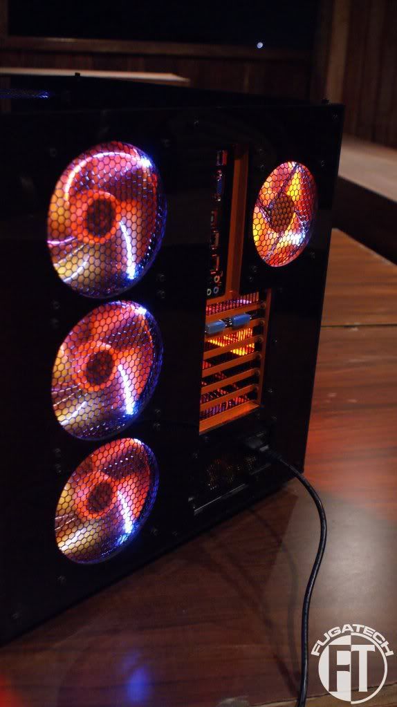
Here are the pictures of the PSU shroud I promised.
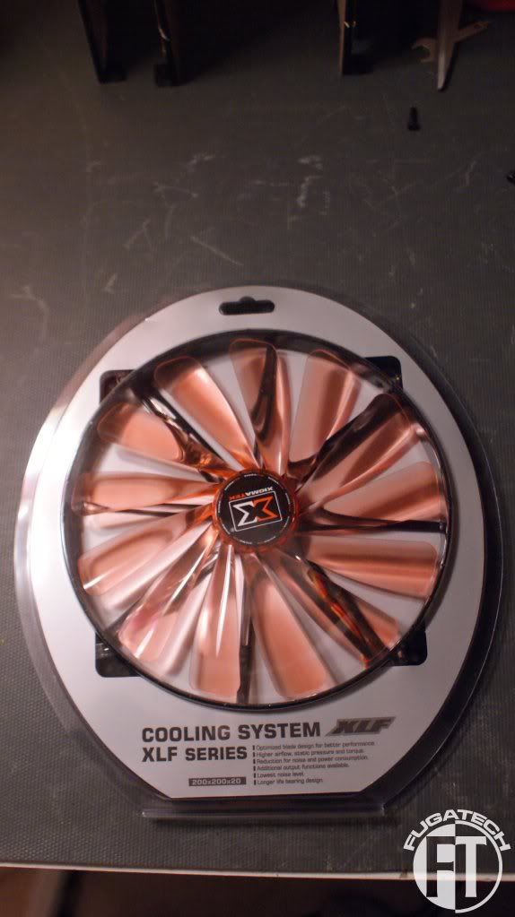
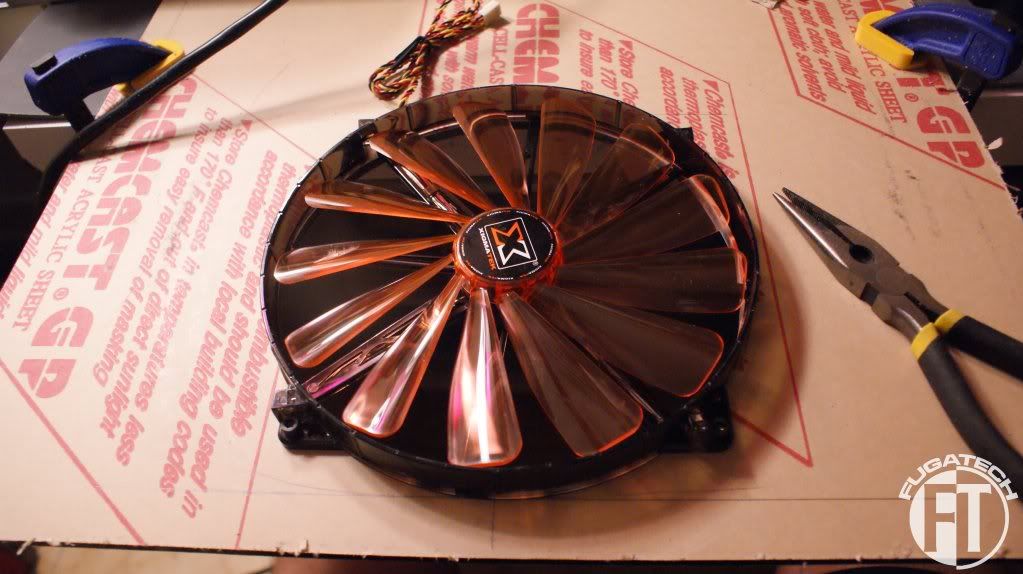
I got a 200mm fan to exhaust the HDD side of the case.
Hole drawn for cutting
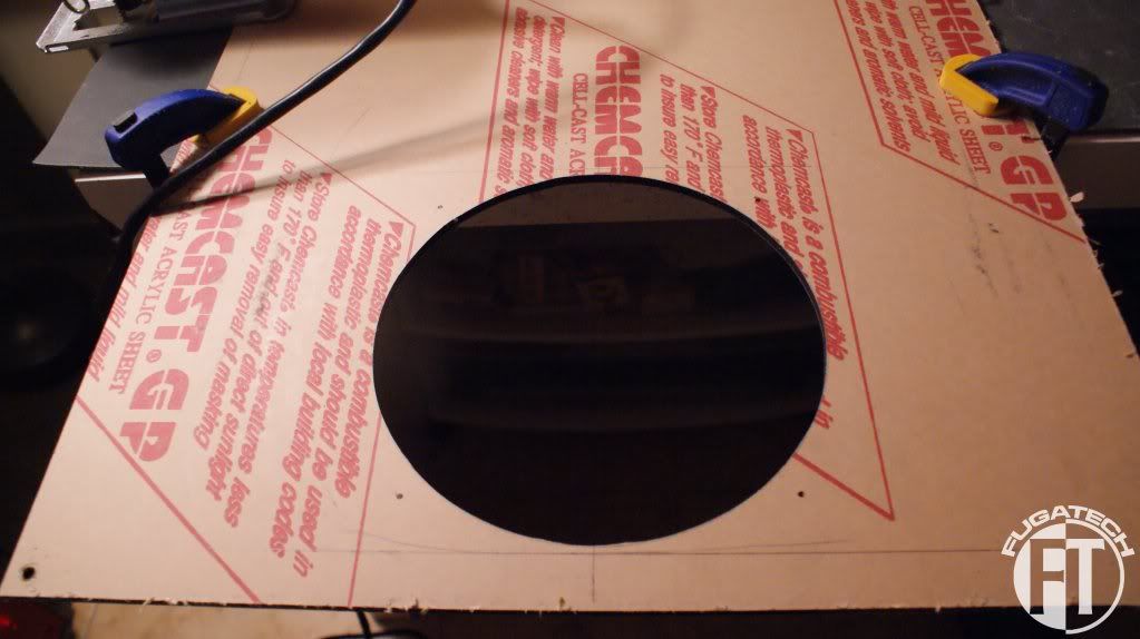
Cut and sanded
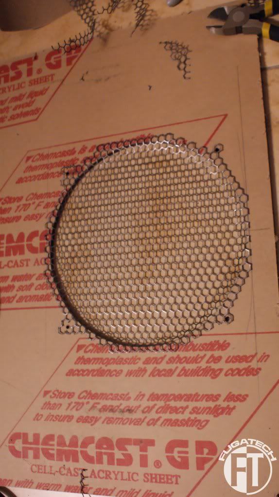
Add a Modders Mesh fan grill
And the fan
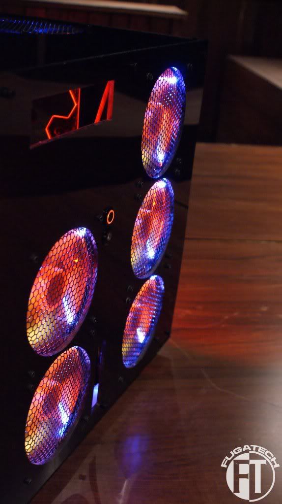
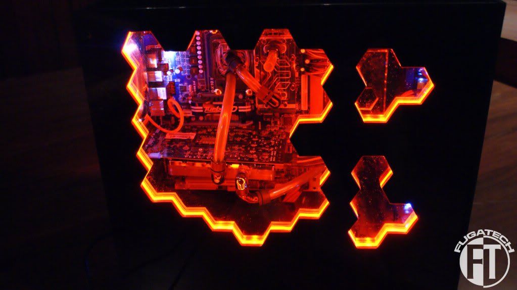
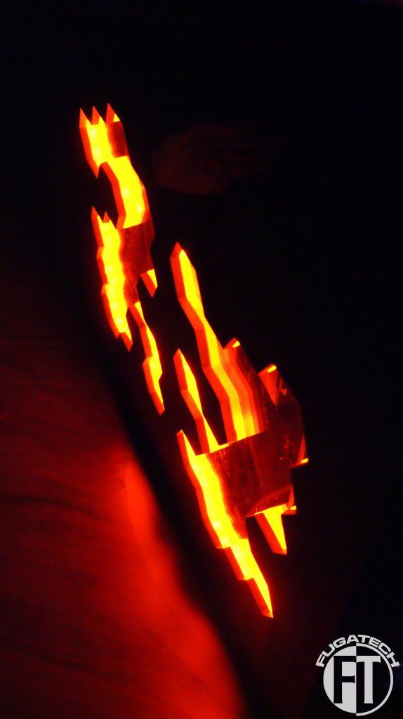
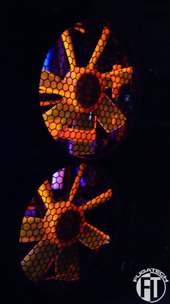
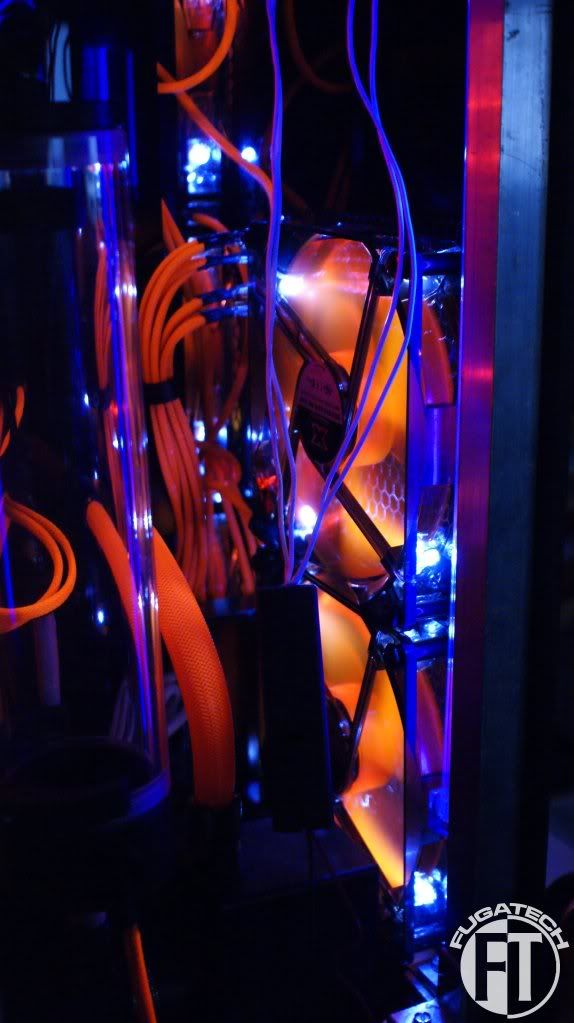
Here are a few more pics of the lighting.
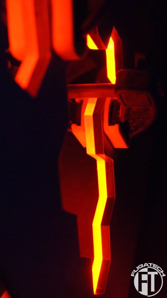
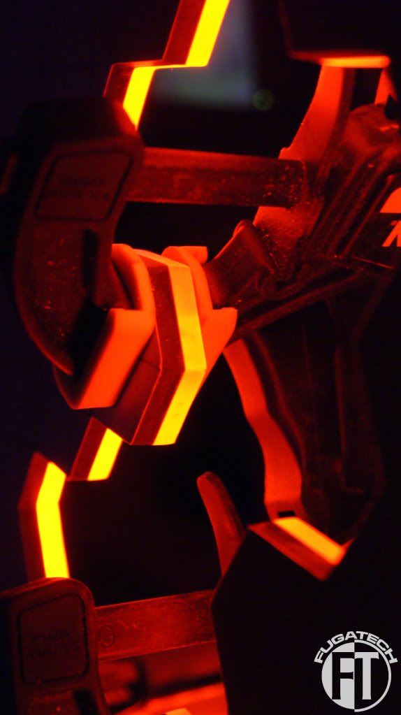
I've been sanding for probably 20 hours to get everything nice and smooth.
Now to get light to pass through the hexagons that are extended I had to cut a strip in the back so I could put the LEDs in there.
I took the LED strip and a piece of scrap plexi.
Wedged them in to the slot I cut
And voila! Works perfectly.
I'm working on the mobo side panel now
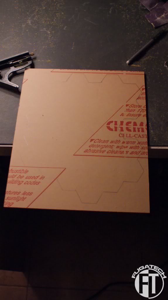
Here is the orange layer for the main mobo side window
And finally I'm starting to attach things to the back plate.
I'm trying really really hard to finish before tonight.
Cheers till next time.
I got a 200mm fan to exhaust the HDD side of the case.
Hole drawn for cutting
Cut and sanded
Add a Modders Mesh fan grill
And the fan
Here are a few more pics of the lighting.
I've been sanding for probably 20 hours to get everything nice and smooth.
Now to get light to pass through the hexagons that are extended I had to cut a strip in the back so I could put the LEDs in there.
I took the LED strip and a piece of scrap plexi.
Wedged them in to the slot I cut
And voila! Works perfectly.
I'm working on the mobo side panel now
Here is the orange layer for the main mobo side window
And finally I'm starting to attach things to the back plate.
I'm trying really really hard to finish before tonight.
Cheers till next time.
So here is the final working update for the New Mod City Showdown Competition. The case is done but I still have work to do on the inside so stay tuned for that. I'm sorry that its small but due to the deadline I didn't take many pictures today.
Here are the small windows. I glued the clear piece of acrylic to the orange.
Then attached the Orange SMD LED strips
And attached those pieces to the case and wired them up.
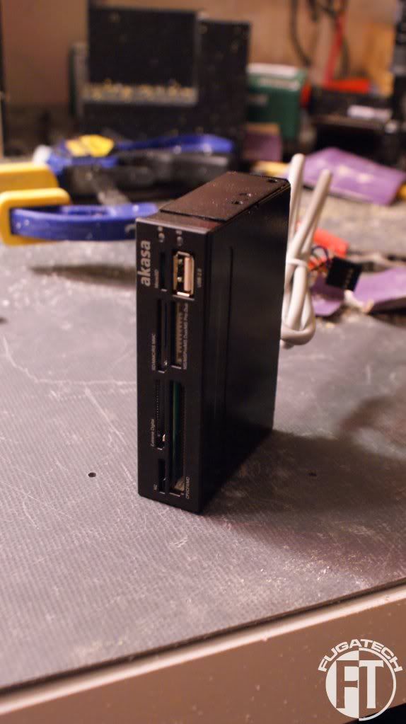
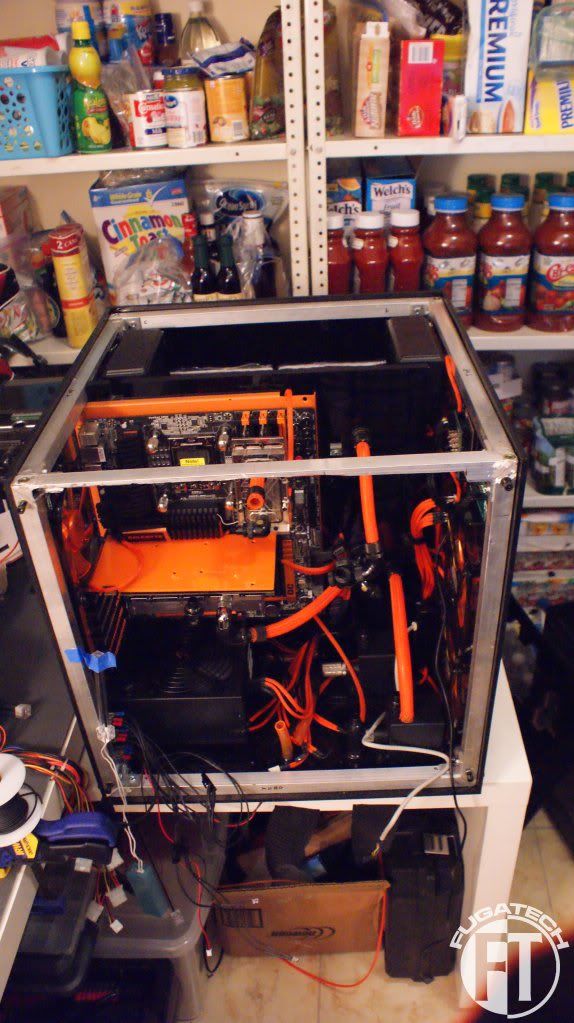
Here is the Media Card Reader all painted and cut up. Its about 1/3 its original length.
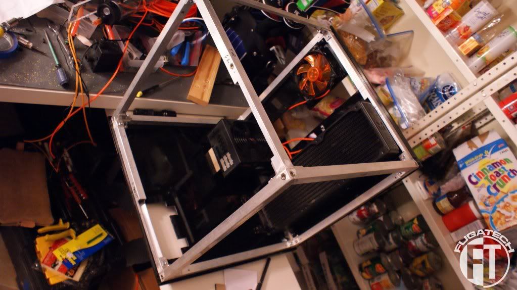
And just one last picture of the case all stripped while I was working on the panels
I'll post the pictures of the case in the next update.
Here are the small windows. I glued the clear piece of acrylic to the orange.
Then attached the Orange SMD LED strips
And attached those pieces to the case and wired them up.
Here is the Media Card Reader all painted and cut up. Its about 1/3 its original length.
And just one last picture of the case all stripped while I was working on the panels
I'll post the pictures of the case in the next update.
I started wiring up the waterblocks with LEDs.
GPU Block
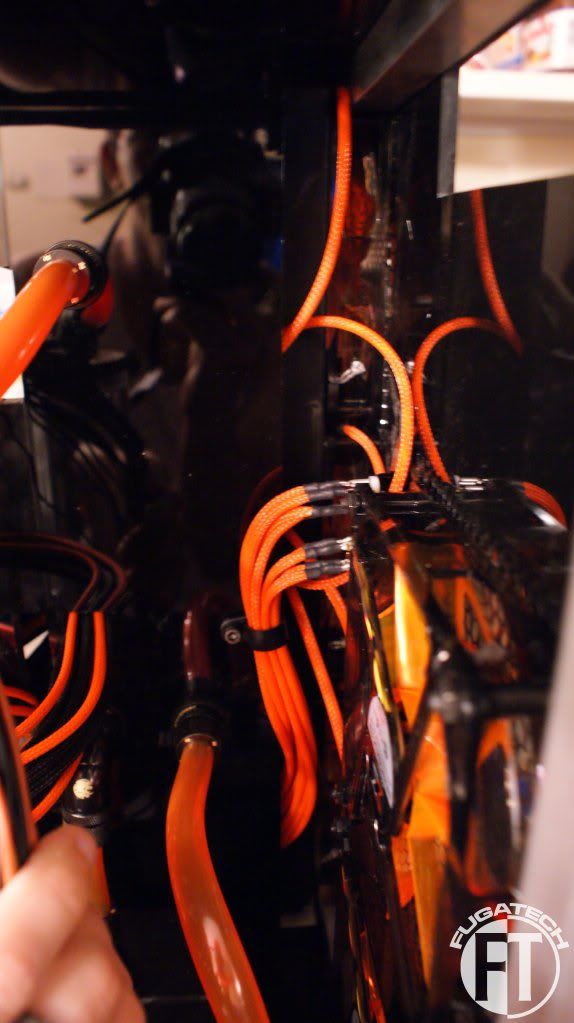
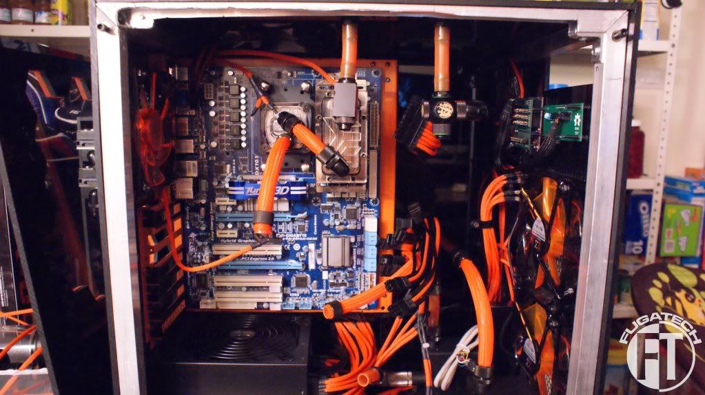
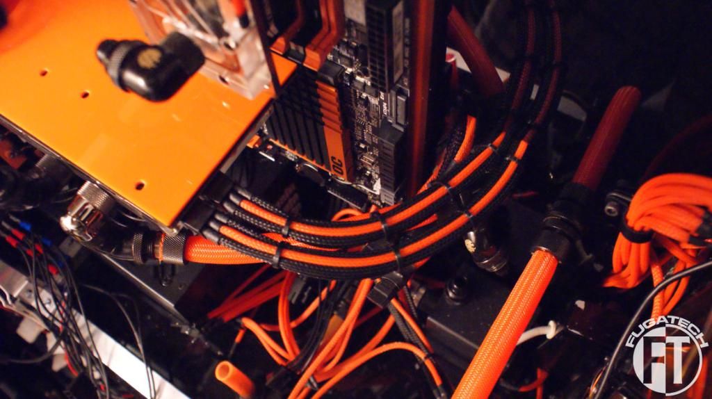
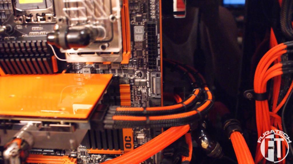
Cable management time! I'm using P clips from MDPC-X which are working rather well. I also finished up the pluming.
Back fan cables
Front fan cables
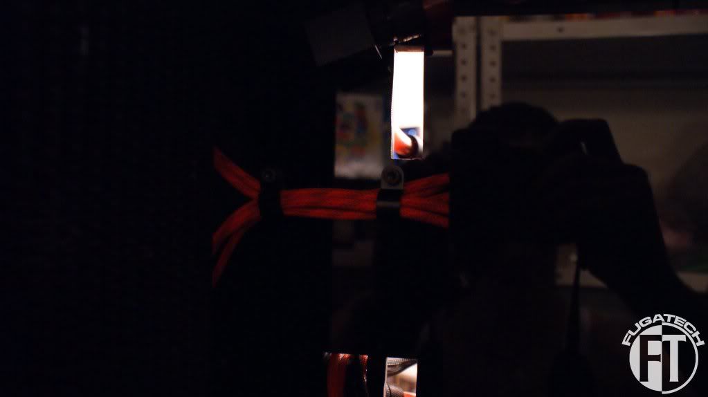
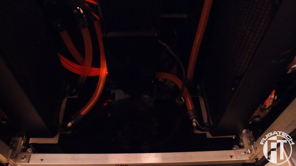
Left side of HDD cavity where most of the pluming comes through the center of the case
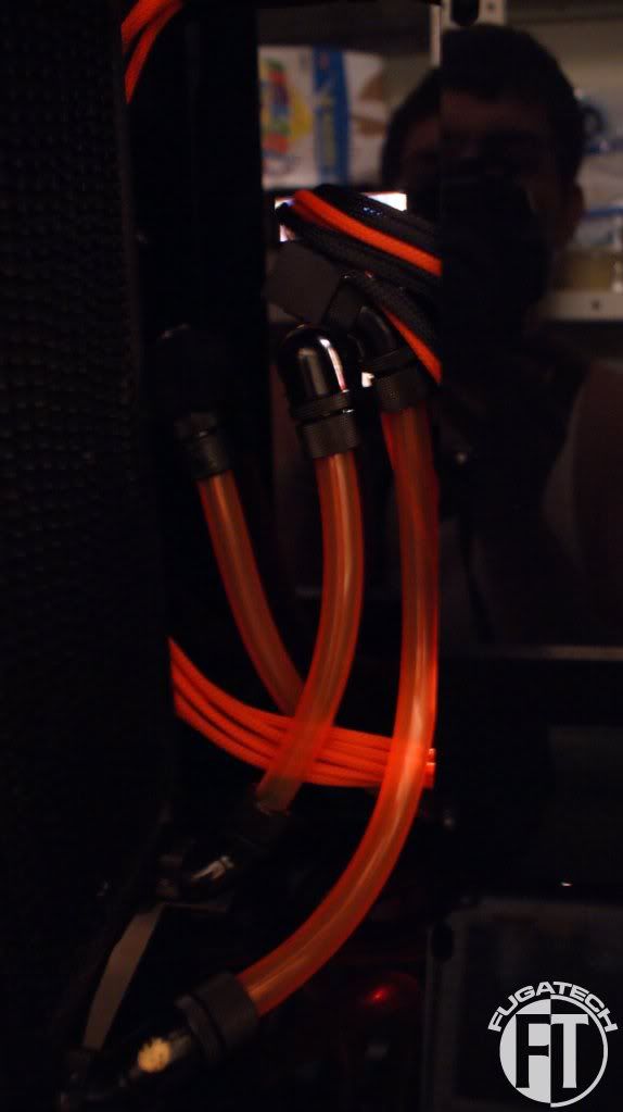
Another shot of the right side of the HDD cavity
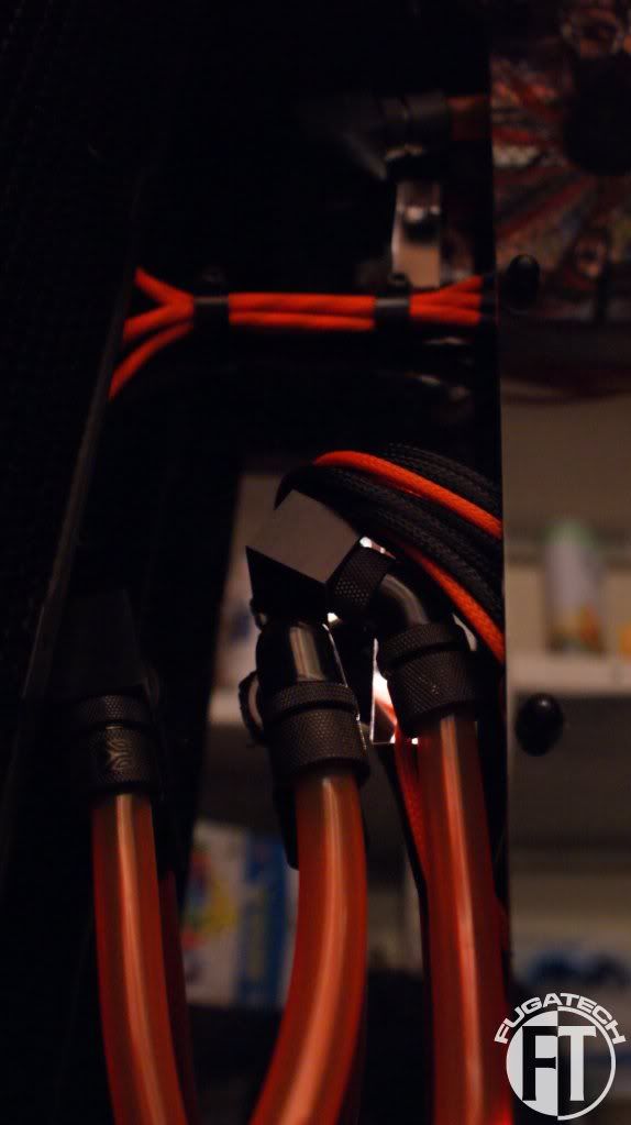
Bottom of the case
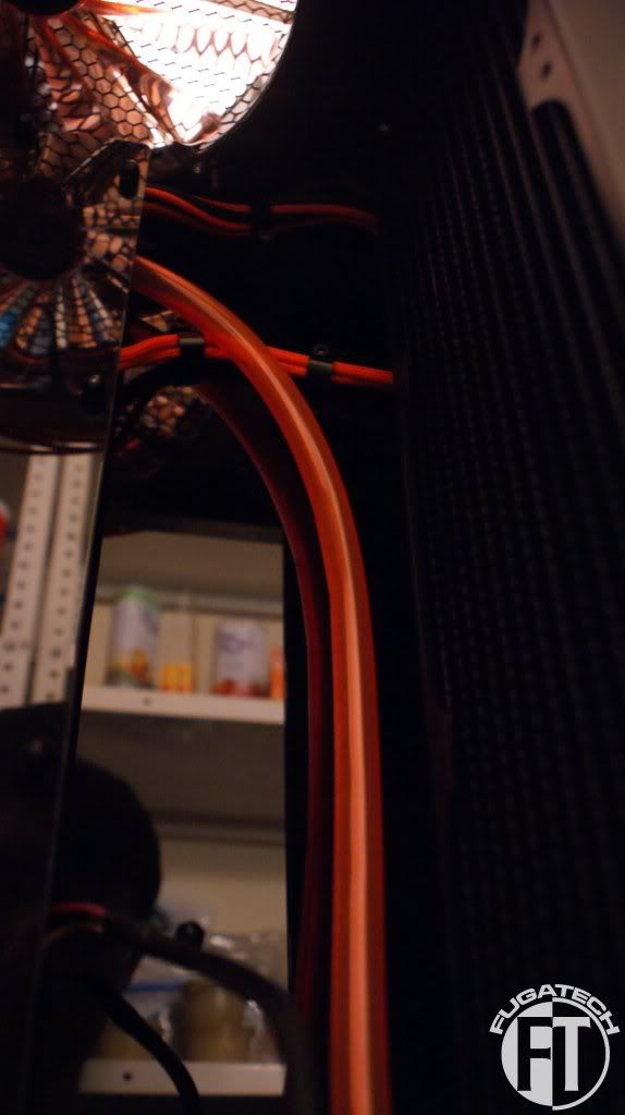
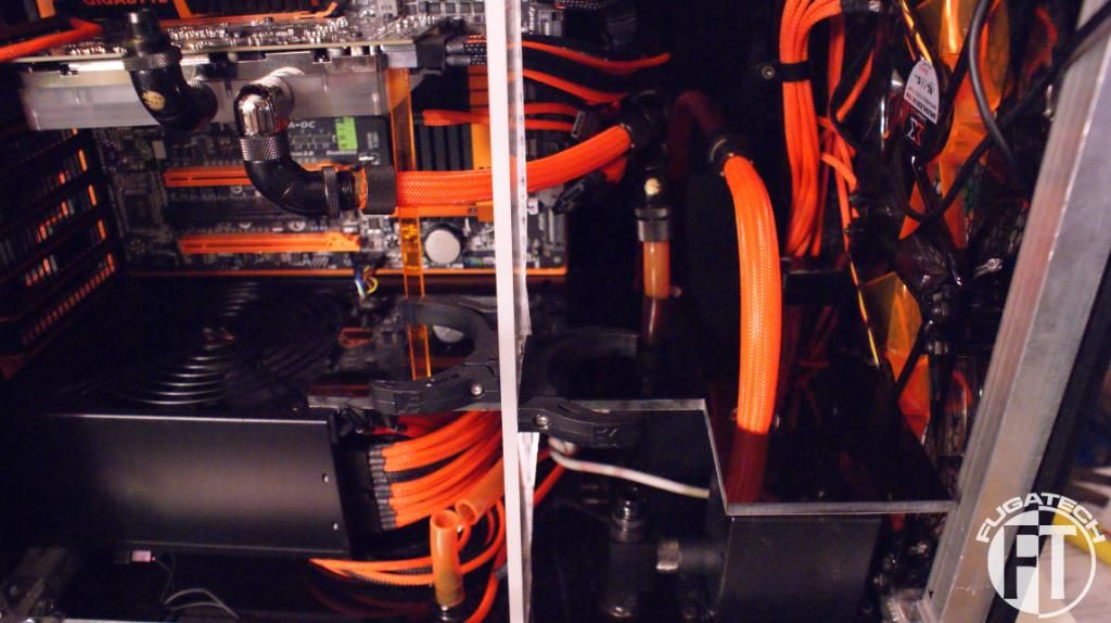
Some cable management on the mobo side
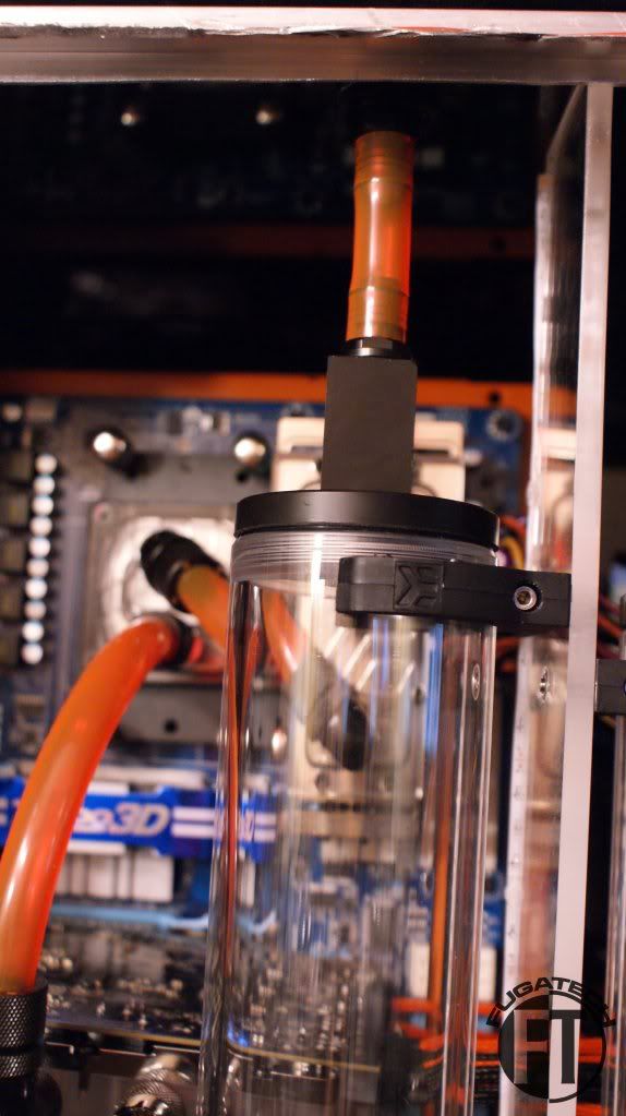
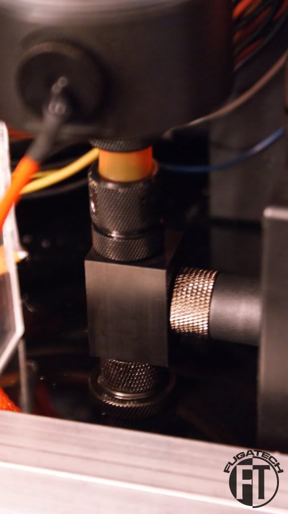
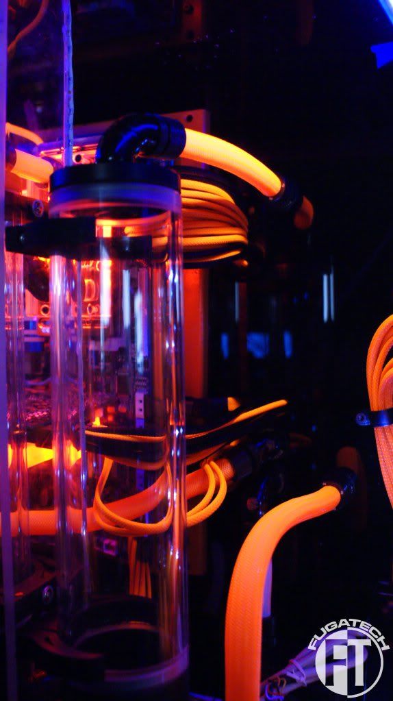
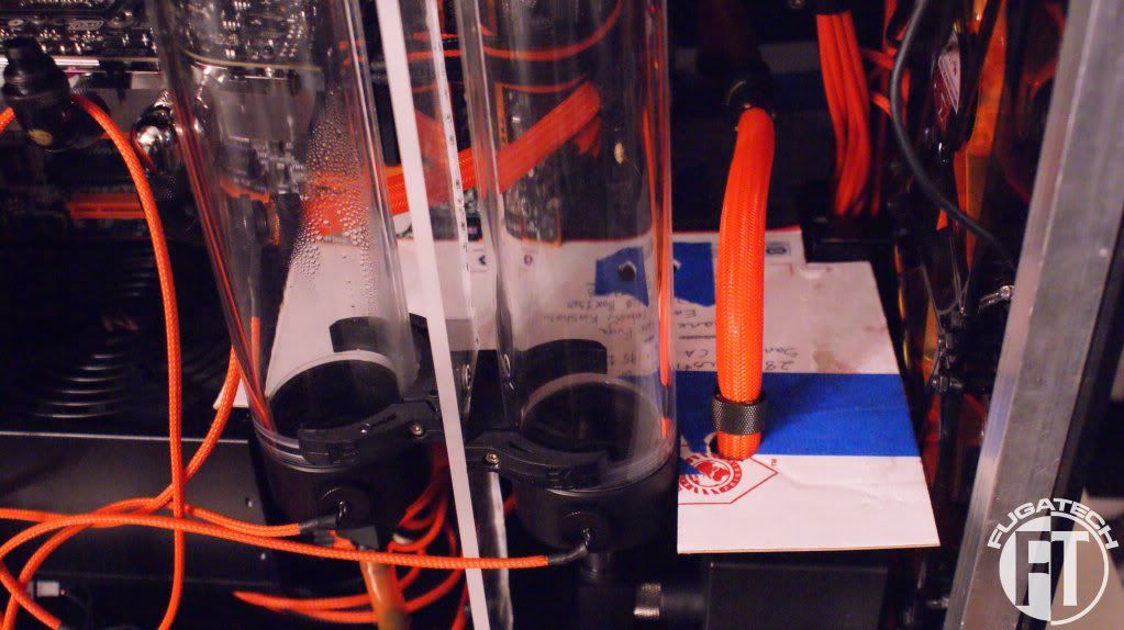
T-fitting on top of the mobo loop res. This attaches to the fill port on top of the case
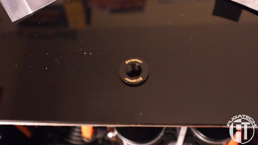
And here is the drain port for the HDD loop res. Luckily I was able to use fittings and no tubing which made the installation super easy.
I'm doing lots more work this week.
Cheers till later!
GPU Block
Cable management time! I'm using P clips from MDPC-X which are working rather well. I also finished up the pluming.
Back fan cables
Front fan cables
Left side of HDD cavity where most of the pluming comes through the center of the case
Another shot of the right side of the HDD cavity
Bottom of the case
Some cable management on the mobo side
T-fitting on top of the mobo loop res. This attaches to the fill port on top of the case
And here is the drain port for the HDD loop res. Luckily I was able to use fittings and no tubing which made the installation super easy.
I'm doing lots more work this week.
Cheers till later!
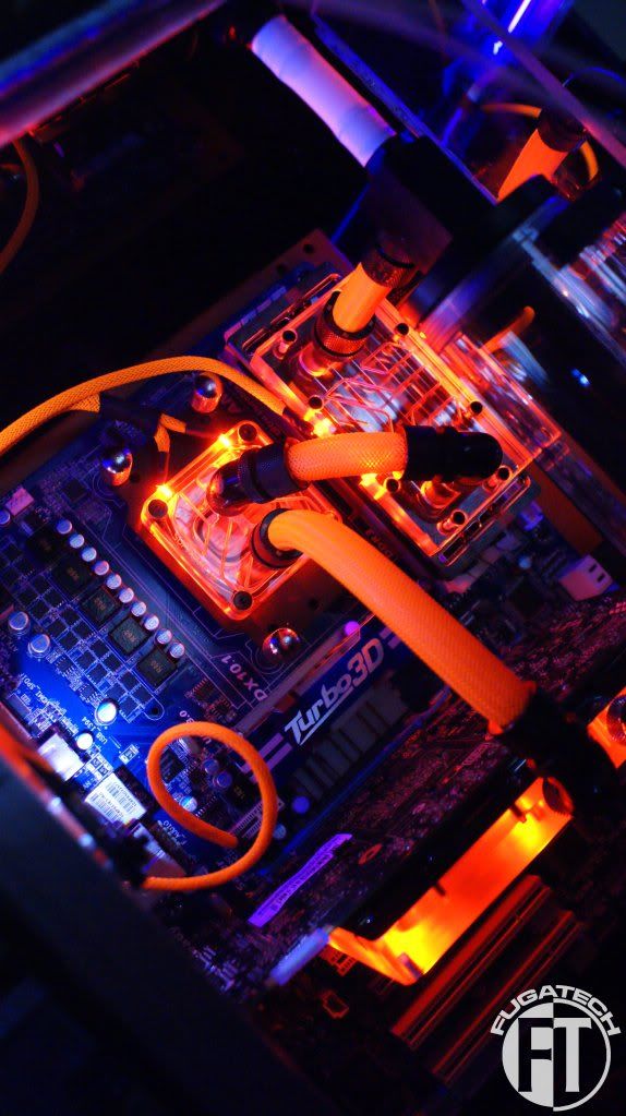
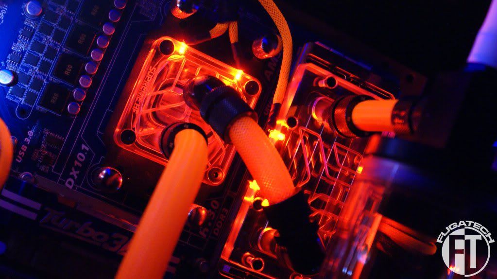
I finished the LEDs for the CPU and RAM blocks.
I'll clean up the cables a bit later.
And so far it all looks pretty good.
All that is left for LEDs is the ones that go in the bottom of the reservoirs.
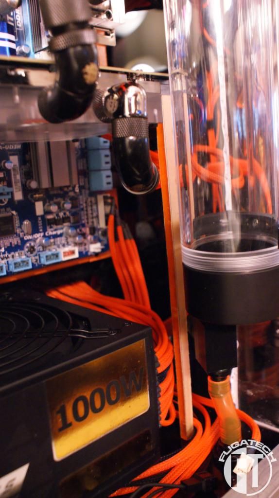
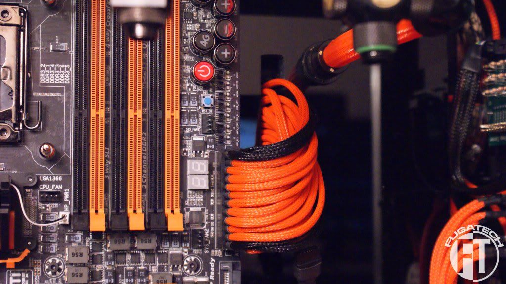
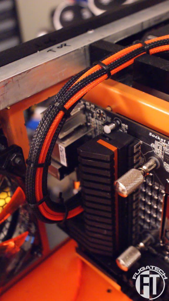
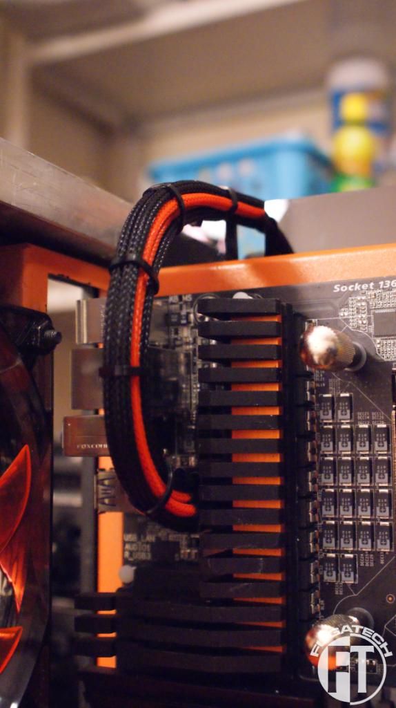
I finally finished and installed my custom ATX power cable. It still needs some work because it is bunched up. But that will come later.
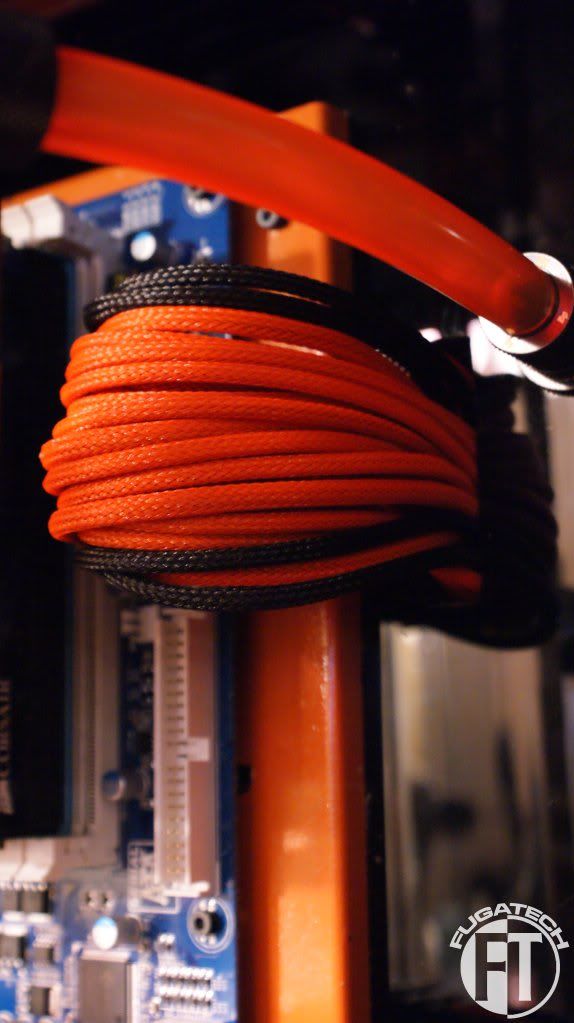
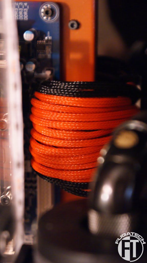
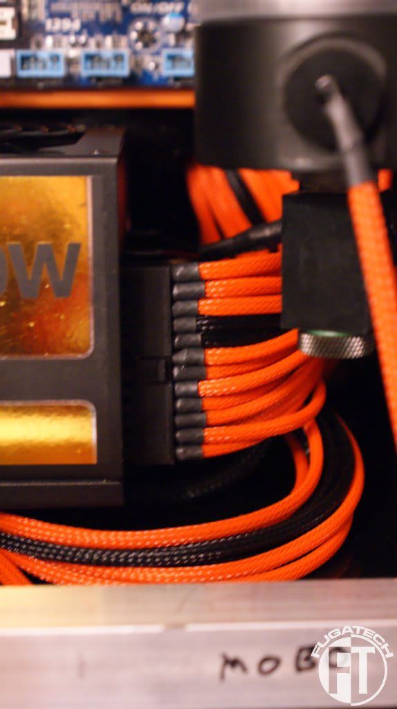
And here is what it looks like connected to the PSU
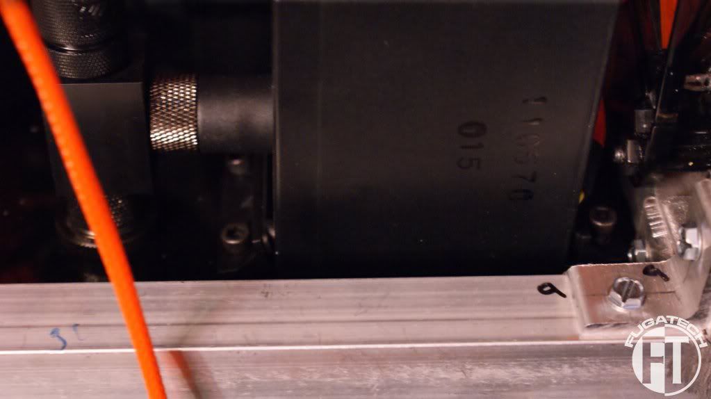
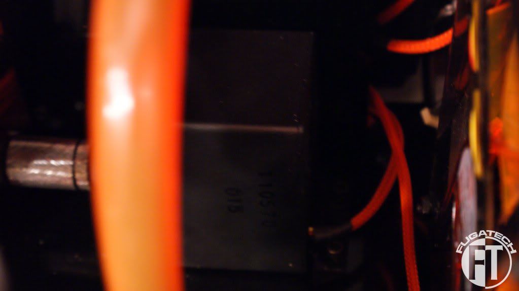
A very tricky task was to mount the pumps. Since I have no hand room inside the case at the bottom, I had to remove the entire bottom panel, mount the pumps, then put it back on. Here is the final result. (A bit hard to see...)
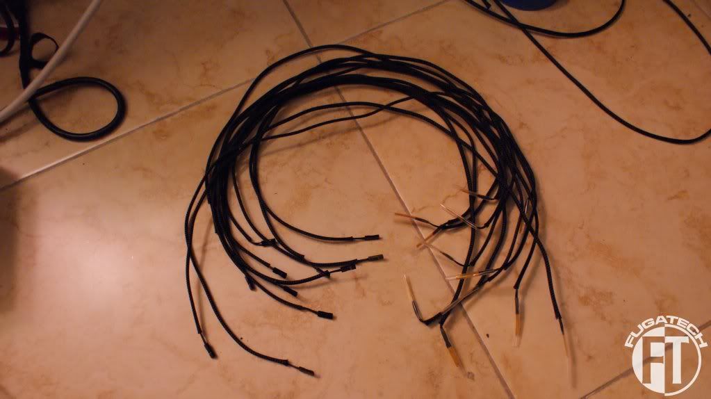
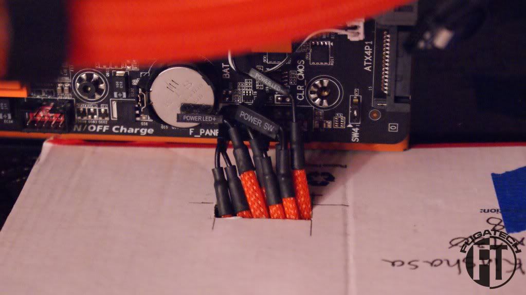
I started sleeving the temp sensors. There are a lot of them!
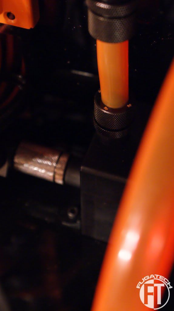
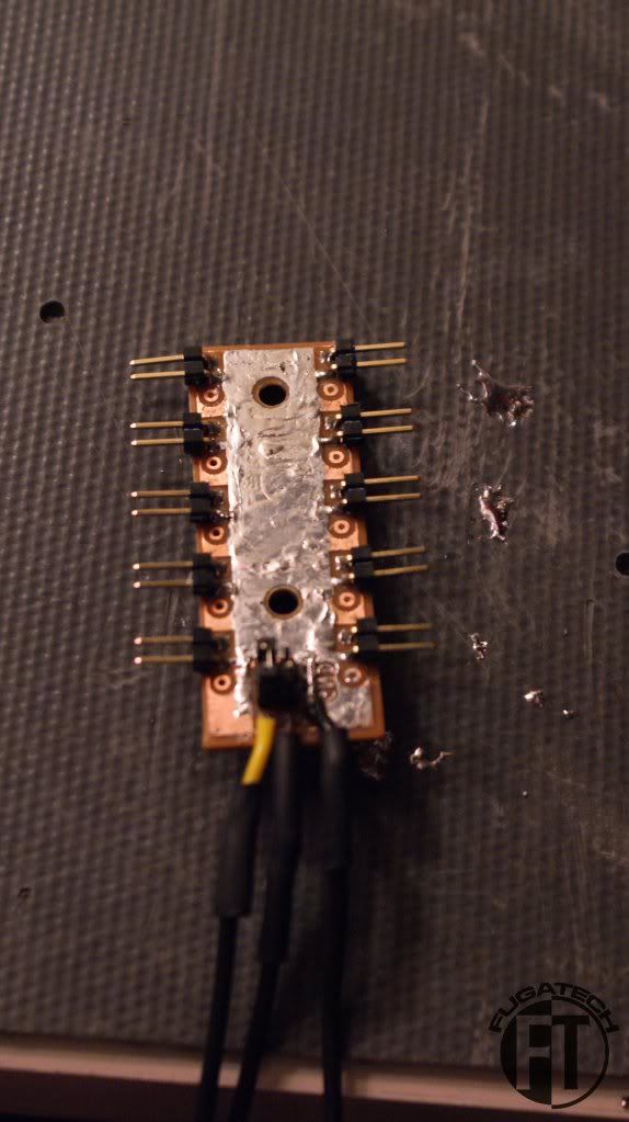
And finally, I had Will make a fan buss for me. The only problem with it is that I had to extend the power connector because where it is at is an extremely tight space and I can't get my fingers back there to connect it.
Cheers till next time.
I'll clean up the cables a bit later.
And so far it all looks pretty good.
All that is left for LEDs is the ones that go in the bottom of the reservoirs.
I finally finished and installed my custom ATX power cable. It still needs some work because it is bunched up. But that will come later.
And here is what it looks like connected to the PSU
A very tricky task was to mount the pumps. Since I have no hand room inside the case at the bottom, I had to remove the entire bottom panel, mount the pumps, then put it back on. Here is the final result. (A bit hard to see...)
I started sleeving the temp sensors. There are a lot of them!
And finally, I had Will make a fan buss for me. The only problem with it is that I had to extend the power connector because where it is at is an extremely tight space and I can't get my fingers back there to connect it.
Cheers till next time.
- Joined
- May 24, 2006
- Messages
- 17,029
Looks so sick! But what's with the weird angle of the video card?
reaper_1994
n00b
- Joined
- Mar 2, 2011
- Messages
- 55
+1 to the brace. WOW!!! the colour looks great but when I saw that GPU bending like that I was like "WTF!!!" 
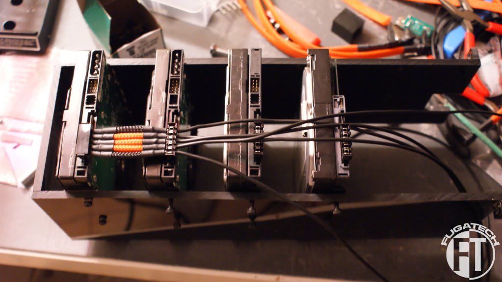
I started making my SATA power cables.
First, I installed all the drives. Put the SATA connectors on them. And started running the cables.
First section done.
More done.
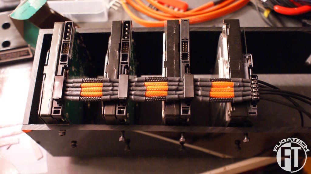
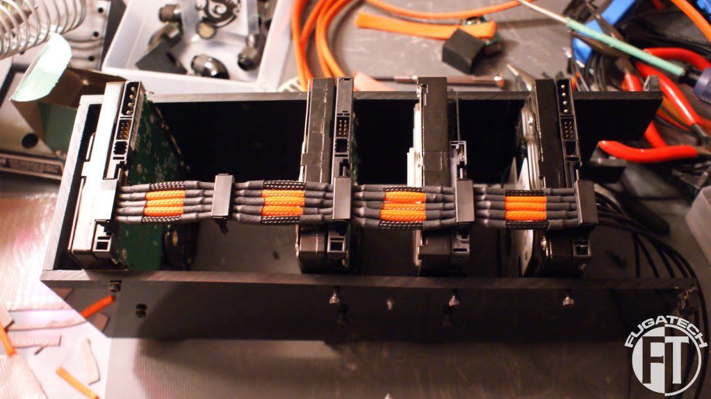
I had to move a drive down so I could measure the last section correctly.
And the final product with the sleeved SATA Data cables installed and zipped.
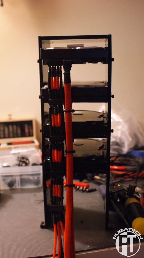
I'm happy with how they came out. I did the same thing for the other HDD cage but I ran out of heat shrink so I put another order in for it at MDPC-X. My ATX pin remover is also starting to go... I think I need to spend the money and get the good one.
Cheers till next time!
First, I installed all the drives. Put the SATA connectors on them. And started running the cables.
First section done.
More done.
I had to move a drive down so I could measure the last section correctly.
And the final product with the sleeved SATA Data cables installed and zipped.
I'm happy with how they came out. I did the same thing for the other HDD cage but I ran out of heat shrink
so I put another order in for it at MDPC-X. My ATX pin remover is also starting to go... I think I need to spend the money and get the good one.Cheers till next time!
There are bonus points available now! Please go to this Facebook album and like mine and your favorite mods!
http://www.facebook.com/media/set/?set=a.285006248209604.71204.202433753133521&type=1
http://www.facebook.com/media/set/?set=a.285006248209604.71204.202433753133521&type=1
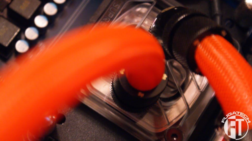
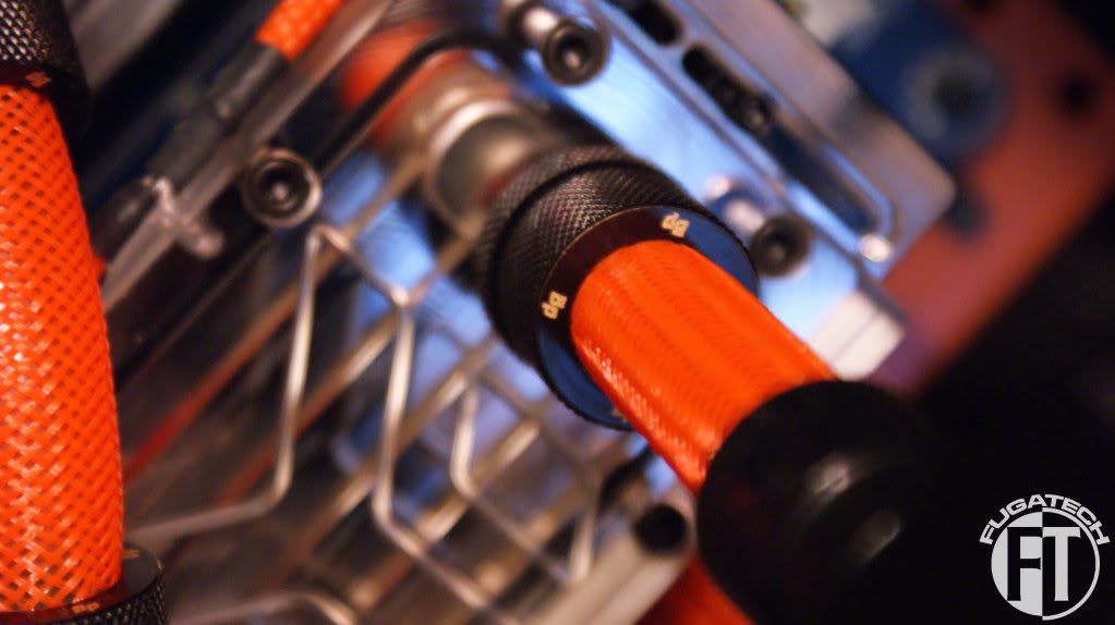
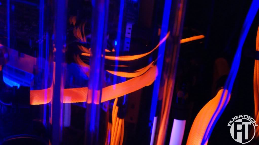
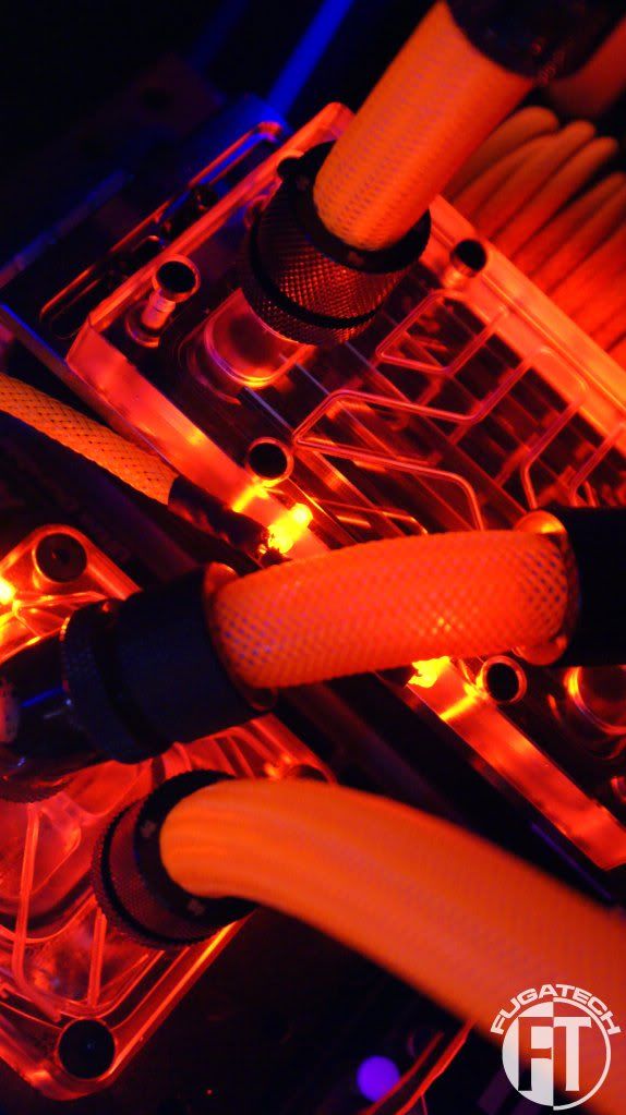
I thought it would be fun to sleeve all of my tubing. Here are some of the early results.
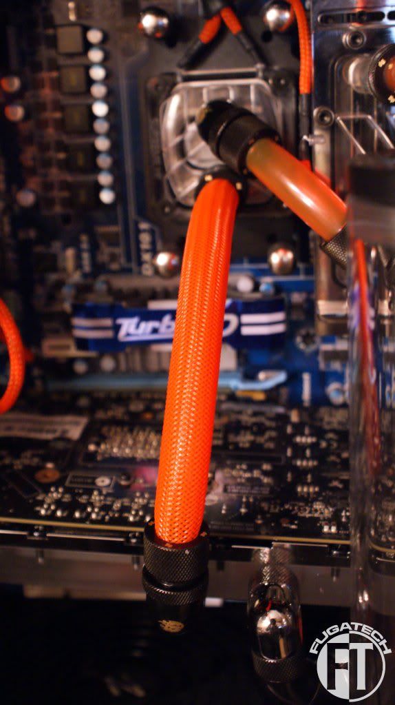
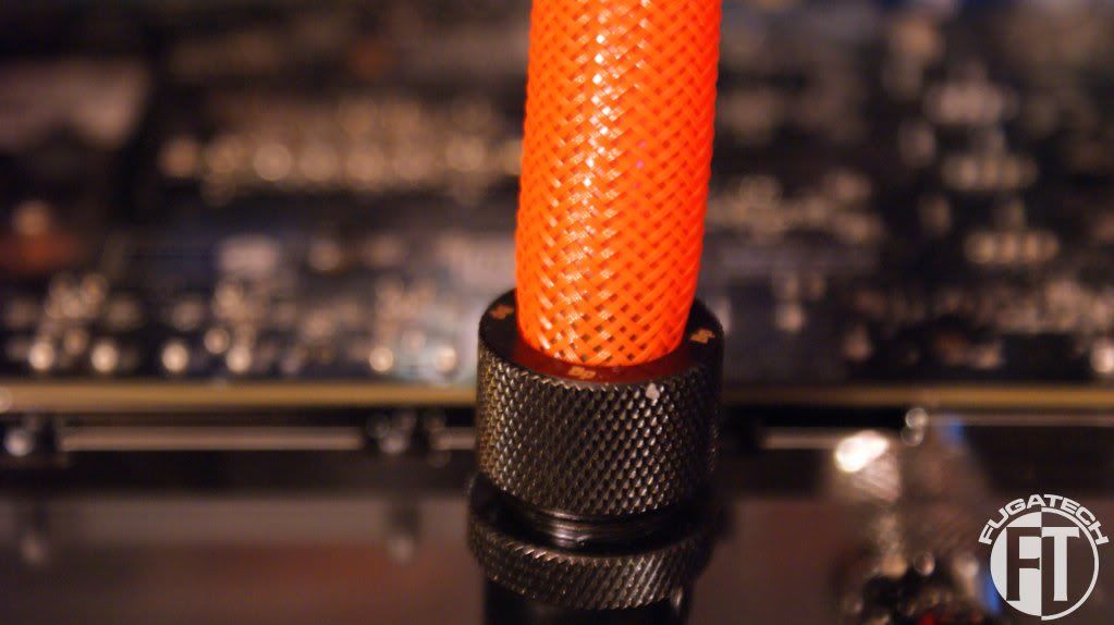
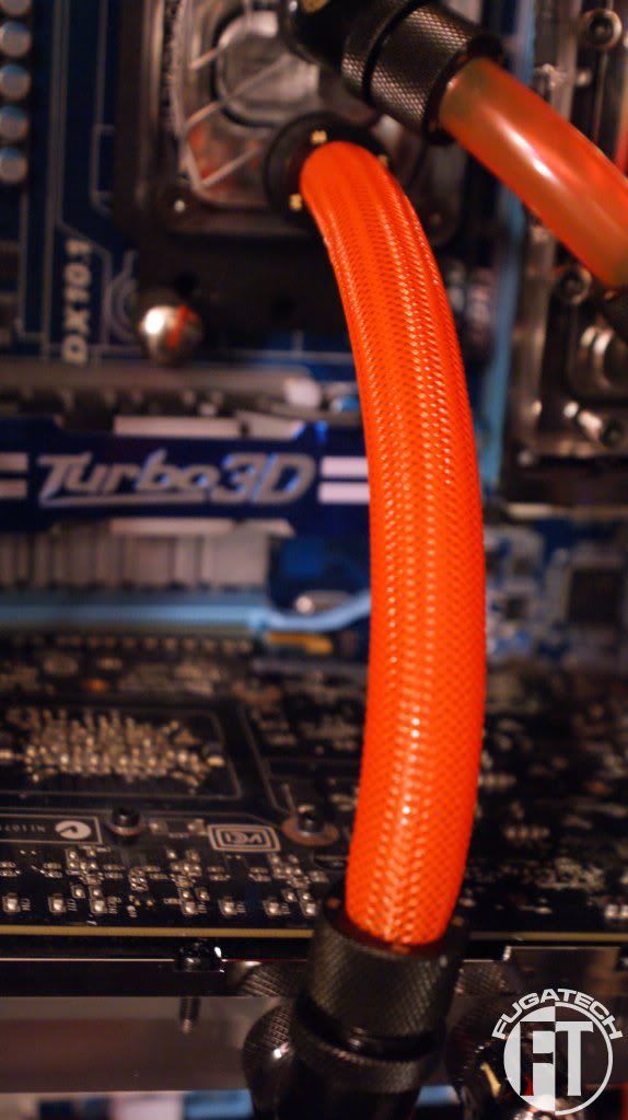
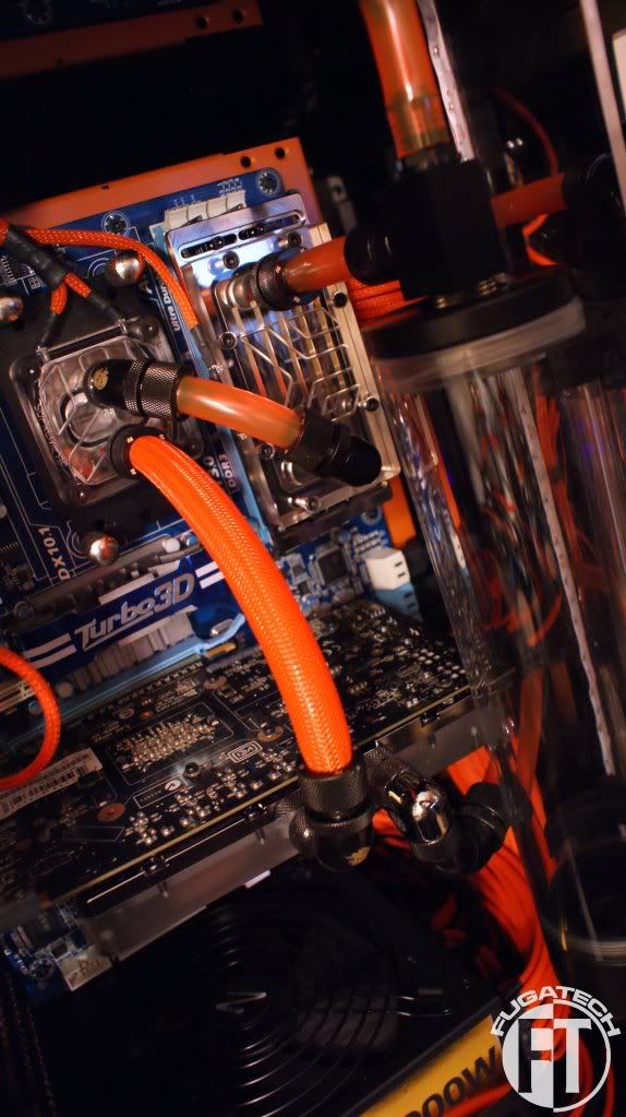
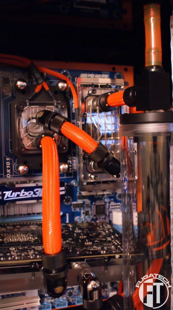

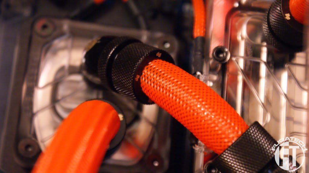
This is my favorite pic for some reason.
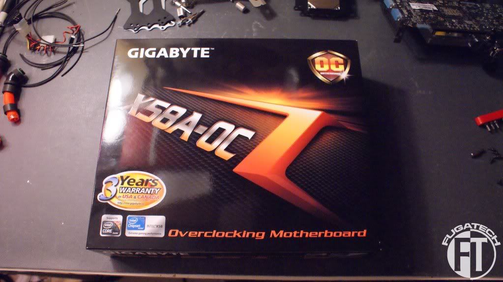
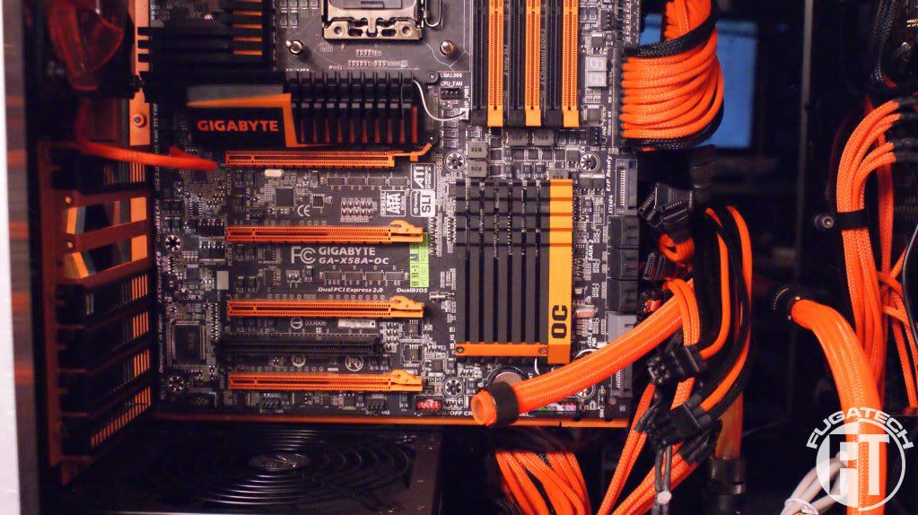
I'm happy to announce that I finally scored the Gigabyte X58 OC mobo. The only downside is that I have to buy new RAM and CPU but its so worth it to have a matching mobo.
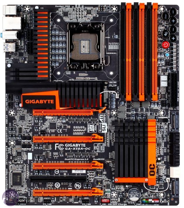
I'm looking at an i7 920 and 6GB of Corsair Dominator RAM. Hopefully this weekend I can cut and mount the font LCD display.
Cheers till next time!
This is my favorite pic for some reason.
I'm happy to announce that I finally scored the Gigabyte X58 OC mobo. The only downside is that I have to buy new RAM and CPU but its so worth it to have a matching mobo.
I'm looking at an i7 920 and 6GB of Corsair Dominator RAM. Hopefully this weekend I can cut and mount the font LCD display.
Cheers till next time!
omegatotal
Gawd
- Joined
- Mar 15, 2002
- Messages
- 672
great colors on the board, too bad the board is focus more specifically on over clockers and multi-gpu than using good components, $299 and having lower end realtek audio and a realtek lan chip is sad :-(
It will definitely look awesome in the case however!
It will definitely look awesome in the case however!
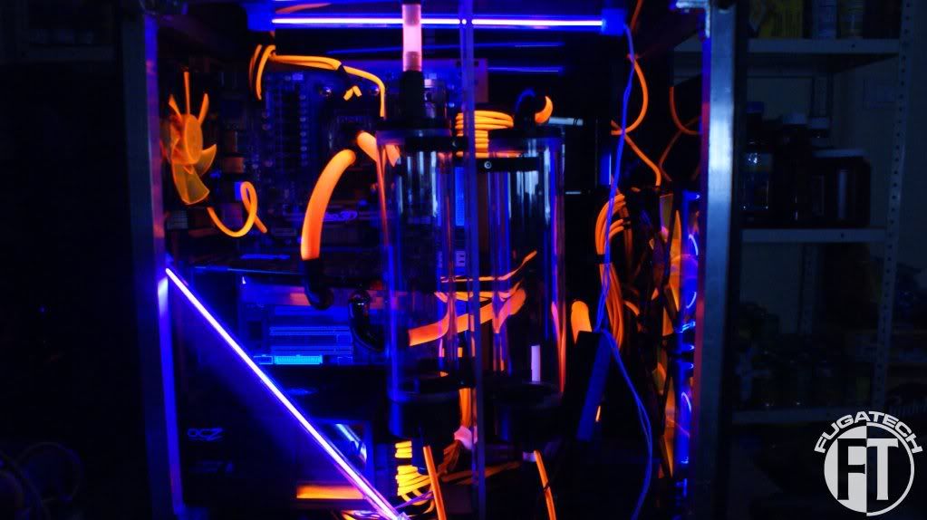
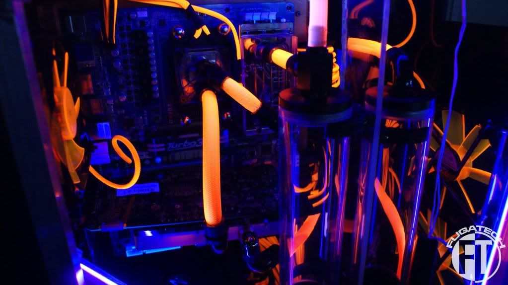
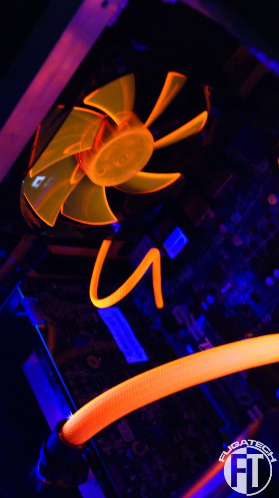
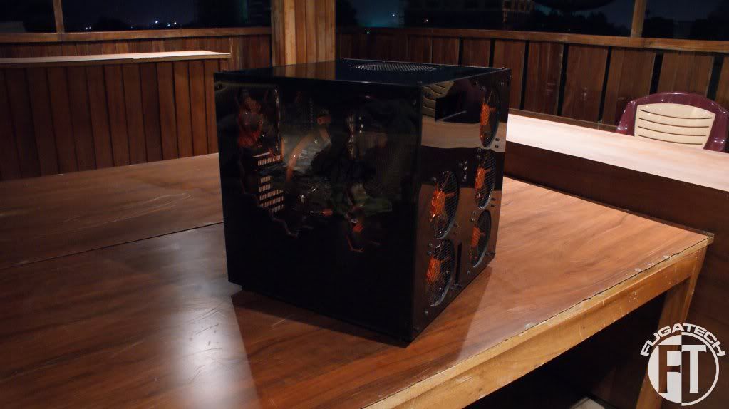
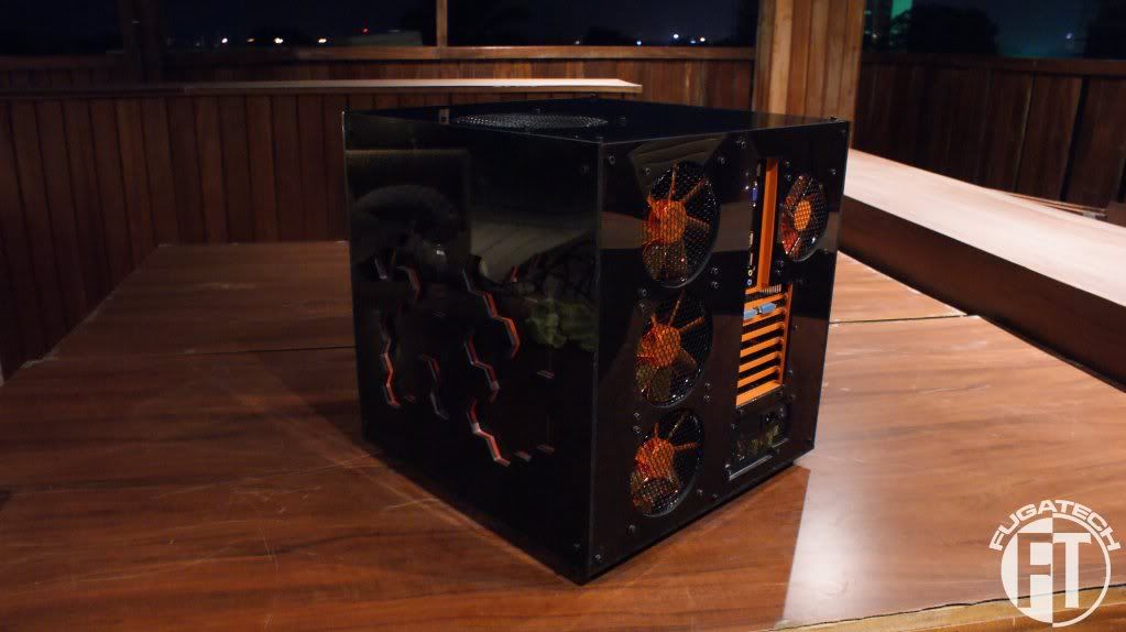
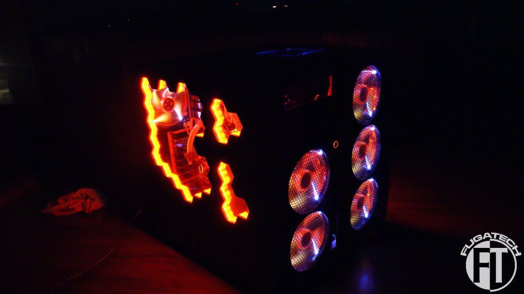
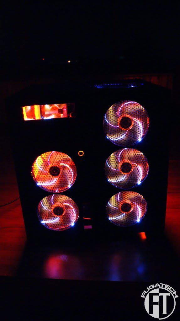
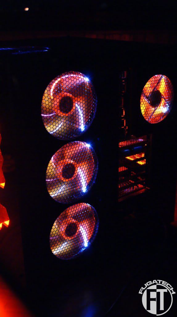
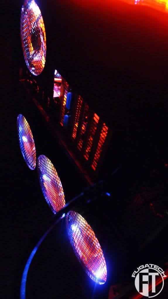
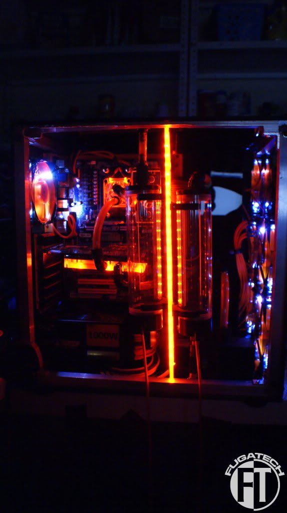
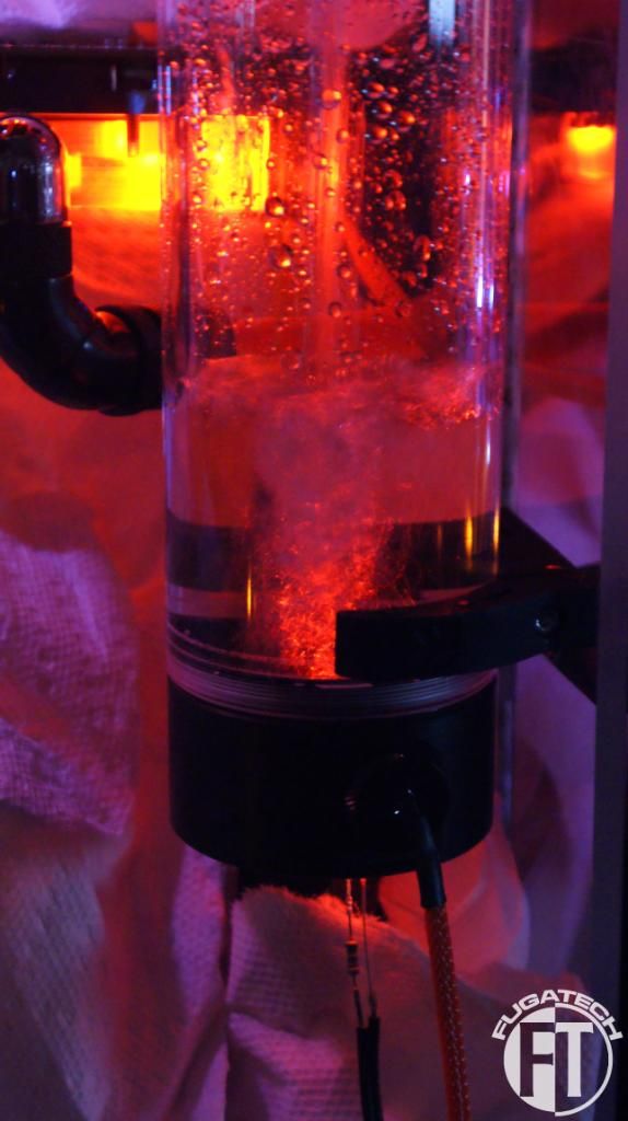
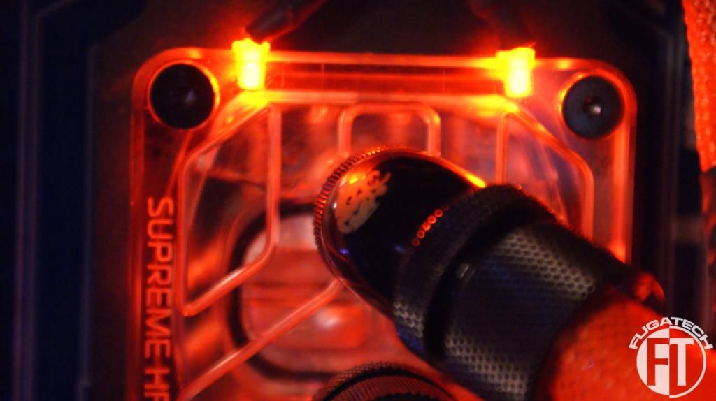
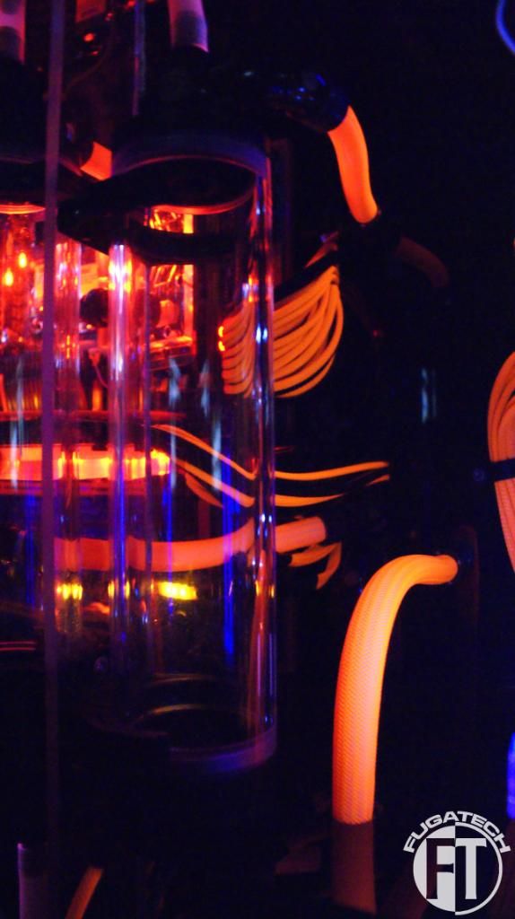
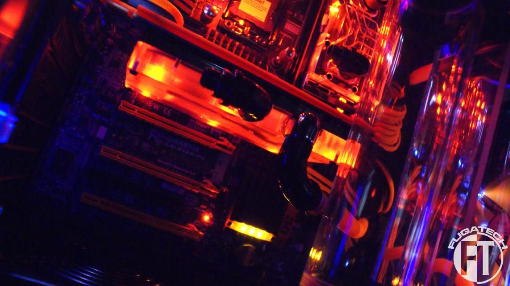
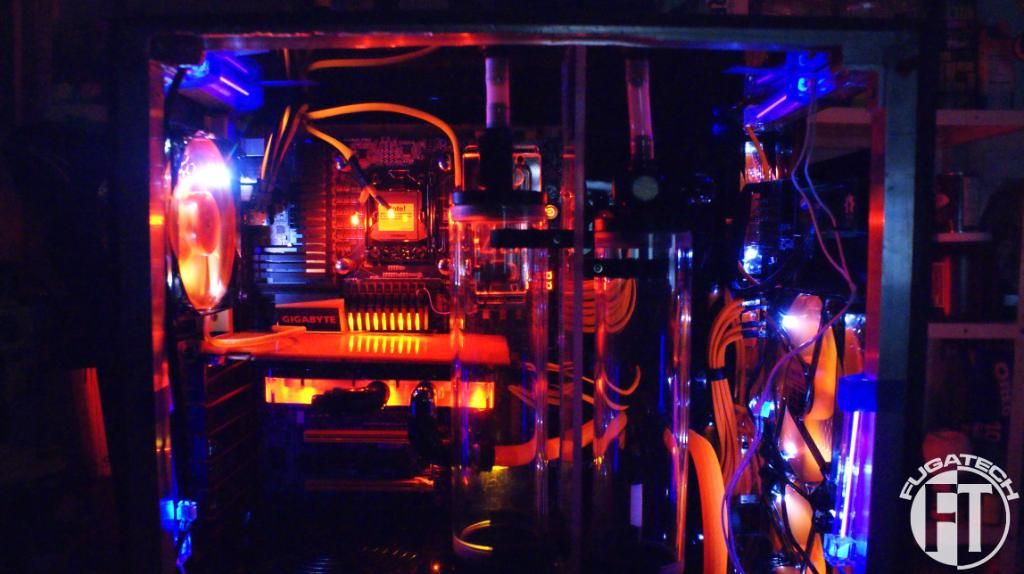
I connected the WB LEDs now and put power to the fans. Here are the results.
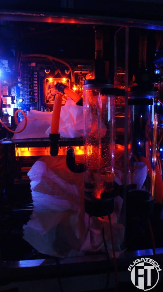
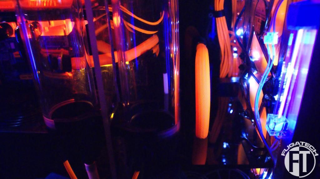
This first set of pictures are with 1 UV Cold Cathode running from front to back on the top of the case and one on the front panel running up and down.
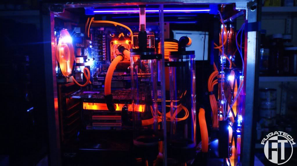
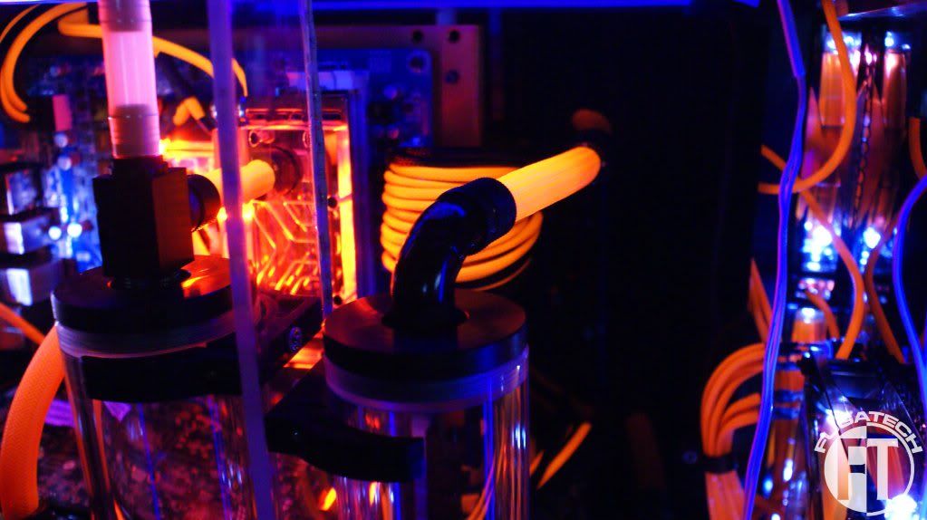
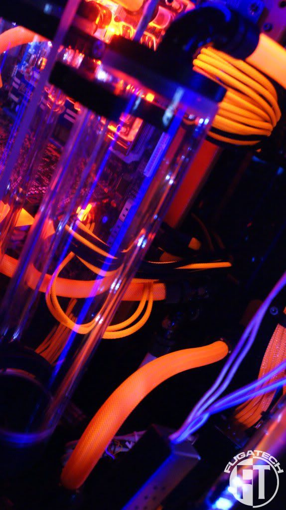
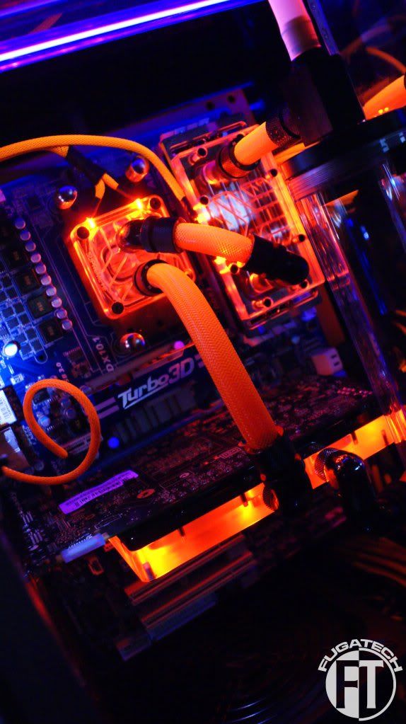
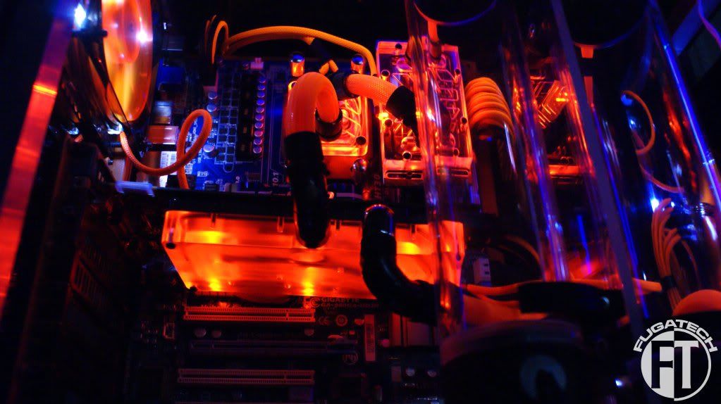
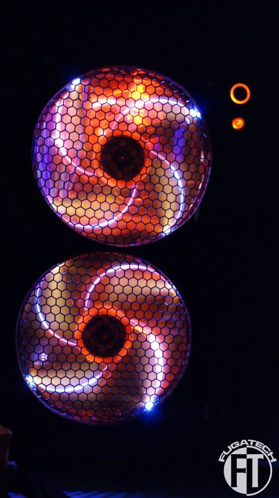
Now these pictures are with both UV Cold Cathodes running the width of the case on the top panel. 1 in front and 1 in back. (That was really hard to explain lol)
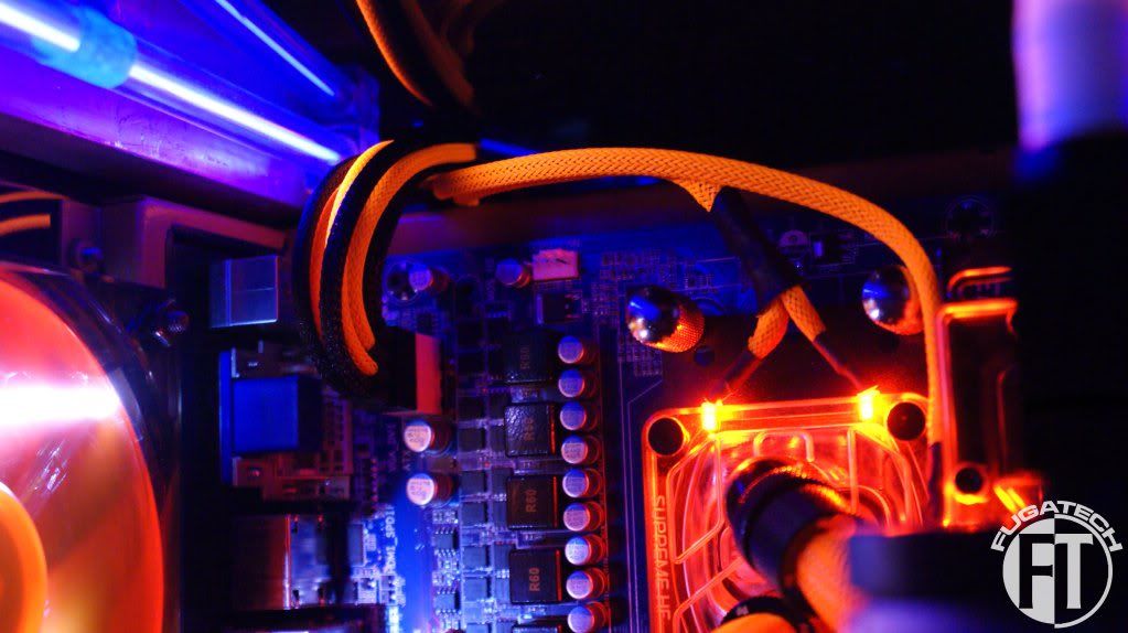
I still have a lot more work to do. Going to make the res LEDs tonight and try to figure out how I'm going to do all the switches for all the different lights.
Cheers till then.
This first set of pictures are with 1 UV Cold Cathode running from front to back on the top of the case and one on the front panel running up and down.
Now these pictures are with both UV Cold Cathodes running the width of the case on the top panel. 1 in front and 1 in back. (That was really hard to explain lol)
I still have a lot more work to do. Going to make the res LEDs tonight and try to figure out how I'm going to do all the switches for all the different lights.
Cheers till then.
- Joined
- May 24, 2006
- Messages
- 17,029
Those UV lights make all the difference in terms of contrast. Nice.
Those UV lights make all the difference in terms of contrast. Nice.
Beautiful work. Love the UV contrasts.
Thanks!
Crazy Chuckster
2[H]4U
- Joined
- Oct 6, 2001
- Messages
- 3,115
Wow, it looks spectacular!
Its voting time! This is the last round of points that goes to the total, its not a "like" contest. You have to register but I know you all will to help out!
Please go here: http://showdown.newmodcity.com/final-round/#comment-59 and vote for my mod in the Scratch Build category.
Thanks!
Please go here: http://showdown.newmodcity.com/final-round/#comment-59 and vote for my mod in the Scratch Build category.
Thanks!
DenverBarr
Limp Gawd
- Joined
- Sep 5, 2011
- Messages
- 211
Absolutley sick love the colours
I wish my WHS looked this cool. It's just a crap Dell.
Hahaha. You can mod anything my friend.
One of the best lit cases I have seen!
You really went for the whole picture, sweet !!!
Thanks!
Absolutley sick love the colours
Thanks! I'm really happy with how they turned out.
My goodness where has the time gone??? Where to start??
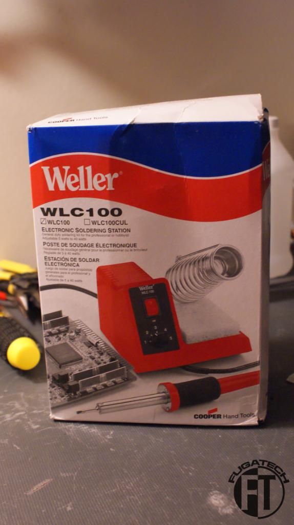
Lets start with some goodies!!
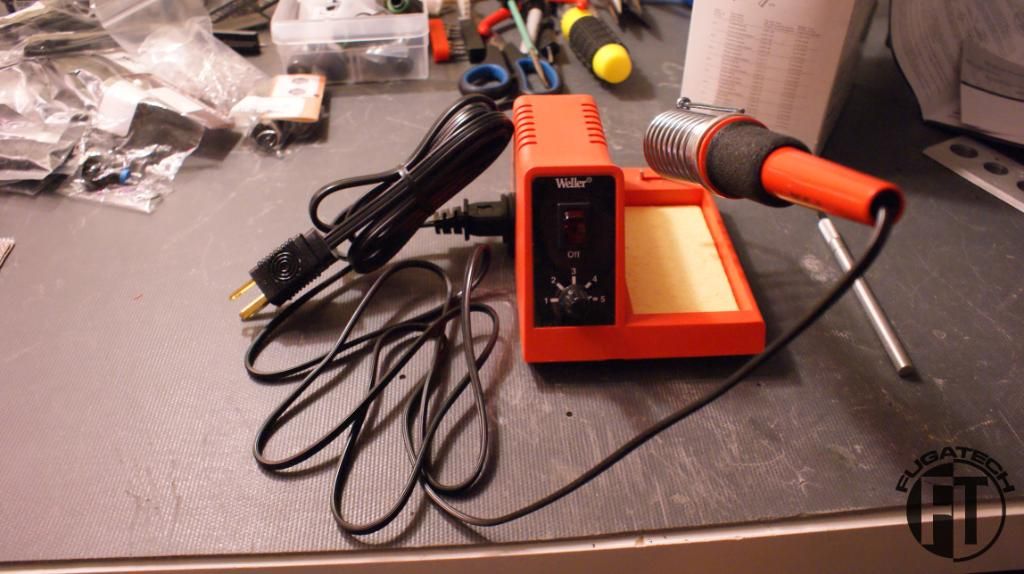
Got a new soldering station. I like it but I need to buy some different tips for different jobs.
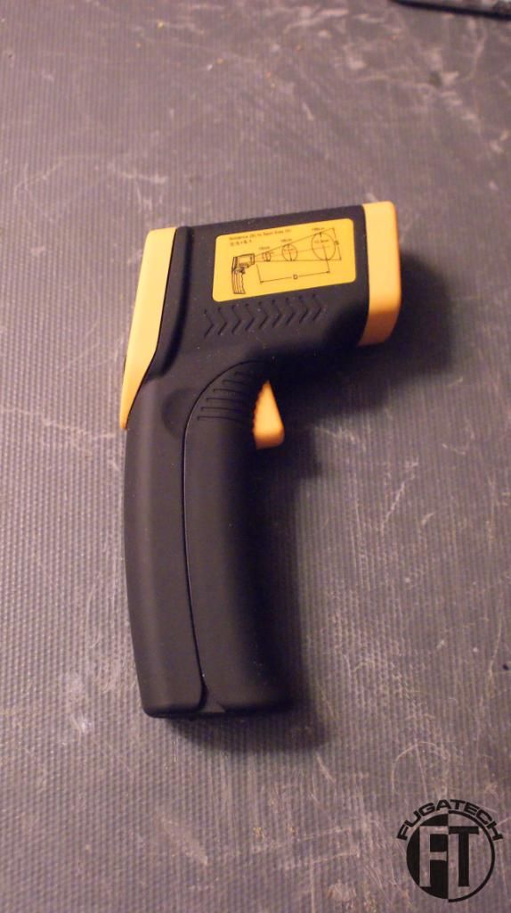
A spot temp sensor that I got for Christmas. The best tool for identifying dead spots/hot spots in your case.
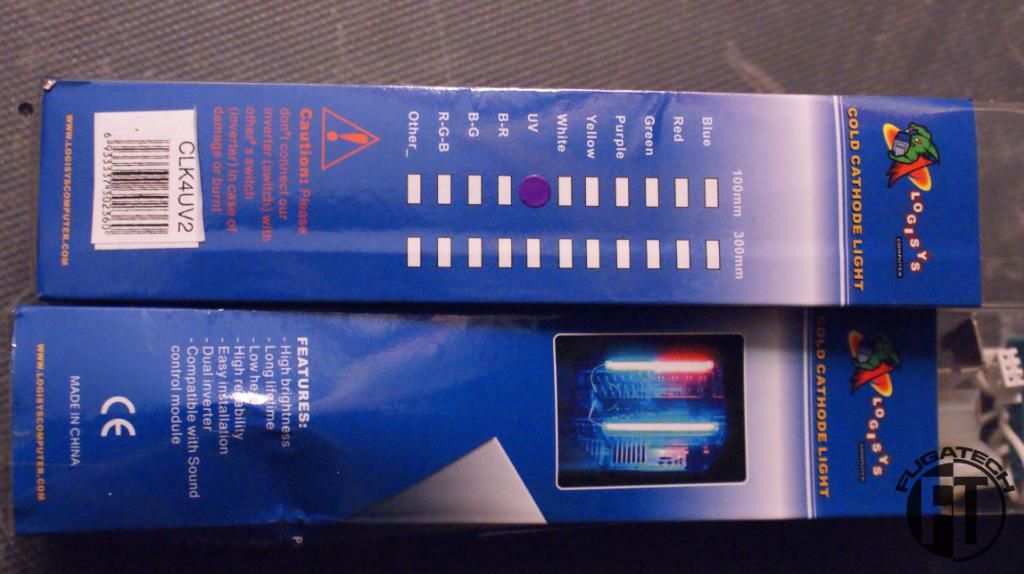
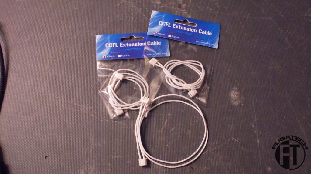
4" UV Cold Cathodes + extensions
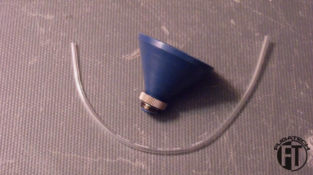
An awesome threaded funnel with air tube
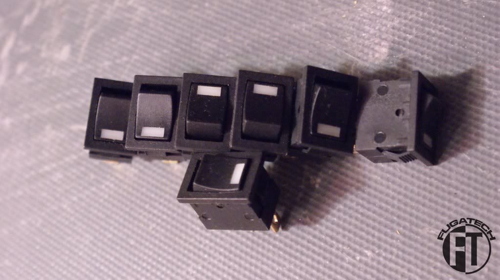
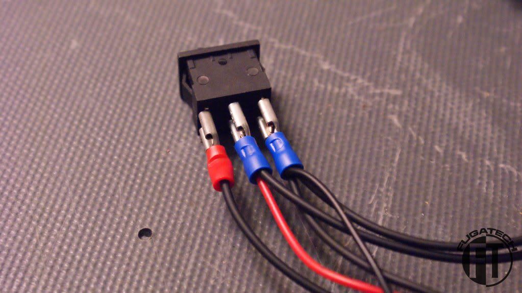
Rocker switches for turning on and off all the lights.
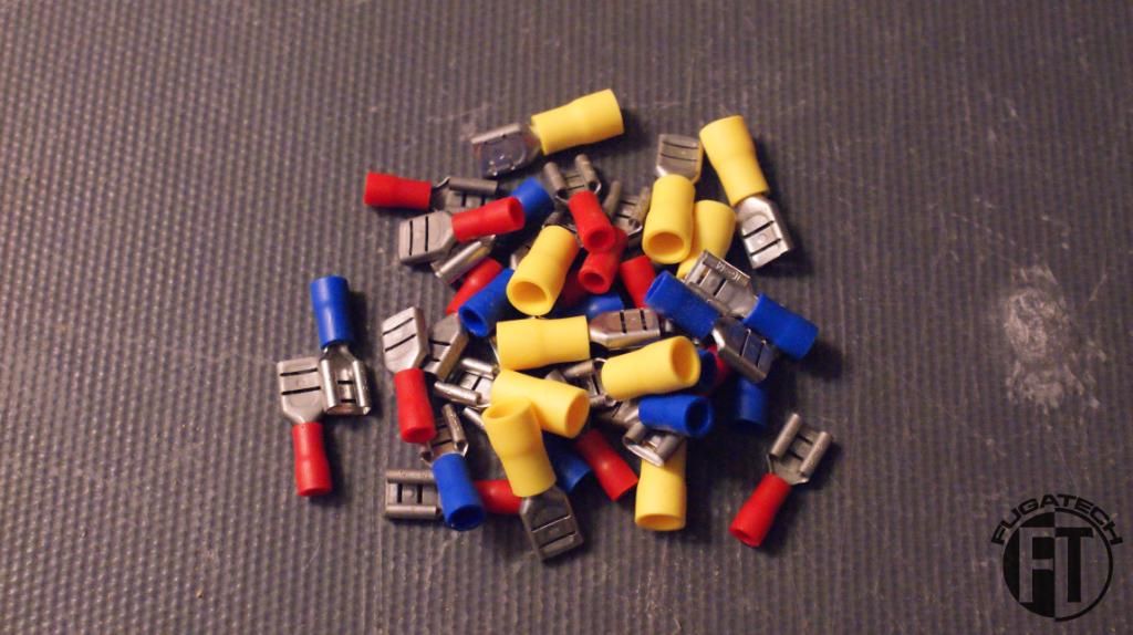
A bunch of terminals for the rocker switches
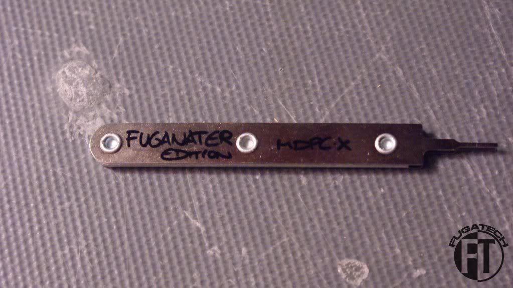
MDPC ATX pin remover
Gigabyte GA-X58A-OC mobo!!!!
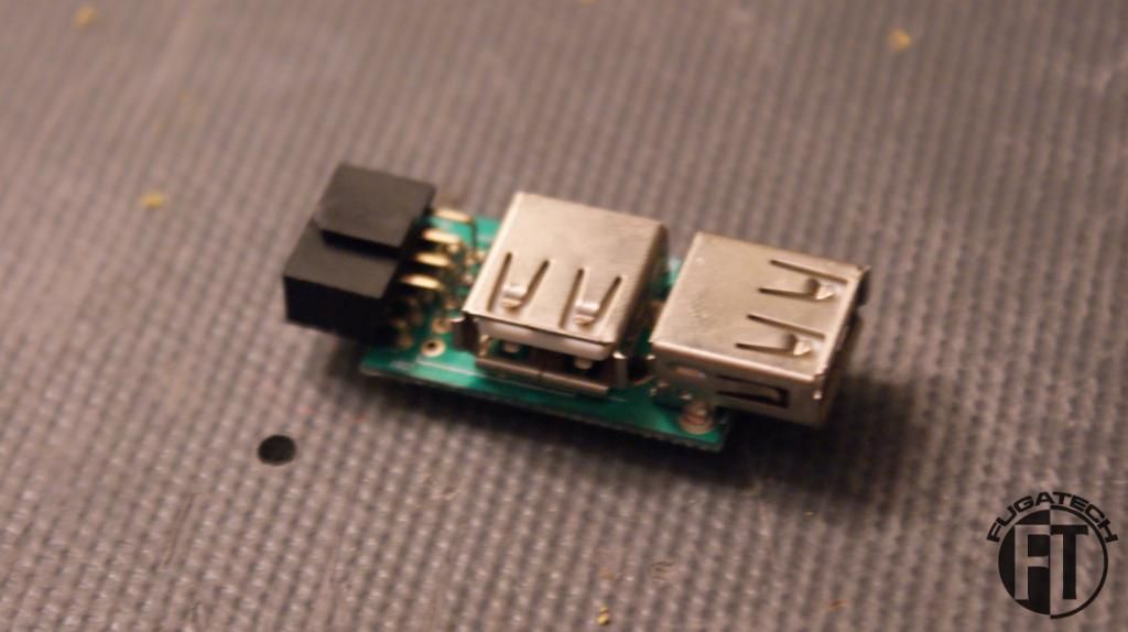
Internal USB plugs
On to the modding!!
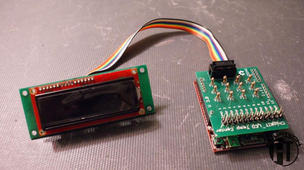
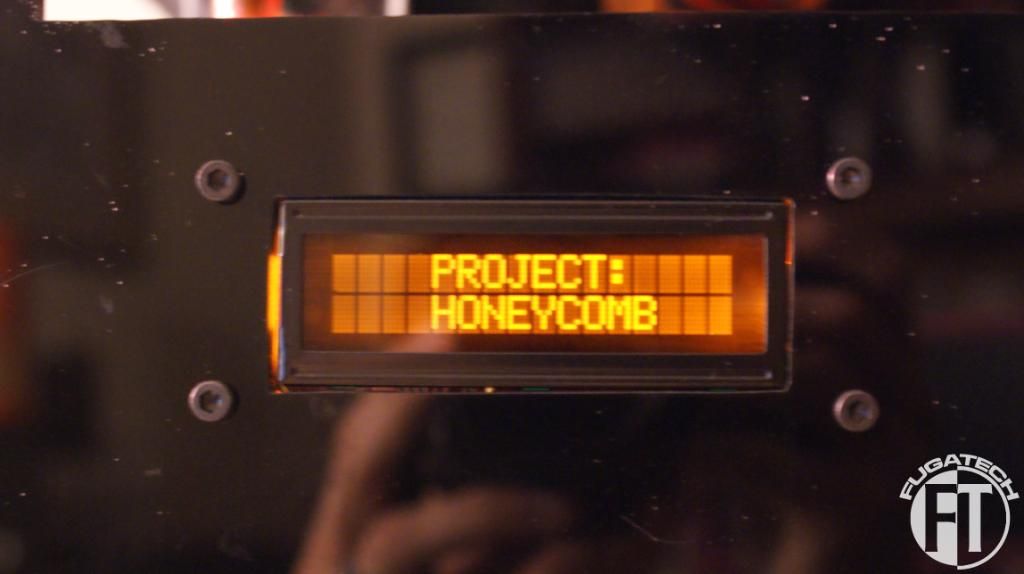
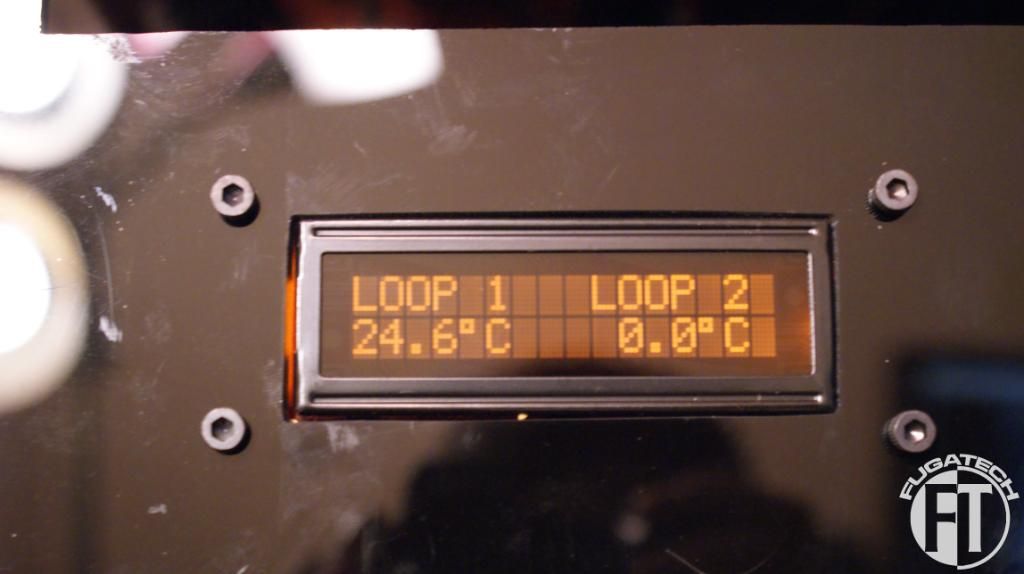
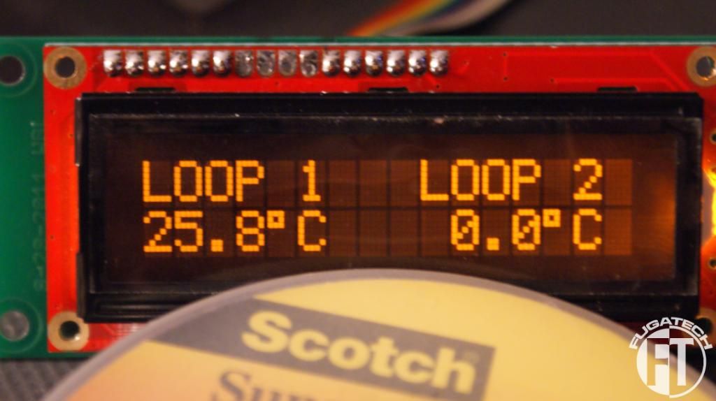
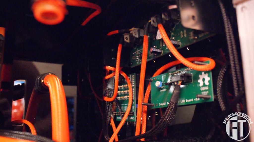
I contracted Will from TBCS to make me an LCD temp sensor setup for this mod. Its 2 pieces, the LCD and control board. It can display up to 12 different temps! I'm very very happy with it.
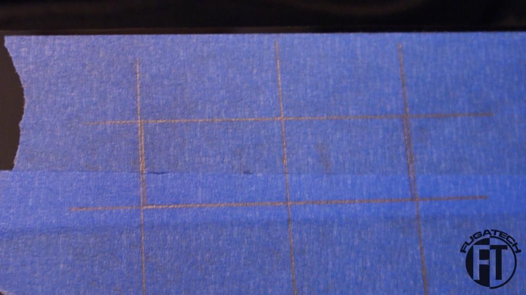
Here is the front all taped up and sketched out. Time to drill and cut!
And here is how it looks installed.
Thanks Will for all your help!
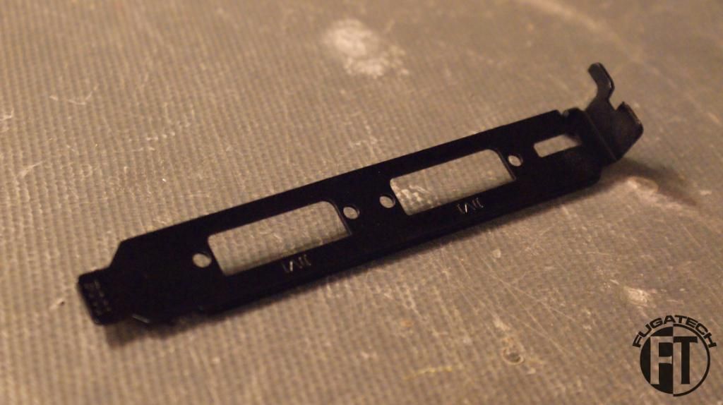
Now for the GPU. I got a single PCI bracket for it since its WC'd.
I'm a huge fan now of making backplates for all my GPUs. Measured.
Here it is mounted to the card and installed in the case.
It didn't come out very good because Bitspower uses different sized screws than DD does so my longer screws didn't fit. I may remake it later without drilling any holes in it.
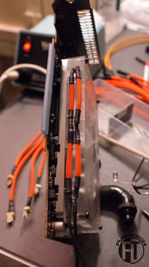
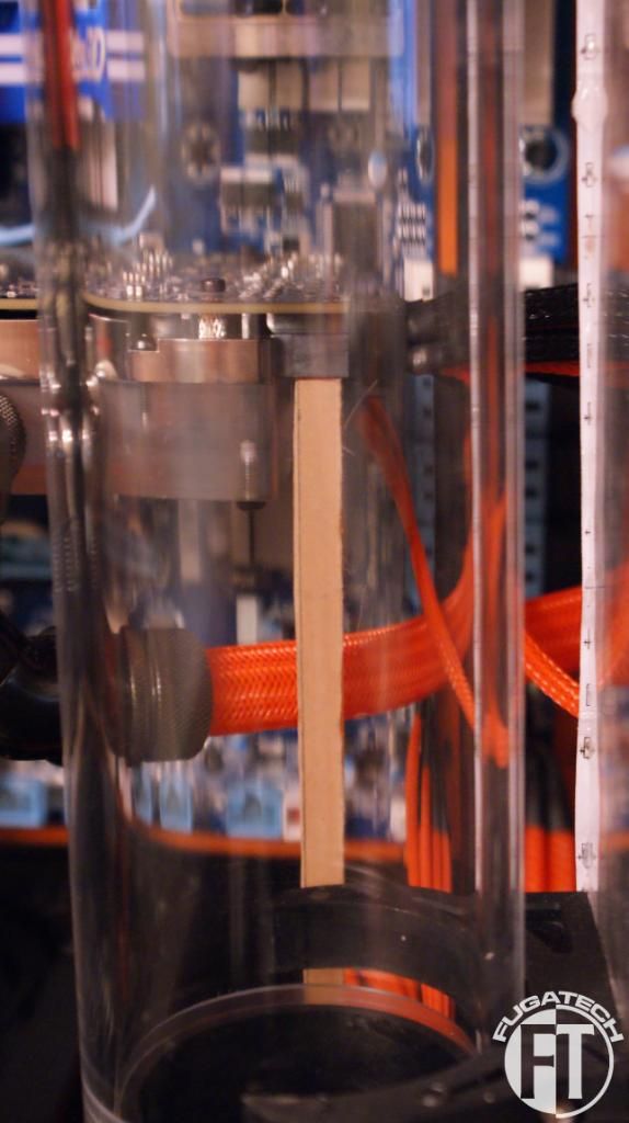
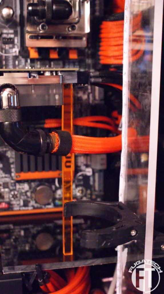
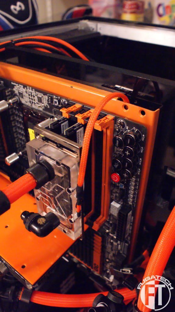
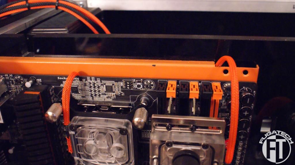
Everyone noticed how my GPU was sagging because of the Bitspower WB. Here is my fix. A 1/4" x 1/4" piece of orange acrylic cut to height. (the paper was still on when I took these)
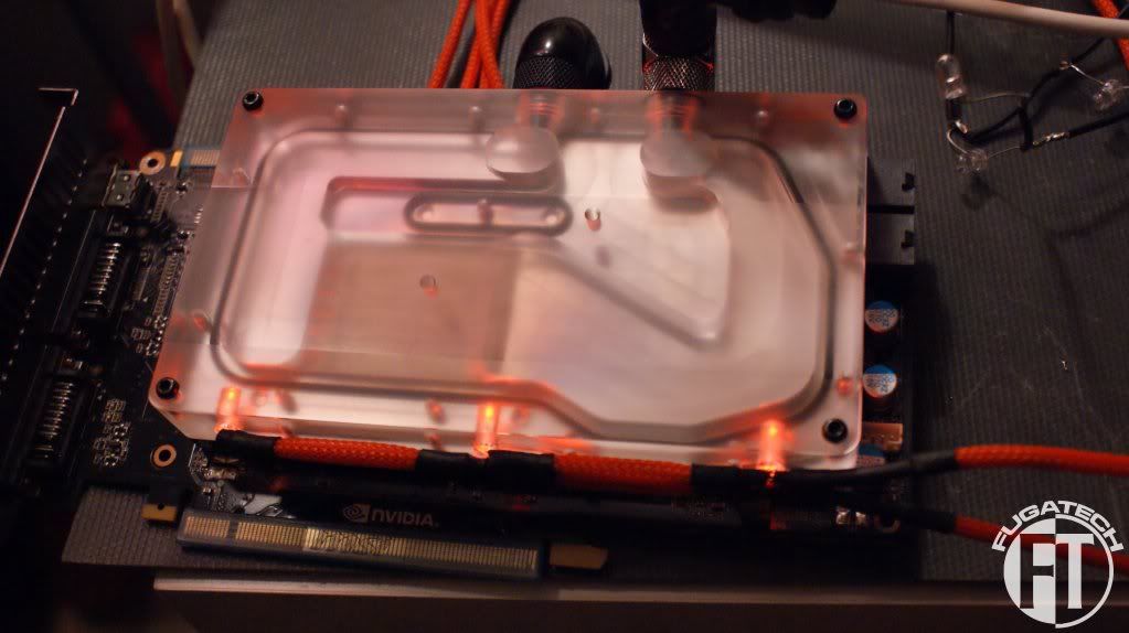
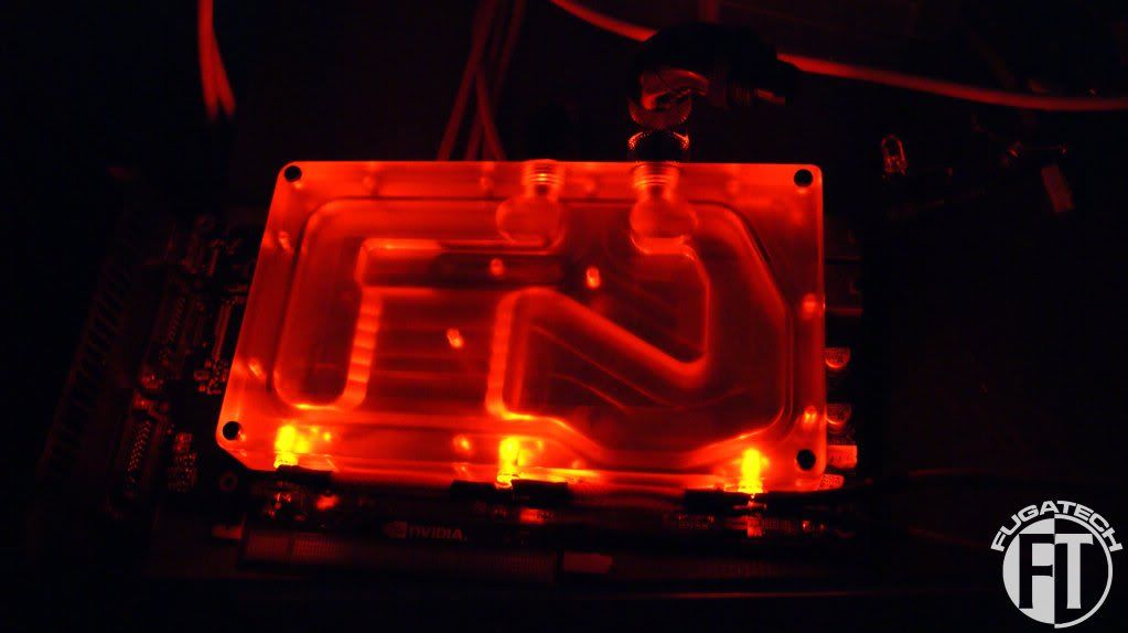
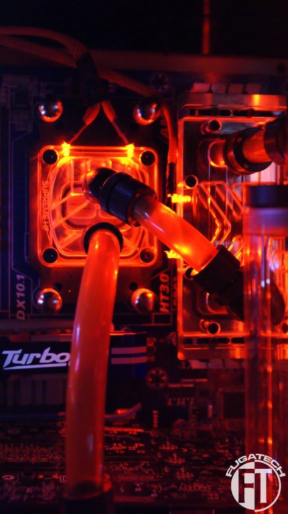
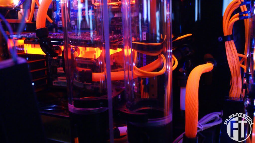
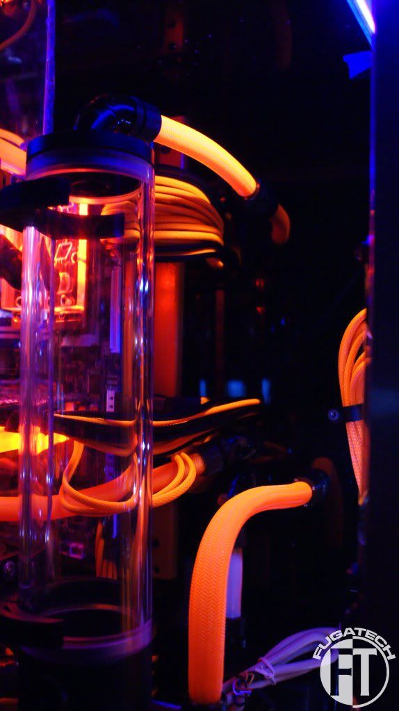
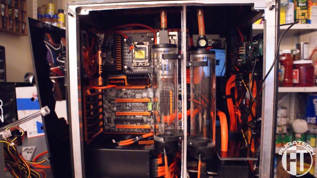
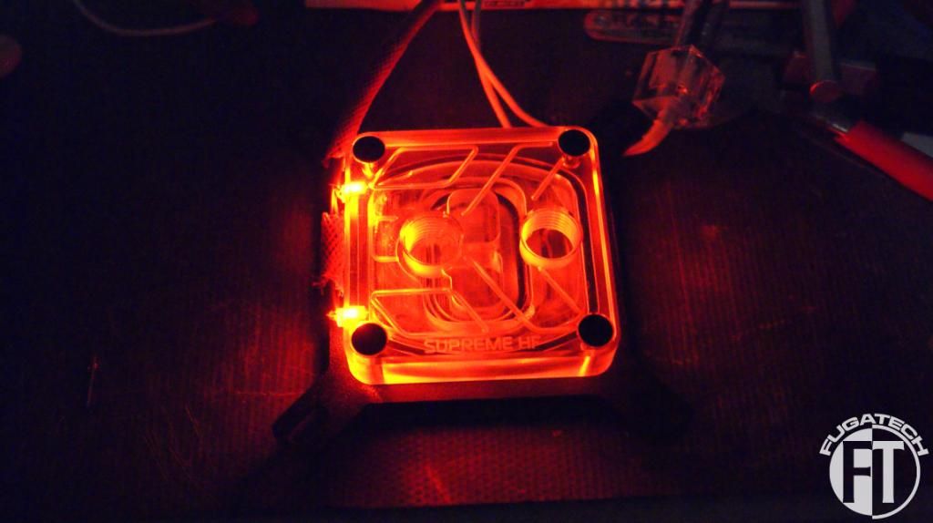
After awhile I just HAD to put water in this to see how it ran.
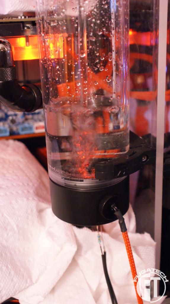
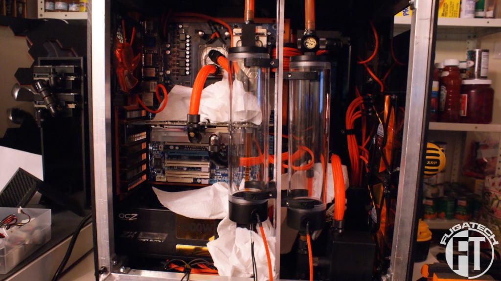
No load. No OS. Just running.
I noticed an air bubble in my CPU block.... I need to figure out how to get rid of that.
Since I got that awesome OC board I had to get that slapped in ASAP! So out with the old.
And in with the new.

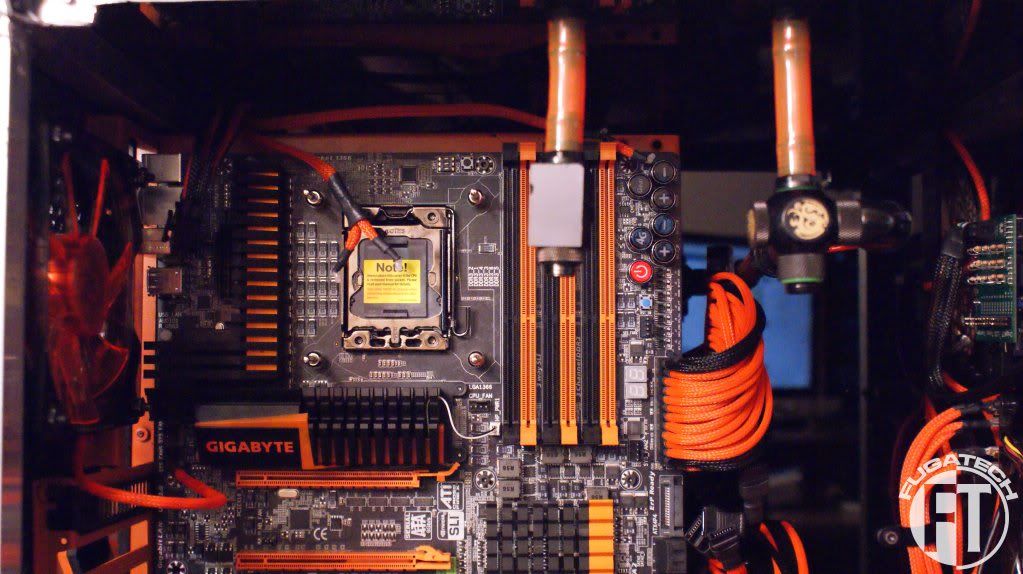
The ATX connector is in a different spot so it looks a bit off.
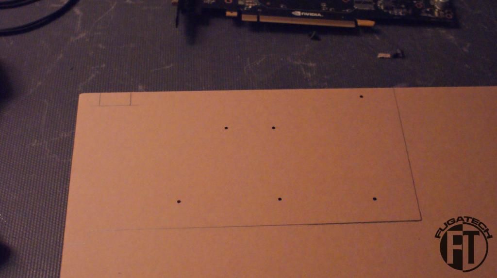
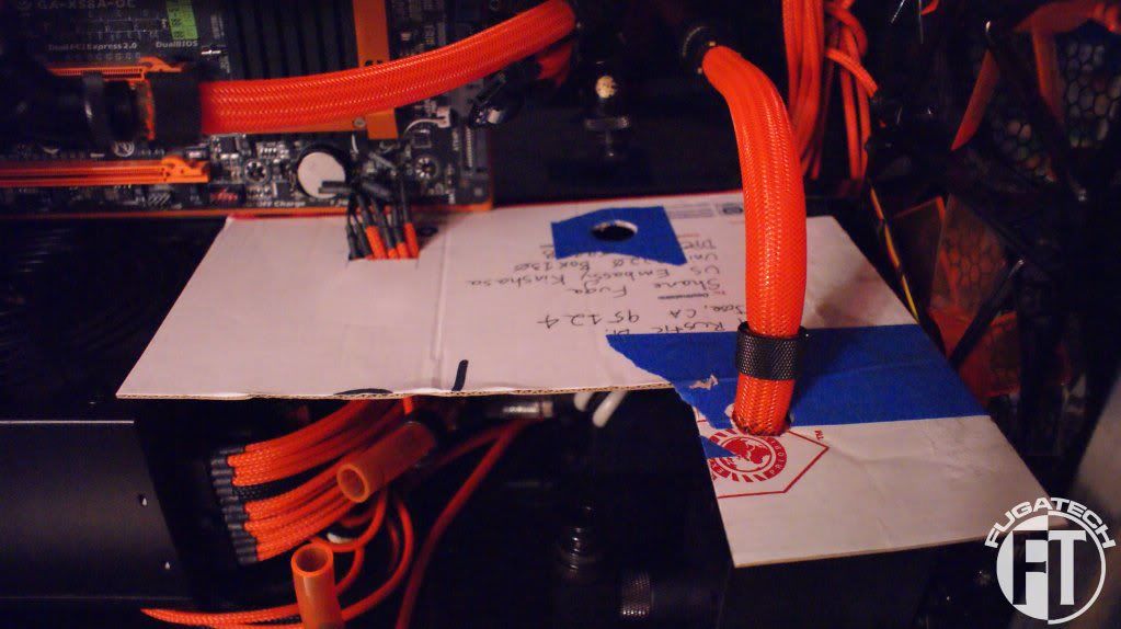
I wanted to make a midplate to hide all the wires. A PSU shroud just won't be possible any more. I started with cardboard.
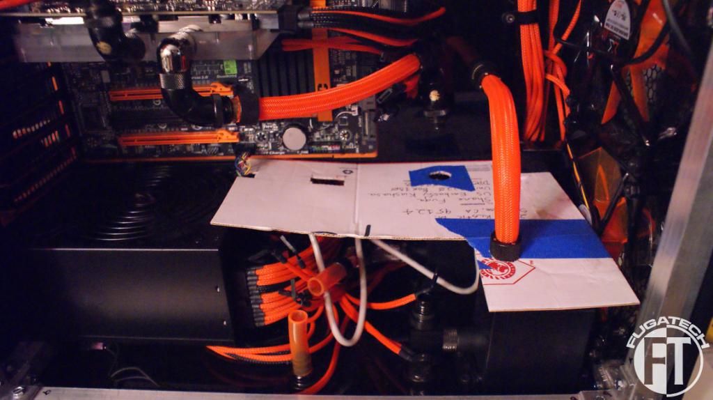
Have to make sure the res support bracket can still fit.
It only goes back so far because that's the biggest I could go unless I buy another sheet of acrylic. I'm debating it but then that means I would have to flip my PSU and drill another hole... decisions decisions...
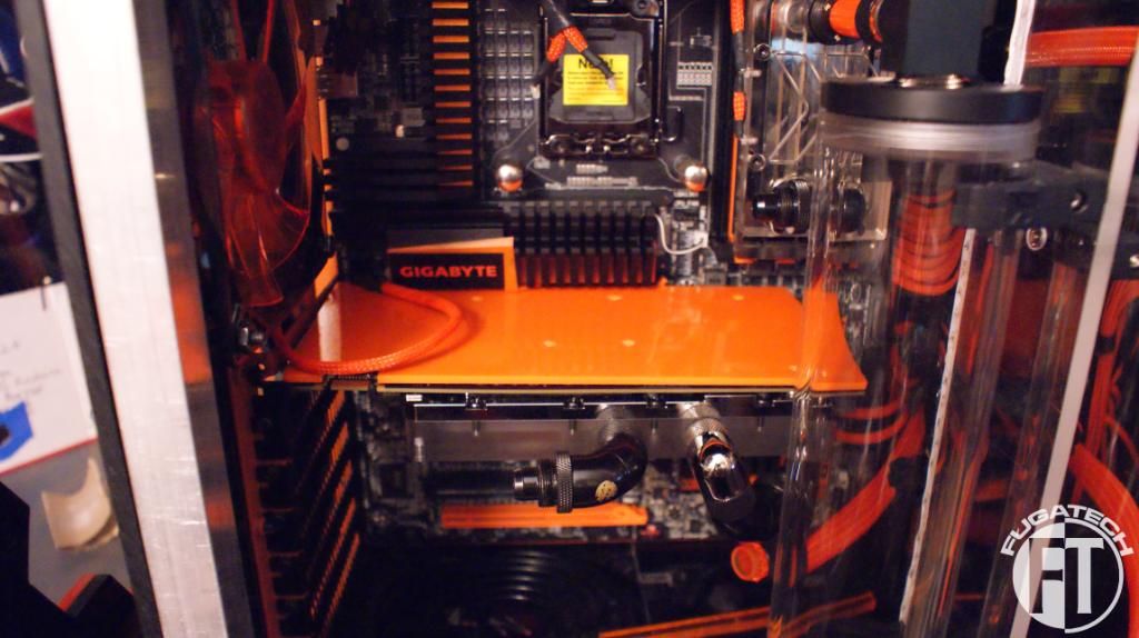
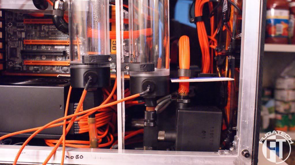
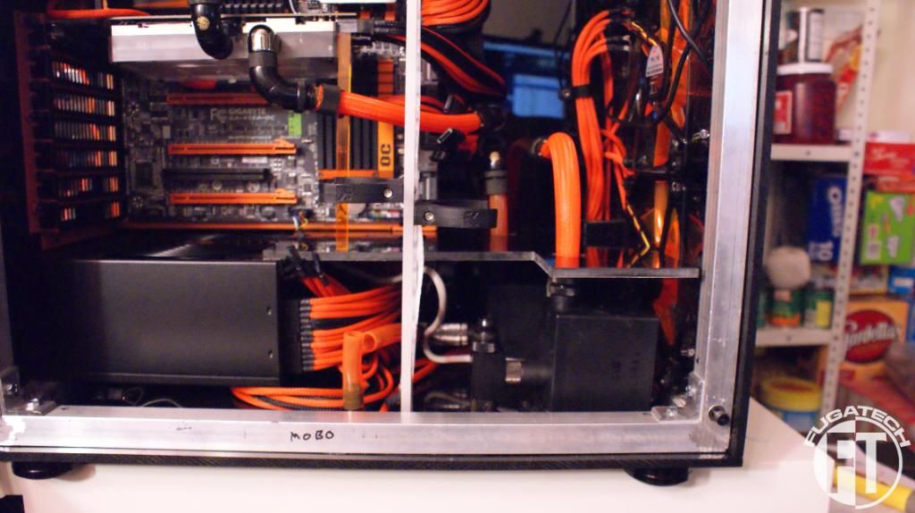
Well I cut and installed the midplate. Here is how it looks.
Since it goes under the GPU I had to shorten the brace. This works out great because it puts pressure on the corner that needs held down and I don't need to screw or glue the midplate into place.
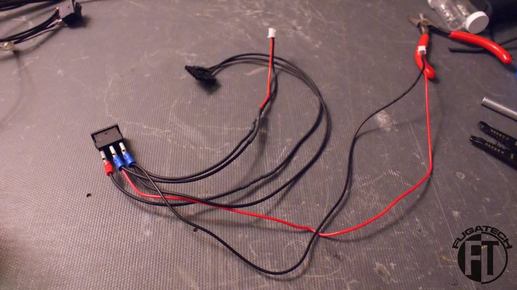
Since I never used rocker switches I had to experiment to get them to work.
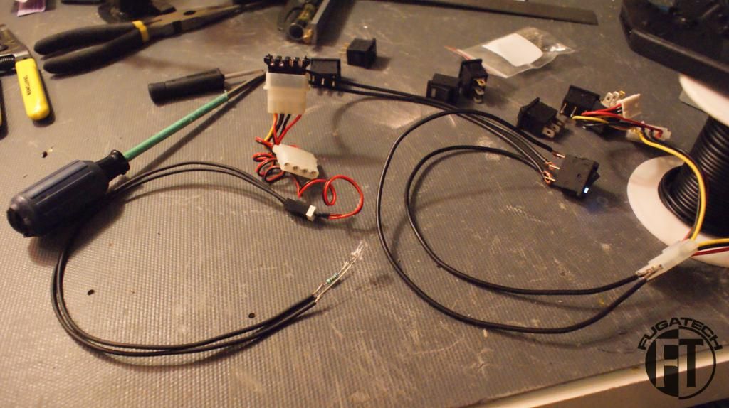
This was great because I was able to cut and rewire my cold cathodes to use one new rocker switch that will be mounted in the back of the case. That will be in my next update.
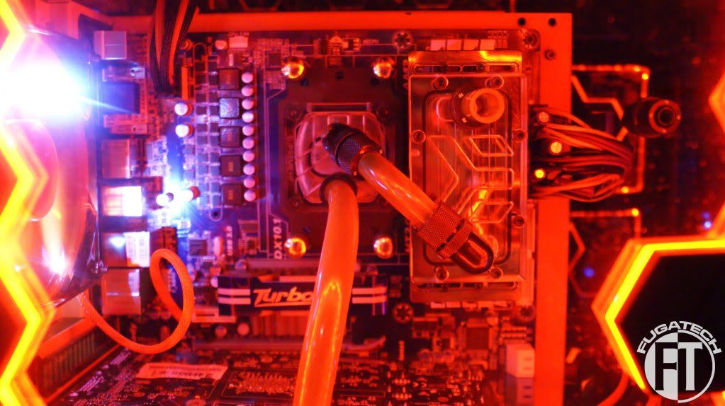
And lastly I installed the 4x 4" UV cold cathodes to see how it all looked.
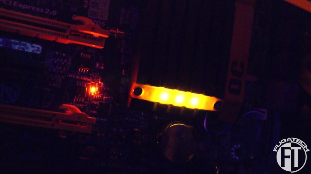
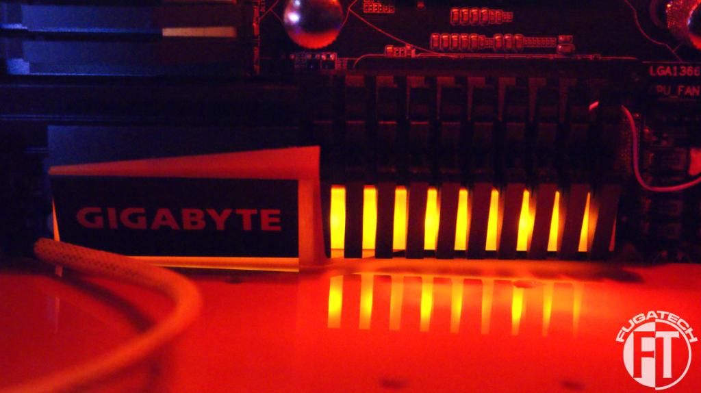
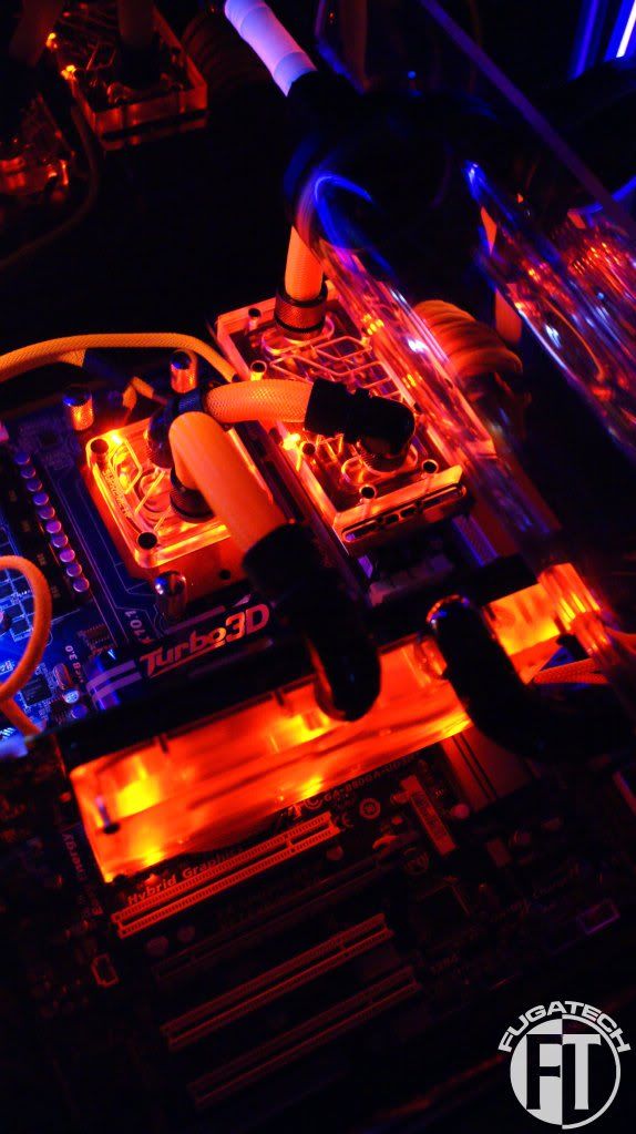
I love how the mobo has some lighting in it already. Fits in PERFECTLY!!
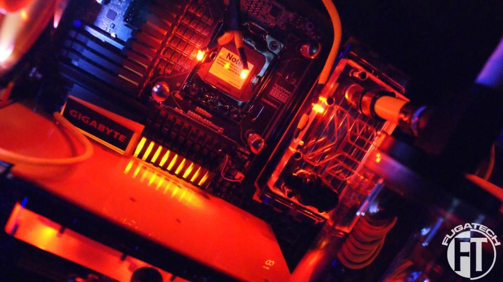
That's it for today. I'm sorry this update is so big. December has been crazy for us. I'll do my best to keep updates smaller and more frequent.
Cheers till next time.
Lets start with some goodies!!
Got a new soldering station. I like it but I need to buy some different tips for different jobs.
A spot temp sensor that I got for Christmas. The best tool for identifying dead spots/hot spots in your case.
4" UV Cold Cathodes + extensions
An awesome threaded funnel with air tube
Rocker switches for turning on and off all the lights.
A bunch of terminals for the rocker switches
MDPC ATX pin remover
Gigabyte GA-X58A-OC mobo!!!!
Internal USB plugs
On to the modding!!
I contracted Will from TBCS to make me an LCD temp sensor setup for this mod. Its 2 pieces, the LCD and control board. It can display up to 12 different temps! I'm very very happy with it.
Here is the front all taped up and sketched out. Time to drill and cut!
And here is how it looks installed.
Thanks Will for all your help!
Now for the GPU. I got a single PCI bracket for it since its WC'd.
I'm a huge fan now of making backplates for all my GPUs. Measured.
Here it is mounted to the card and installed in the case.
It didn't come out very good because Bitspower uses different sized screws than DD does so my longer screws didn't fit. I may remake it later without drilling any holes in it.
Everyone noticed how my GPU was sagging because of the Bitspower WB. Here is my fix. A 1/4" x 1/4" piece of orange acrylic cut to height. (the paper was still on when I took these)
After awhile I just HAD to put water in this to see how it ran.
No load. No OS. Just running.
I noticed an air bubble in my CPU block.... I need to figure out how to get rid of that.
Since I got that awesome OC board I had to get that slapped in ASAP! So out with the old.
And in with the new.
The ATX connector is in a different spot so it looks a bit off.
I wanted to make a midplate to hide all the wires. A PSU shroud just won't be possible any more. I started with cardboard.
Have to make sure the res support bracket can still fit.
It only goes back so far because that's the biggest I could go unless I buy another sheet of acrylic. I'm debating it but then that means I would have to flip my PSU and drill another hole... decisions decisions...
Well I cut and installed the midplate. Here is how it looks.
Since it goes under the GPU I had to shorten the brace. This works out great because it puts pressure on the corner that needs held down and I don't need to screw or glue the midplate into place.
Since I never used rocker switches I had to experiment to get them to work.
This was great because I was able to cut and rewire my cold cathodes to use one new rocker switch that will be mounted in the back of the case. That will be in my next update.
And lastly I installed the 4x 4" UV cold cathodes to see how it all looked.
I love how the mobo has some lighting in it already. Fits in PERFECTLY!!
That's it for today. I'm sorry this update is so big. December has been crazy for us. I'll do my best to keep updates smaller and more frequent.
Cheers till next time.
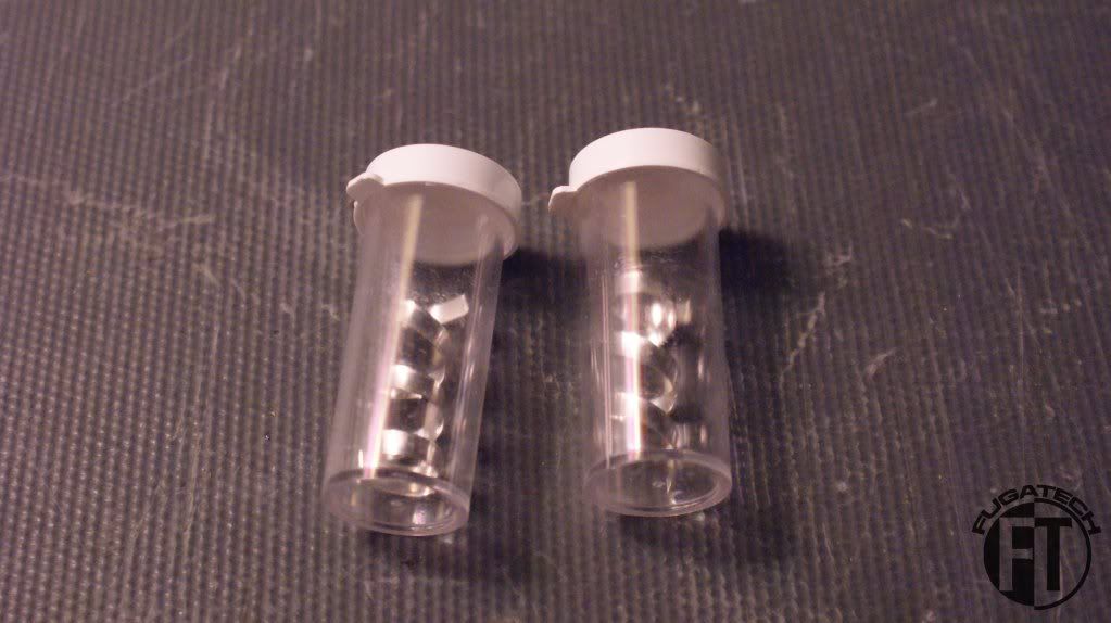
Forgot to say in my last update that I got some Silver Kill Coils for the loops.
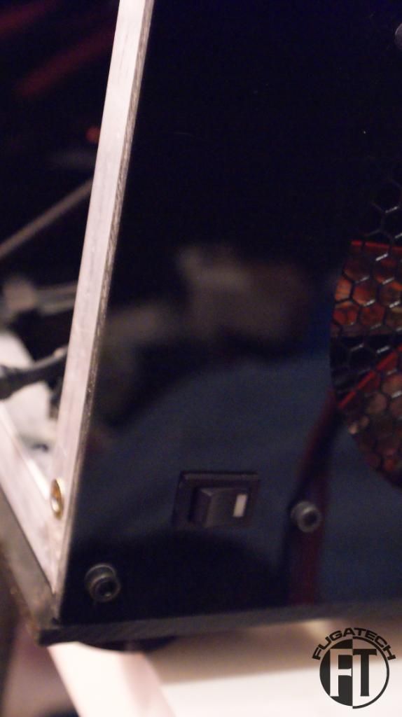
Since I had never used rocker switches before I had to do some testing.
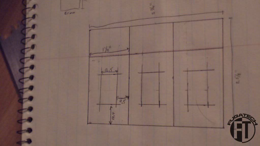
Now how to mount them? I made a sketch so I knew the measurements.
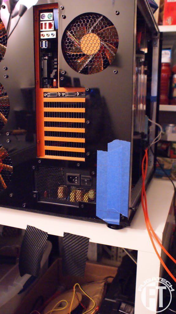
Put on some tape.
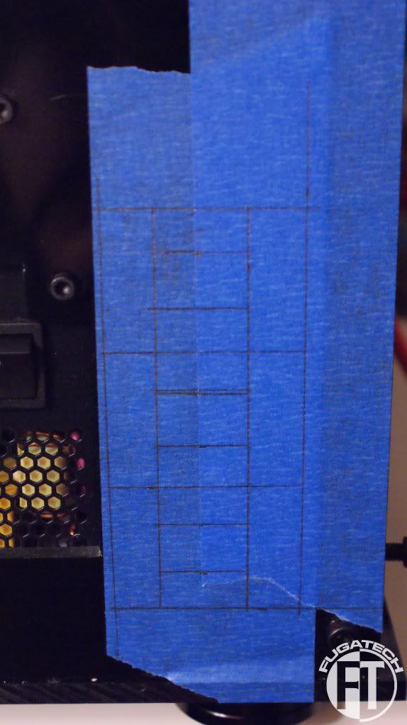
Marked
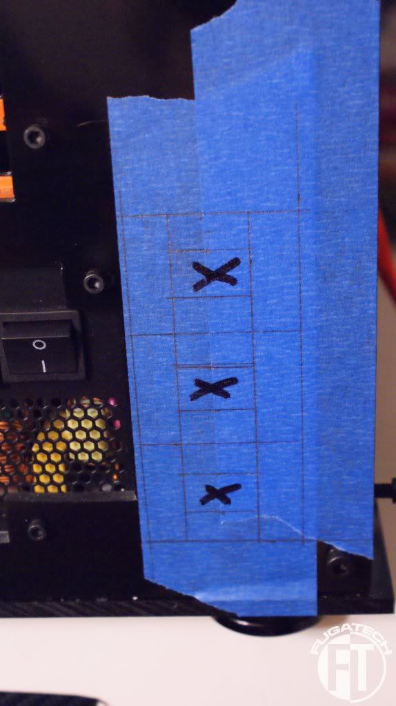
Cut and installed!
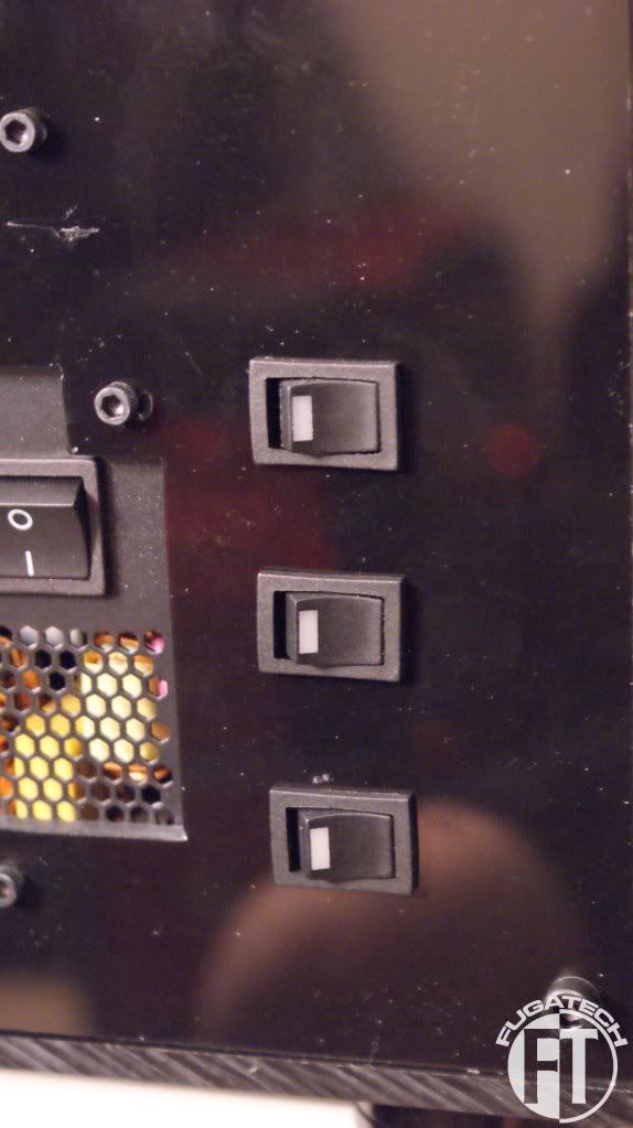
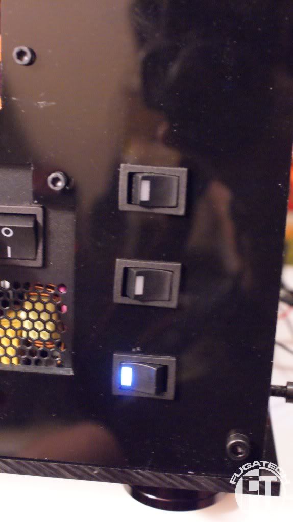
It works!
Inside view.
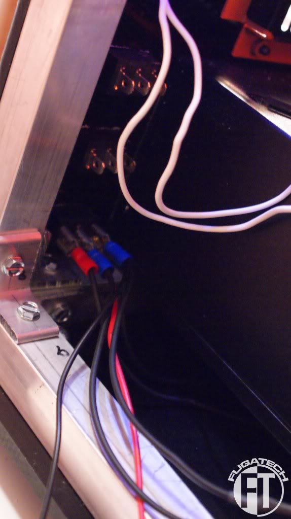
These 3 will control the Mobo door LED, All UV Cold Cathodes on both sides of the case, and the res LEDs.
I put another switch on the HDD side of the case for the HDD door LEDs.
Inside view.
Because I had the CPU block sideways for the AMD chip I had to redo my LEDs.
Next I pulled the top of the case off so it would be easier to work on the next few parts.
I decided I didn't like how the cables looked. They needed to be tied up and hidden better. So I started the process of putting cable ties on.
Looks much much better
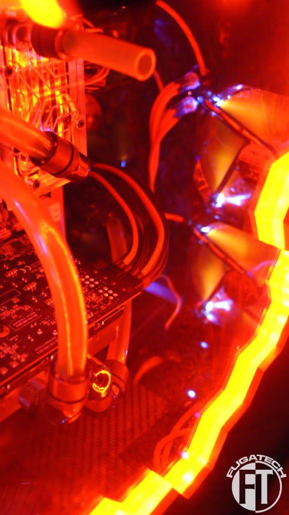
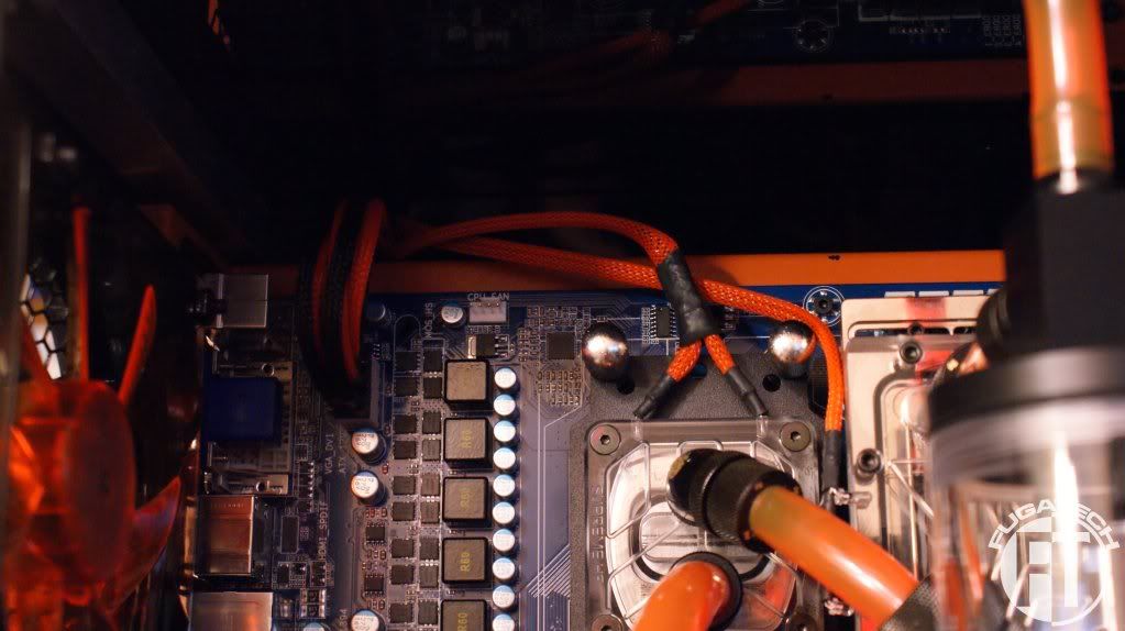
Next I reran the CPU and RAM LEDs behind the mobo. After I flipped them both because I am a noob and mounted the EK sideways on the CPU block and backwards on the RAM block.
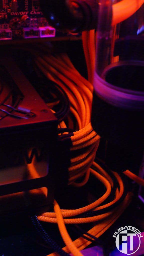
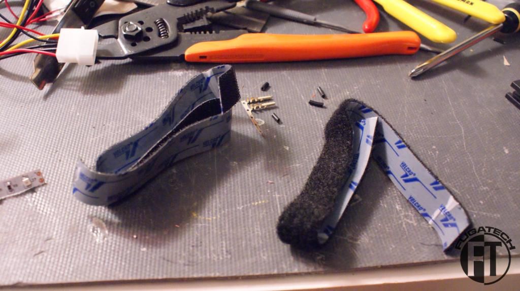
I then installed the 12" Lamptron UV Cold Cathodes in the HDD side of the case using some Velcro.
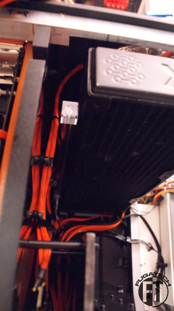
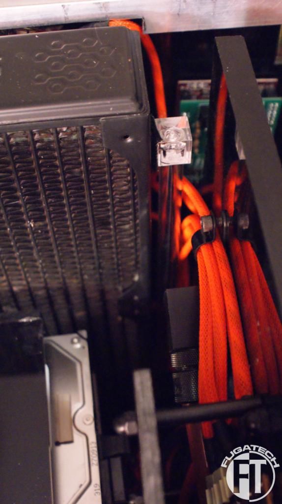
As you can see I mounted them to the Rads because it was the easiest place to put them. They light up the wires and tubing behind the HDDs very nicely.
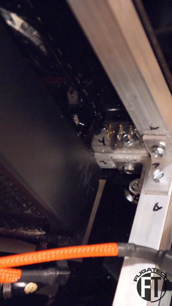
Lastly I installed my Lamptron FC5V2. This will control the 3 fans on the mobo side of the case and the 200mm exhaust fan on the HDD side of the case.
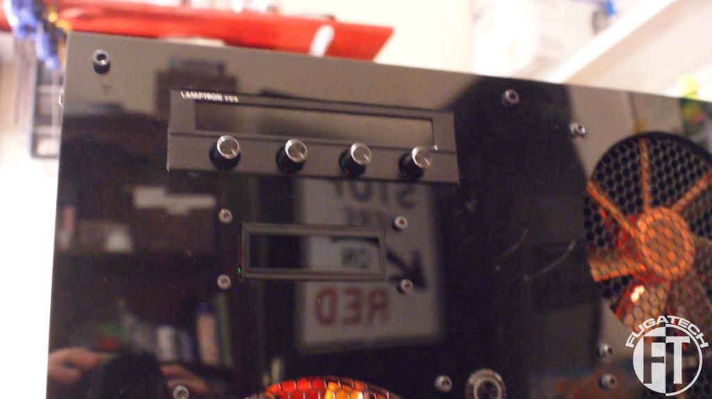
I'll have to clean up the wires later.
Thanks all for today. My MDPC order was lost in the mail so I am waiting to get that so I can finish sleeving the system.
Cheers till next time!
Since I had never used rocker switches before I had to do some testing.
Now how to mount them? I made a sketch so I knew the measurements.
Put on some tape.
Marked
Cut and installed!
It works!
Inside view.
These 3 will control the Mobo door LED, All UV Cold Cathodes on both sides of the case, and the res LEDs.
I put another switch on the HDD side of the case for the HDD door LEDs.
Inside view.
Because I had the CPU block sideways for the AMD chip I had to redo my LEDs.
Next I pulled the top of the case off so it would be easier to work on the next few parts.
I decided I didn't like how the cables looked. They needed to be tied up and hidden better. So I started the process of putting cable ties on.
Looks much much better
Next I reran the CPU and RAM LEDs behind the mobo. After I flipped them both because I am a noob and mounted the EK sideways on the CPU block and backwards on the RAM block.
I then installed the 12" Lamptron UV Cold Cathodes in the HDD side of the case using some Velcro.
As you can see I mounted them to the Rads because it was the easiest place to put them. They light up the wires and tubing behind the HDDs very nicely.
Lastly I installed my Lamptron FC5V2. This will control the 3 fans on the mobo side of the case and the 200mm exhaust fan on the HDD side of the case.
I'll have to clean up the wires later.
Thanks all for today. My MDPC order was lost in the mail so I am waiting to get that so I can finish sleeving the system.
Cheers till next time!
The project is nearing the end. Here is what I'm waiting for to arrive to finish it. Hopefully it should all arrive this week.
- i7 950
- Sleeving
- Heatshrink
- Plexi for midplate
- More Bitspower fittings (mainly T, L and Q fittings)
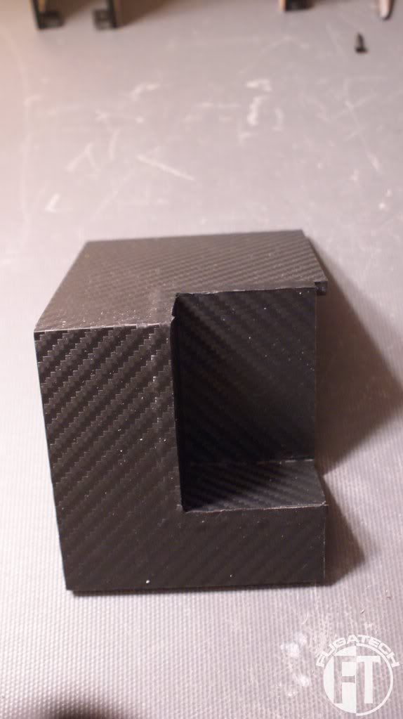
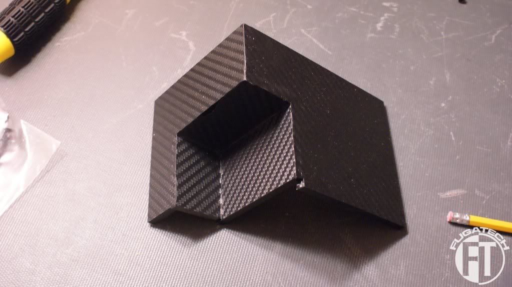
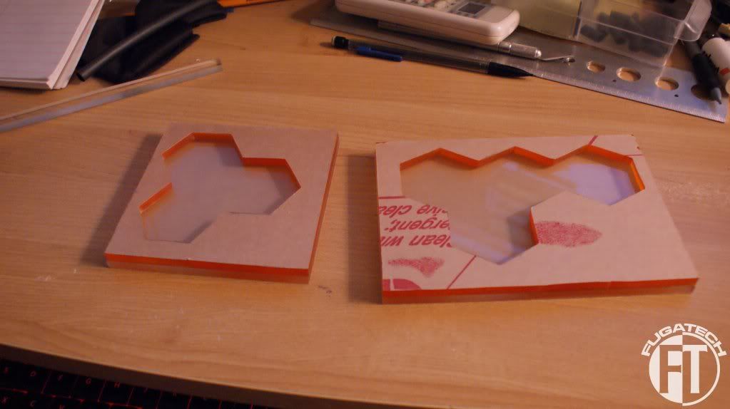
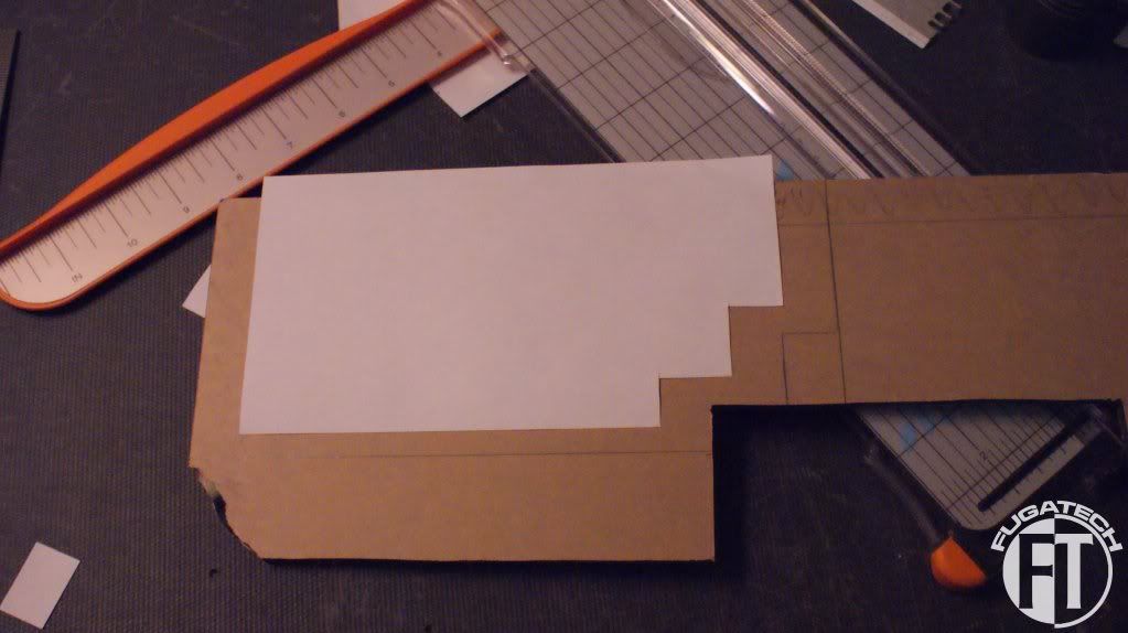
I worked on a new midplate design.
This piece is notched to fit in just perfectly.

I had a scrap piece of 1/4" black plexi glass so I put my template on it and cut.
After I cut it, I bent it.
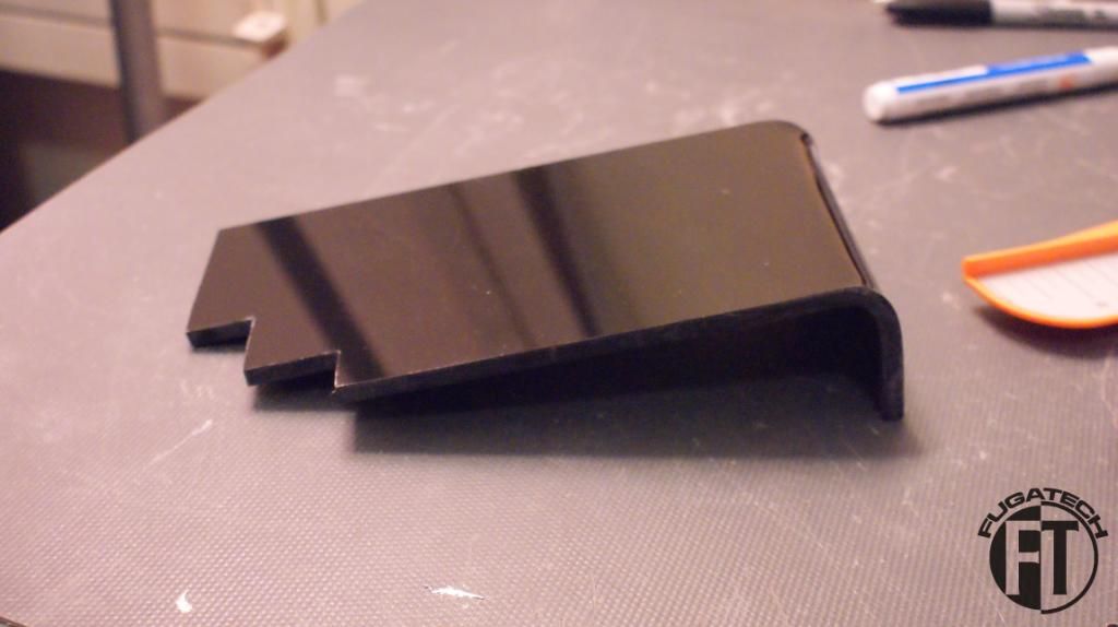
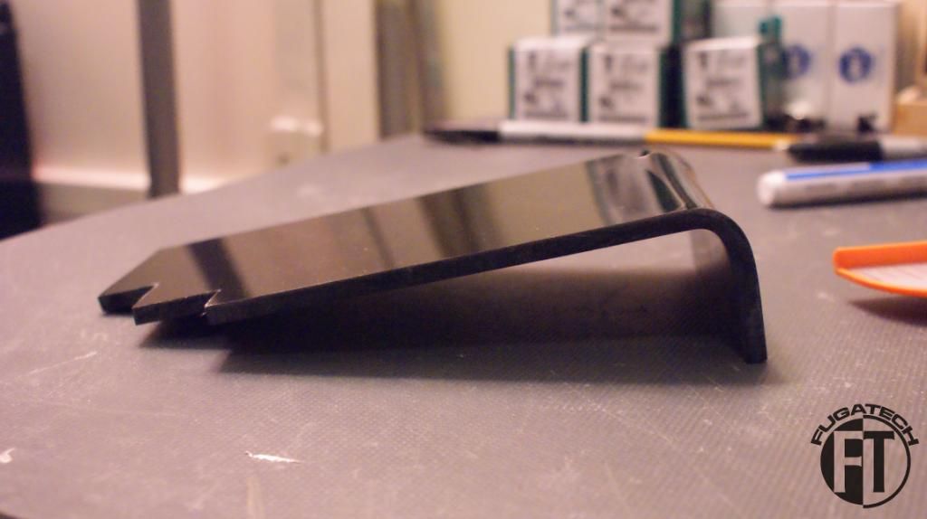
And it was too big

Taped off and marked. I had to cut 1/2" off.

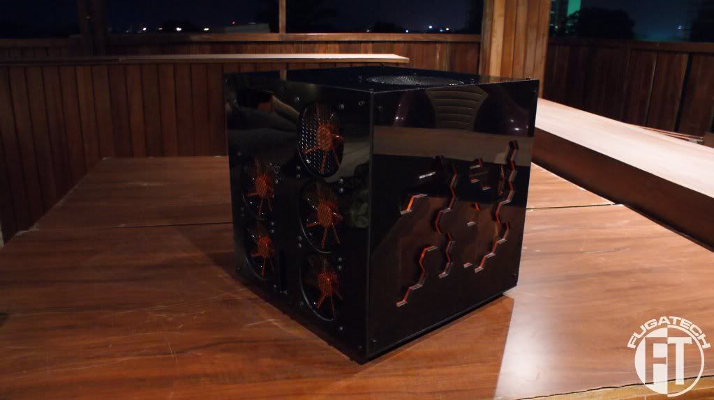
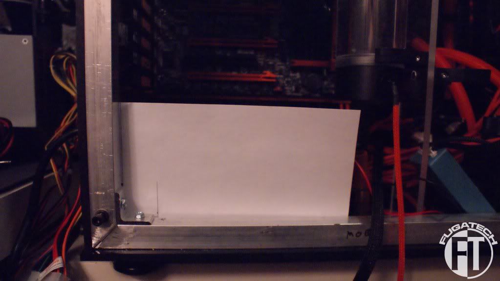
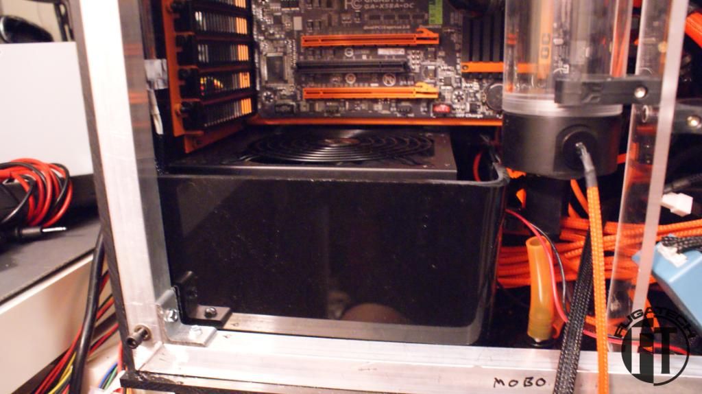
Then it fit just right. You can also see I started the top design already with paper. I ordered 1/8" black plexi for that part.
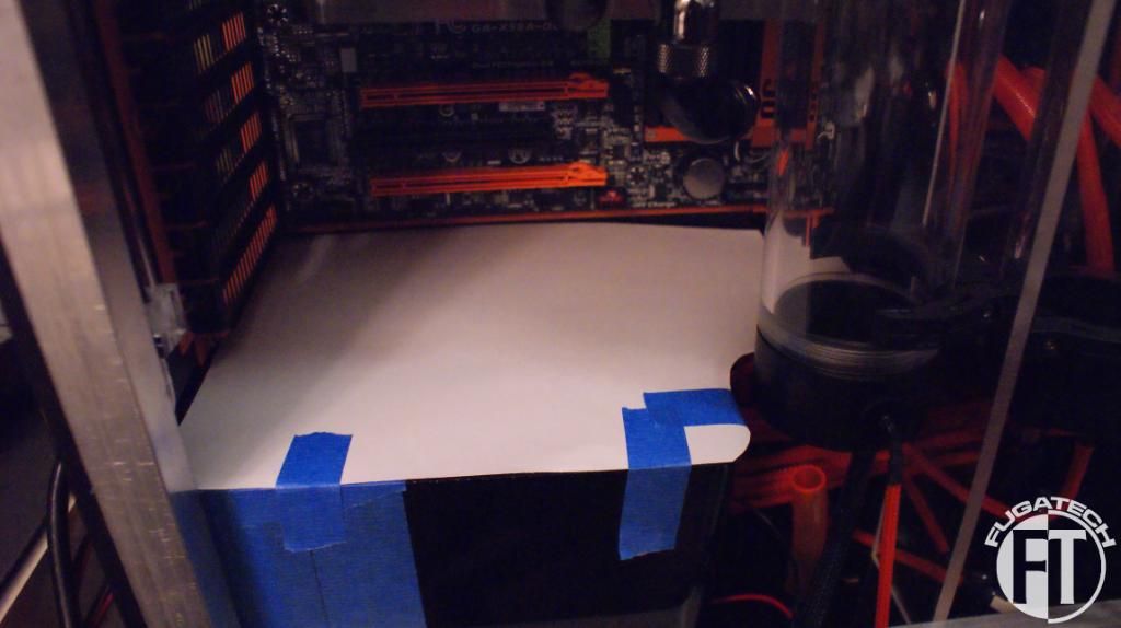

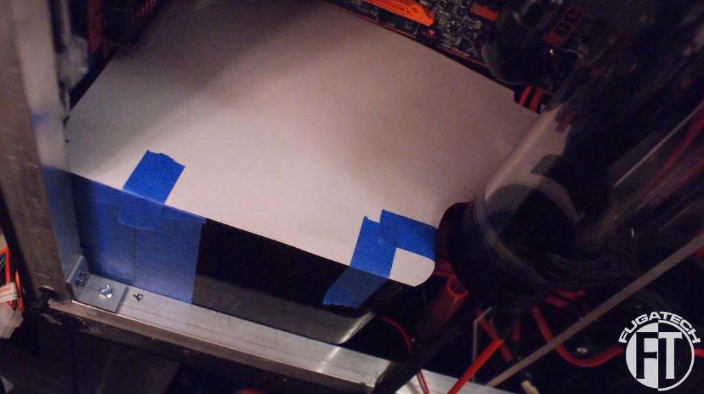
After I get the plexi I will cut it and ship it off to have a honeycomb pattern laser cut into it for the PSU exhaust. Should look pretty boss.
Cheers till next time.
- i7 950
- Sleeving
- Heatshrink
- Plexi for midplate
- More Bitspower fittings (mainly T, L and Q fittings)
I worked on a new midplate design.
This piece is notched to fit in just perfectly.
I had a scrap piece of 1/4" black plexi glass so I put my template on it and cut.
After I cut it, I bent it.
And it was too big
Taped off and marked. I had to cut 1/2" off.
Then it fit just right. You can also see I started the top design already with paper. I ordered 1/8" black plexi for that part.
After I get the plexi I will cut it and ship it off to have a honeycomb pattern laser cut into it for the PSU exhaust. Should look pretty boss.
Cheers till next time.
Awesome build! Where did you get the orange power and reset buttons from?
Thanks man.
I got them from FrozenCPU.com.
linuxfueled
Weaksauce
- Joined
- Mar 12, 2009
- Messages
- 88
nice work, orange black with UV looks great!