24" Widescreen CRT (FW900) From Ebay arrived,Comments.

I will finally get to have my FW900. Its been waiting patiently about 3.5 years for me to get it.

For games there have been advancements in CRU which now can sync games to refresh rate so that with VSync OFF there is no tearing except few lines at the top. It works if framerate is good enough which should not be really an issue even with Ray Tracing really given I could jus use whatever resolution I want with whatever refresh rate I want.

For example here: "Delock 62967,190x1200 96 Hz is guaranteed but if it doesn't work you will need to replace the cable,so if you are able to do it this is the most economical solution".

but Delock is saying 62967 is only 270 Mhz pixel clock, so ... I don't know where the truth is, becouse on paper 1920x1200 96 HZ (331 MHz) is far beyond those specs. That Delock was reported however on forum as: 340-355 MHz. Why those makers cant just tell the true specs ?!.
My Delock works fine at 1920x1200@96Hz (actually 24/1.001 * 4 is the best) on Nv cards. It doesn't have 10bit
I will try making dithering work and report back.
 
congrats XoR :D
Damn, how I missed this big thing :nailbiting:

I ran Quake 2 RTX at 1920x1080@85Hz and it runs 85fps with v-sync constant. I set ray bounce to 2 (maximum), contrast to 1, exposure -2.5, set texture lod to -999 and disabled denoiser completely. I love the looks of this game, truly next gen life like graphics :woot:
FW900 is dream monitor for RTX, especially first gen ones and not costing thousandth bucks. Hell, it is the best gaming monitor ever made, period :woot:

I use Delock 62967 and there are no issues with RTX 2070. With registry tweaks it have dithering so no banding when using gamma correction.
For me this covers 99% of requirements for such digital-analog converter. I might get this USB C adapter if works on RTX cards and is better (supports higher pixel clock and/or true 10bit)
 
Yea, it's a very pretty tube. The main downside to me is that you can't get super high refresh rates at the prime resolution (1920x1200). So if you wanted to game competitively at that res for first person shooters, would be an issue.

Still, it makes up for this shortcoming in many other ways!
 
Damn, how I missed this big thing :nailbiting:

I ran Quake 2 RTX at 1920x1080@85Hz and it runs 85fps with v-sync constant. I set ray bounce to 2 (maximum), contrast to 1, exposure -2.5, set texture lod to -999 and disabled denoiser completely. I love the looks of this game, truly next gen life like graphics :woot:
FW900 is dream monitor for RTX, especially first gen ones and not costing thousandth bucks. Hell, it is the best gaming monitor ever made, period :woot:

Quake 2's single player didnt age all that well but after a couple hours of playing the RTX version and tweaking mouse sensitivity etc. I was hooked all over again, You start noticing a lot of little details that are only possible with ray tracing lol. Like seeing a shadow appear on a wall you're facing only to turn around and realize it's an enemy approaching or how the shiny parts of your weapons fully reflect the world in real-time, explosions light up areas and create shadows just as you'd expect them to in real life etc. it's pretty crazy.
 
Last edited:
Damn, how I missed this big thing :nailbiting:

I ran Quake 2 RTX at 1920x1080@85Hz and it runs 85fps with v-sync constant. I set ray bounce to 2 (maximum), contrast to 1, exposure -2.5, set texture lod to -999 and disabled denoiser completely. I love the looks of this game, truly next gen life like graphics :woot:
FW900 is dream monitor for RTX, especially first gen ones and not costing thousandth bucks. Hell, it is the best gaming monitor ever made, period :woot:

I use Delock 62967 and there are no issues with RTX 2070. With registry tweaks it have dithering so no banding when using gamma correction.
For me this covers 99% of requirements for such digital-analog converter. I might get this USB C adapter if works on RTX cards and is better (supports higher pixel clock and/or true 10bit)

It's nice to see that 62967 works with your new card and good to know that those registry keys for dithering are working, now let's see how long Nvidia takes to implement it officially.
About the USB-C adapter it should works without problems with RTX cards, at boot time and without any need of drivers.
Dithering works but it is extremely finnicky. I basically need to not use sleep mode otherwise dithering is gone. Not sure if enabling/disabling display (in control panel) works or elpt. Hopefully it does.

This USB-C adapter if does support 10bit natively would be better solution. I would still configure dithering for 10bit as normally resolution can be up to 12bit. It wouldn't matter much in this case though.

Quake 2's single player didnt age all that well but after a couple hours of playing the RTX version and tweaking mouse sensitivity etc. I was hooked all over again, You start noticing a lot of little details that are only possible with ray tracing lol. Like seeing a shadow appear on a wall you're facing only to turn around and realize it's an enemy approaching or how the shiny parts of your weapons fully reflect the world in real-time, explosions light up areas and create shadows just as you'd expect them to in real life etc. it's pretty crazy.
I spent a lot of time going through all console commands and settled at setting quite different than default with less automatic contrast control and no denoising at all. With denoising (flt_enable) I would still disable TAA (flt_taa) asd it does way too much filtering. It does remove some residual noise but noise obviously does not bother me :)
Lighting in Quake2 RTX is so far the best I saw in any game. Path tracing lived up to the hype imho :D
 
my fw900 also does some random buzzy sound since about a year, it happens almost every day for short periods of time, and when it happens, i can see an horizontal white translucent line going through the screen from botton to top if i have a white background. fortunately seems no to be causing any issues with the monitor. only notable with a white static background an not too loud, but its very weird.


about that dithering thing some people is talking about recently, just for curiosity, why are you people using it for with the fw900? is it really important? doing a quick search about it, seems to be related to improve banding, however, when checking this banding page test i see no banding and i have not use any dithering setting ever from what i remeber. what is that dithering setting-tweak really useful for?
 
I am having a bad day. After having my upstairs A/C unit fail during the summer in Houston my beloved FW900 will intermittently dim and brighten while being used. It usually takes a bit of time before it starts and seems to correct itself if you tap the side of the case or manipulate the power outlet at the back of the monitor which does fit fairly loose at the cable side . Sadly this only works for a moment as the dimming problem seems to return. I'm pretty clueless when it comes to this kind of stuff but some searching and browsing didn't seem to bring much up. I have dealt with the Windas utillity to some degree in the past but it has been years. Has anyone ever had a similar issue to this? I'd really like to fix this if at all possible.
 
Last edited:
According to what you're saying it looks pretty much like a bad contact.

First of all, try another power cable, that could be an easy to fix issue.
If that doesn't work, unplug the screen, let it discharge for a day, then you should open the case, open the shielding plate hosting the G board (that board is the one directly behind the power outlet). Check the power outlet is properly connected to the G board, check every connector on the G board is properly connected as well. Next step is to check if there aren't bad solders on the G board (you'll have to remove it from it's plate), especially close to the power outlet in your case. Resolder any that may look suspicious (for instance cracked, missing some solder, completely desoldered).

It's unlikely this is an issue Windas could fix so no need to mess up with the settings. ;)
Any cable I have sits fairly loose in the connector sadly, the socket seems pretty worn. Maybe that could be part of the issue? I'll let it discharge today and pull the covers off for a closer look. I've had the thing apart to dust it out over the years but I'm always scared that this thing is going to kill me. Any other advice on what to look for? I'll invite you to funeral if it helps . There might be cake.
 
Any cable I have sits fairly loose in the connector sadly, the socket seems pretty worn. Maybe that could be part of the issue? I'll let it discharge today and pull the covers off for a closer look. I've had the thing apart to dust it out over the years but I'm always scared that this thing is going to kill me. Any other advice on what to look for? I'll invite you to funeral if it helps . There might be cake.
It's funny, I have the same problem with 2 GDM-5410, most cables I have won't sit very well in the connector EXCEPT the cables I received with the screens. But I don't remind using another cable causing the issues you describe though.

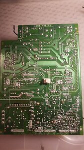
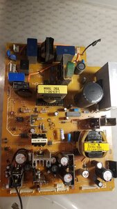
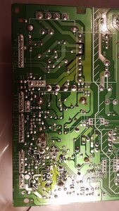
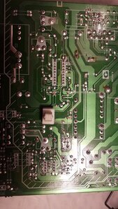
There's not much else I can say, I've never encountered the specific problem you describe and I can only guess. Tapping the screen temporarily solving the problem is a pretty solid clue about bad contact though, the hardest part may be to locate it. If you can take a high resolution picture of the back of the G board and post it here, I may tell you if I spot something wrong with the solders.
Anyway, don't be too scared, it is necessary to be careful especially when you aren't used to electronics and/or that kind of device but there's not much danger manipulating the internals if the screen is unplugged and you waited some time for it to discharge. The worse you risk is a little spark if you ground a circuit with still some voltage inside. Too bad for the cakes. :(
 
I got two new CRTs
kNX5okC.jpg

xMU5S3q.jpg


Pair of awesome SONY PVM 14M2E :cat:
Haven't tested them because they use BNC connectors (on the way, should have them tomorrow) but should be good :)

There is RGB support (for Europe this is not at all unusuall, all SDTV's had RGB inputs for like forever but still imho worth mentioning especially that in US most people get PVM for RGB inputs) and even 16:9 support. Gonna test them with Atari ST, Amiga 600, PS3 and even RPi4 which should be able to not only output 576i (and I guess 480i but who cares :hungover:) but should also allow for custom modes like 47.952Hz >600i for crystal clear almost HD-Ready playback :cool:
 
It's funny, I have the same problem with 2 GDM-5410, most cables I have won't sit very well in the connector EXCEPT the cables I received with the screens. But I don't remind using another cable causing the issues you describe though.

There's not much else I can say, I've never encountered the specific problem you describe and I can only guess. Tapping the screen temporarily solving the problem is a pretty solid clue about bad contact though, the hardest part may be to locate it. If you can take a high resolution picture of the back of the G board and post it here, I may tell you if I spot something wrong with the solders.
Anyway, don't be too scared, it is necessary to be careful especially when you aren't used to electronics and/or that kind of device but there's not much danger manipulating the internals if the screen is unplugged and you waited some time for it to discharge. The worse you risk is a little spark if you ground a circuit with still some voltage inside. Too bad for the cakes. :(

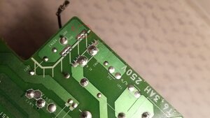
Gotta love image rotation. Let me know if there is any area I should focus on. I circled a wierd spot on the bottom of the board that looked like it was missing a bit of solder.
 

Attachments

  • 20190724_192427.jpg
    20190724_192427.jpg
    518.9 KB · Views: 0
  • 20190724_192559.jpg
    20190724_192559.jpg
    399.1 KB · Views: 0
  • allback.jpg
    allback.jpg
    511.7 KB · Views: 0
  • allfront.jpg
    allfront.jpg
    389.4 KB · Views: 0
  • circle.jpg
    circle.jpg
    237.2 KB · Views: 0
Last edited:
Gotta love image rotation. Let me know if there is any area I should focus on. I circled a wierd spot on the bottom of the board that looked like it was missing a bit of solder.
There's nothing wrong with the spot you indicated. It's an area of bare copper that was covered with solder (not too well), but it's not important as there is no connection here.

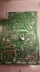
Can you focus on the areas I circled please ? Otherwise I don't see anything that may look suspicious. Electrolytic capacitors look in pretty good external shape BTW, I would have expected at least a few to have a retracted sleeve on the top (usually meaning it's somewhat bulging).

Did you check the noise filter (the power outlet attached to the shielding plate) ? Do any of the 3 pins to sector power seem loose ? Is there anything wrong with the 3 cables leaving the noise filter ? Are they well attached to the filter ? Are the white and red wires well attached to the plastic 2 pins female connector ? Was that connector well plugged on the G board when you removed it ?

Other than that, you mentionned having previously opened the screen to clean it, how far did you go with dismantling when you did so ? Did you touch any of the connectors or cables in the process ?
 

Attachments

  • 228808_allback_1.jpg
    228808_allback_1.jpg
    395.1 KB · Views: 0
Last edited:
Nothing to note with the noise filter other then the overall looseness that I noticed to the case of the monitor. I took some Deoxit and cleaned the connectors to the socketed connections and the contacts on the G-board circled (very carefully). I decided to also add a couple of nuts on the inside to allow a tighter connection between the case and the noise filter in case there was a case grounding issue. So far the monitor has shown no issues after several hours of use with the exact same cable it had a problem with before. I'm sorry if the pictures suck, They were taken prior and I would have to discharge and disassemble the monitor again to get better ones.
 

Attachments

  • 20190724_192413.jpg
    20190724_192413.jpg
    508.6 KB · Views: 0
  • 20190724_192508.jpg
    20190724_192508.jpg
    504.3 KB · Views: 0
Last edited:
So hard to get a decent picture of these things. Still waiting on warmup tonight.
 

Attachments

  • 20190725_193129.jpg
    20190725_193129.jpg
    372.8 KB · Views: 0
  • 20190725_193723.jpg
    20190725_193723.jpg
    247.2 KB · Views: 0
Nothing to note with the noise filter other then the overall looseness that I noticed to the case of the monitor. I took some Deoxit and cleaned the connectors to the socketed connections and the contacts on the G-board circled (very carefully). I decided to also add a couple of nuts on the inside to allow a tighter connection between the case and the noise filter in case there was a case grounding issue. So far the monitor has shown no issues after several hours of use with the exact same cable it had a problem with before. I'm sorry if the pictures suck, They were taken prior and I would have to discharge and disassemble the monitor again to get better ones.
Those 2 pictures don't help much, I really needed a good sharp focus on the spots I indicated. It's hard to say because of the quality of the pictures, but some of the solders may be cracked on the main transformer and/or some voltage regulators. That would explain the problems. In such case, cleaning is useless (these are not contacts, but solders), you absolutely need to grab a solder iron to repair that.
It's also very unlikely you had grounding problems, the case is connected to the earth through the green cable leaving the noise filter, and then there are black cables with clips on all boards connected to the case, sometimes an heatsink performs that connexion too. I don't know what the nuts are but they weren't needed.

Anyway, now you know what to do when/if problems come back, send me good pictures of those spots. ;)
I'll try and pull it again and get some better pictures as soon as I can. thanks.
 
Aparently some versions of the RX 550, a Polaris card, have VGA out.


Of course it's not a good card for modern games. But it makes me wonder if there are test points on the 580 or 5700 where there are VGA signals ready to be tapped.
 
Breaks my heart to say it, but it died this afternoon. All I have on the front face is the blinking orange light instead of green. It will not power on. I tried plugging and unplugging it, but it seems dead. I fiddled with it for a half hour, and moved it to storage. Currently using some crappy 144hz LCD. I did message Uncle Vito, but have not gotten a response, and I don't consider that a good sign. I figure I am pretty much shit out of luck at this point. I don't even know how to get rid of something like that, but I may have to shoot it a lot, and just sweep the pieces into a garbage can for the trash guy to remove it.

My unit seems to be doing the same now.

It started like this:

1st day morning: works for a few minutes then the picture start repeating this: gets blurry over maybe 3 seconds and then it audibly jumps back into focus doing flicking sound as if you would flick your nail over a thin metallic string.

1st day evening: works fine

2nd day morning: same as 1st day morning

2nd day evening: works fine

3rd day morning: same as 1st day morning

3rd day evening: works fine

Its a been about a week now and the behavior is now more erratic where the picture also gets this slight offset jumping on various areas of the screen for a few milliseconds, each with that metallic string sound. This behavior gets worse the longer the monitor is turned on, the symptoms are repeated faster until the whole screen starts doing that (this is where I always turn it off so I am not sure what would happen after this point).

So far it always corrects itself after the unit properly heats up (takes about 5-20 minutes) and then runs fine for hours. I just need to babysit it and power cycle when the symptoms start to show up. Eventually the symptoms fade away. But the next day, its the same shit all over again.

What do you think? Should I start making the necessary arrangements?
 
Well, something is wrong with the electronics and nothing says it can't be repaired but it would probably take someone experienced with electronics troubleshooting and some time to have a chance finding the issue. It may be something as stupid as a bad solder (usually not too hard to see when you know what to look for), or it could be a worn out component somewhat recovering its normal characteristics when heating (much more tricky to find).
 
My unit seems to be doing the same now.

It started like this:

1st day morning: works for a few minutes then the picture start repeating this: gets blurry over maybe 3 seconds and then it audibly jumps back into focus doing flicking sound as if you would flick your nail over a thin metallic string.

1st day evening: works fine

2nd day morning: same as 1st day morning

2nd day evening: works fine

3rd day morning: same as 1st day morning

3rd day evening: works fine

Its a been about a week now and the behavior is now more erratic where the picture also gets this slight offset jumping on various areas of the screen for a few milliseconds, each with that metallic string sound. This behavior gets worse the longer the monitor is turned on, the symptoms are repeated faster until the whole screen starts doing that (this is where I always turn it off so I am not sure what would happen after this point).

So far it always corrects itself after the unit properly heats up (takes about 5-20 minutes) and then runs fine for hours. I just need to babysit it and power cycle when the symptoms start to show up. Eventually the symptoms fade away. But the next day, its the same shit all over again.

What do you think? Should I start making the necessary arrangements?
I had an issue a while back like this but not as bad. It seemed like it was temperature dependent. People commonly refer to the focus popping as a flyback issue (caps sealed inside the flyback leaking), but it could be a power component or short inside the tube. If you have a backup display I would use that and let the FW900 sit it out for a while which may end up resolving the issue after other factors change.

As far as temperature dependence goes, these monitors are definitely sensitive to it. The other person above has their air conditioning fail and suddenly his FW900 has intermittent issues. Moisture levels, large temperature gradients between ambient and operating and high temperatures themselves seem to exacerbate whatever is going on as these units approach MTBF.

The proper fix is always to diagnose and replace parts as necessary, but it helps to just do nothing for a while and not fret too much especially if you don't have the right tools to diagnose and fix things, not to mention parts to swap.

In the meantime check out CRT Collective (FB group) as well as badcaps forum for more general info. But really the workflow from what I've seen is pretty much to test and find bad onboard components (caps or ICs mostly). Stuff like the tube and FBT going are what will put it out of commission in the end.

Edit: bad connections too, though with your issue the popping could very well be a "bad connection" inside the tube itself https://www.repairfaq.org/samnew/tvfaq/tvdoefosv.htm
The "fix" would be to blast possible contamination (metal particulates) with a Sencore CR7000 or even tap on the tube with it face down to knock the stuff out. But with changing temperatures it could simply go away eventually and not be a problem (I suppose the stuff finds its way elsewhere with thermal expansion).
 
Last edited:
SONY PVM 14M2E have so much better colors than GDM-FW900 the latter looks like second grade equipment.
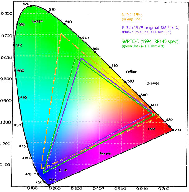
Damn you SMPTE C phosphors. P-22 on this little PVM is better in every single aspect one phosphor can better compared to another.
I cannot fathom why SONY used SMPTE C on FW900 when it is not even sRGB compliant and simply terrible. If they used P-22 there would be no need for any polarizer mods crap and colors would be amazing with no need to do any gamut remapping not to mention FW900 is not even able to reproduce certain colors at all.

Shame on SONY for creating product that was almost perfect but screwed up on most important aspect of it :cry:
 
How is the persistence with the EBU phosphor and PVM electronics? If FW900 didn't have phosphor trailing and had the brighter colors from later generation phosphors it would have indeed been near perfection.
 
Manual/brochure for this monitor differentiate between EBU phosphor for 14M4E and darker P-22 for 14M2E like the one I have.
Many PAL TV sets used phosphor with the same color and colors and I certainly used few of them. Trailing is there but compared to FW900 is less visible, to the point you could live your whole life and not know of any persistence issues :)

By brighter colors do you mean proper Rec.709 gamut?
FW900 is plenty bright as it is... at least until you fix phosphor related contrast ratio nightmare that is:
proxy.php?image=http%3A%2F%2Fi.imgur.com%2F9PqdV6x.jpg

then it is not so bright anymore :p
But to be fair, in 4:3 mode and some zooming out it is pretty bright even with polarizer on. MAybe they did not put better multi-media coating on because they wanted to have higher spec on maximum luminance and larger tube means gun must be much stronger compared to 21" models and it just is not. My guess.

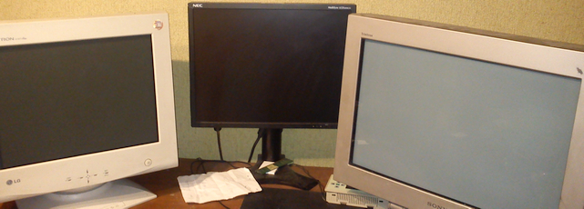
LG in the photo uses what seems to be proper EBU phosphors and some badly made AG sheet and it both had better contrast and colors than FW900 in the state from the photo (no polarizer applied yet). Not so much after I applied polarizer and did EDID hack to get gamut remapping by Radeon card, then except corner cases like very saturated reds and greens FW900 showed superior image. As far as trailing goes polarizer reduced trailing to some extent but it was still inferior to LG or how it is on PVM that I am using now

And when it comes to these PVMs 14M2E: no CRT I ever used produced so awesome colors, EVER. Much brighter and punchier than any CRT and gamma curve seems perfect down to fine dark details to the point black can be set to pure black. It is ridiculously bright and I just used contrast knob and there is also menu options which increase it even more :confused: I drive it at 1920x540i 47.952Hz/50Hz with reduced horizontal frequency to ~14.68KHz (from 15.625Hz for PAL) which was not necessary for getting modes work, I did it because it improve image quality at expense of more audible noise For a SD CRT that actually does 270 lines right there details are surprisingly good :eek:

PVM replaces my HP LP2480zx for watching videos. I do not bother FW900 with such tasks and it is strictly for gaming :)
 
It's funny that they had better (or more) colors in 1953 though I'm not sure about the provenance of this image so it could be wrong.

1492227599284.jpg
 
Thanks Strat_84 and aeliusg, those are some good points. I will see if I can find a local CRT technician to have a look at it with me because this is way beyond my abilities.

So I went to The Stash and swapped it with GDM-F520 so I will be rocking that one for the time being.

Before I hooked it up, I drilled some holes into the plastic cover on the left side so I can later access the FBT pots more easily. Also connected the TTL/USB thingy in the back and snuck the cables through an existing opening a few centimeters above it, this came out perfectly.

So I hooked it up and powered it on. I am greeted by an ugly overbright (black=grey) green picture. I do 3 passes of WPB, each pretty much the same settings and absolutely no issues hitting all the targets.

But... issues.

1------

In the first step of WPB I setup the width and height and position via Windas - yet it was ignored during the subsequent WPB steps and also was not saved/remembered after finalizing (each) procedure.

2------

Under Win8.1, with Sunix adapter, I can see 1600x1200 as the highest resolution in "Control Panel > Display > Screen Resolution" area.

Hooked up via BNC to Win98 I can see 2048x1536 as the highest (which is correct).

I have the F520 Windows drivers installed on Win8.1.

3------

Also any changes made via CRU (Win8.1) are not visible in the "Control Panel > Display > Screen Resolution" area either. Making custom resolutions with Nvidia panel works fine (but its not enough for me because I need the ability to remove resolutions).

4------

Most important issue. After finalizing the procedure, the OSD settings are set to BRIGHTNESS: 50, CONTRAST: 85, MODE: PROFESSIONAL, COLORS: EASY, TEMP: 9300K.

This default setup is different to FW900 (where its 31/90), which doesnt really matter I think, but it does not produce a nice picture, like the FW900 does it after you finalize WPB. The colors are fine (no green anymore etc), but there is something wrong with the gamma/brightness/G2/whatever. On a black pattern I am getting 0.93cdm2 which is a lot, I should be getting 0, and its visibly grey.

I dont think there is any point in doing 4th WPB pass so what I tried now is to do the IMAGE RESTORATION from regular OSD. It did not help with anything or made it worse, no perceived change basically.

I know how the "final" picture should look from my other CRTs and this is obviously not it. The only way I have found out so far, is to change the MODE from PROFESSIONAL to STANDARD, BRIGHTNESS FROM 50 TO 0, and CONTRAST FROM 85 to 100. This way it looks very very similar to what FW900 would look like after WPB but produces only 90cdm2 on fullwhite pattern. This being smaller screen than FW900 I would expect it to reach around 110-120cdm2 (which was one of the 9300K targets by the way, on FW900 that same target was a lower number if I remember correctly).

Apologies for just dumping all this on you but would anyone have any ideas about any of those issues? Thank you!
 
Easiest would be to restore your original DAT file from before the WPBs and try to use image restoration from there. If not you may have to look at manually tweaking the setting of G2 which is what causes all these problems, I think. The greatest fudge factor is that there is no known way to objectively change the setting at the step of adjusting the pedestal level. Adjusting too high and low seems to throw things out of whack. There's also the matter of not knowing how reliable the WinDAS program is being now with all these different Windows setups and TTL-USB chip and driver variations. I did it successfully first on a Vista laptop, but honestly I don't know if it is working properly in Windows 10 at times, despite applying compatibility mode and dropping in the ActiveX file. Part of the problem with trying to maintain these monitors nearly two decades on.
 
Thanks, I have restored to original DAT now so its all green again. Waiting for it to warm up again so I can try the IMAGE RESTORATION, see if that will do anything.

I was also thinking about adjusting one of the FBT knobs. I am not sure if one of those knobs is exactly the same as editing G2 via WinDAS or perhaps it is actually meant to fix the issue I am having. I think the knob is sort of a baseline G2 which is then multiplied by the WinDAS G2 where G2 of 100 would be for example a 1.00x multiplier of the baseline G2. So G2 of 130 would multiply the baseline G2 by 1.3x. That would make sense I guess. But I am only guessing here.

I use WinDAS on Win8 64-bit so I think it should work fine on Win10 too. I think you would be getting error messages if you installed the drivers improperly or they are missing etc.
My advice would be not to disturb the FBT mechanically, but that is only because I am terrified of having these things go out on me. As far as I was aware the FBT is for focus only anyway, but I haven't really looked at it. The conservative thing to do is to rely on image restoration and OSD adjustments only at this point, especially if you are only using it as a backup for now. You wouldn't want two borked CRTs on your hands unless you find a really good guy around you who can work with them. Not to mention the critical parts that now are no longer replaceable.
 
SONY PVM 14M2E have so much better colors than GDM-FW900 the latter looks like second grade equipment.
Damn you SMPTE C phosphors. P-22 on this little PVM is better in every single aspect one phosphor can better compared to another.
I cannot fathom why SONY used SMPTE C on FW900 when it is not even sRGB compliant and simply terrible. If they used P-22 there would be no need for any polarizer mods crap and colors would be amazing with no need to do any gamut remapping not to mention FW900 is not even able to reproduce certain colors at all.

Shame on SONY for creating product that was almost perfect but screwed up on most important aspect of it :cry:

I'm not an expert on phosphors, but what others are saying is that SMPTE C was favored because of greater accuracy/repeatability over P-22 in a professional workflow. If so, this doesn't appear to be a mistake on Sony's part. (Even if some flavors of P-22 were more saturated and pleasing. Though with controlled lighting the FW900 picture is still pretty gorgeous.) Especially, if a variation of the tube used in this GDM is shared with a BVM, which I believe I read somewhere.

Sure, it would have been great if they had conformed to actual sRGB, were unipitch, had a proper baked on coating, etc. And who knows what we would have gotten in a second generation. That we will never know still feels pretty terrible to me.

That said, it's 2019, and this might still be arguably the greatest computer display ever made, which is quite sad. (Until OLED anyway, though that tech might still have some issues...)
 
My advice would be not to disturb the FBT mechanically, but that is only because I am terrified of having these things go out on me. As far as I was aware the FBT is for focus only anyway, but I haven't really looked at it. The conservative thing to do is to rely on image restoration and OSD adjustments only at this point, especially if you are only using it as a backup for now. You wouldn't want two borked CRTs on your hands unless you find a really good guy around you who can work with them. Not to mention the critical parts that now are no longer replaceable.

I looked into the service manuals now and it seems like there is only "FOCUS 1" and "FOCUS 2" knobs on both FW900 and F520. The "SCREEN" knob that I was referring to is present on Mitsubishi 2070SB for example, that one has 3 knobs in total.
 
F520 has warmed up now and I ran the IMAGE RESTORATION. I then had to lower BRIGHTNESS from 50 to 42 to achieve black level. On fullwhite pattern I am now getting:

x = 0.3188
y = 0.3348
Y = 80.180

The white balance is not perfect but its obviously much better than a green picture. The 80cdm2 is again a let down though. I will save this into DAT and load the previous 3rd WPB DAT, see if that will make any difference. If there wont be a difference I will do 1 WPB pass. If there will be a difference after either of those steps then that would be an important discovery I think.
 
Loaded that 3rd WPB DAT now, fullwhite pattern results:

x = 0.283
y = 0.298
Y = 65.8

Well, color is great but 65cdm2 is very bad... (it was 90 before, haha). Will do that WPB now, perhaps it will allow me to go for a different G2 value than in those previous 3 WPBs.

edit: I made a mistake I forgot to switch from PROFESSIONAL to STANDARD image mode (as I did before). After that it is 81.2cdm2, which is still worse than before but not as much.
edit2: I may have forgot to adjust CONTRAST from 85 to 100 as well so it would probably be around the same as before so it seems like IMAGE RESTORATION did not have any effect here. So perhaps the only bad thing about IMAGE RESTORATION is that you cannot undo it without a new WPB procedure.
 
Last edited:
Okay, so I am getting 88.3cdm2 on fullwhite pattern after doing this (lets recap):

WPB 1 > WPB 2 > WPB 3 > ORIGINAL DAT RESTORED > IMAGE RESTORATION > WPB 4

So no change when I compare it to point "WPB 3" from the above chain of events.

And 88.3cdm2 is only after messing with those OSD settings (change the MODE from PROFESSIONAL to STANDARD, BRIGHTNESS FROM 50 TO 0, and CONTRAST FROM 85 to 100).

Something is obviously wrong here, cant put my finger on it. Was thinking I forgot a loaded profile but I dont have any apps that do that running and doing dispwin -c as admin does exactly nothing so this is not it.

edit: running IMAGE RESTORATION after the last event in the above chain of events results in pretty much no difference.

I am pulling my hair out here. I think even the OSD is laughing at me now because the white color in OSD is 200cdm2. How does it even...ffs
Experienced this during my last WPB in Windows 10 on FW900. My Vista setup is no longer available so I couldn't do a quick test to see if that made a difference. What are you using for your color calibrator? I was unsure if my DTP94 was still accurate but it turned out to be okay.

Basically I think the G2 is messed up. The white spot in OSD can hit over 200 nits because the whole screen doesn't go over the ABL, definitely symptomatic of the underlying issue however. I would try modifying the G2 via the hacky way (in the advanced settings or whatever that people used before the WPB to change the value manually)

G2 as it relates to C_MAX_B_MAX and the other drive voltages. Tread carefully, the ABL should protect the monitor, but something is definitely not right if you're getting 200 nits and the tube is at risk for sure.
 
Last edited:
Back
Top