X51 PSU arrived

Machupo

Gravity Tester
Joined
Nov 14, 2004
Messages
5,756
330WDCPSU_zpse099f093.jpg


Picked up one of these for the next evolution of Neutronium (yes, we're going smaller with more power :p)

Has anyone played with them in high-output environments? I'm pulling right around 300W with concurrent prime95 and furmark, but want to go a bit bigger on the video card front (cpu front as well). Any RW experience, issues, concerns, comments?

I've already got a better (and quieter) fan to bolt on there, but other than that I haven't seen much about these boards.
 
Did you get the external power block with it and the cable that mounts outside the case for the adapter to plug into? It goes to the DC_19V plug if I'm not completely mistaken.
 
Did you get the external power block with it and the cable that mounts outside the case for the adapter to plug into? It goes to the DC_19V plug if I'm not completely mistaken.

jeez, you would think right?

I see no transformer or rectifier, 19VDC in and this is just regulators and protection makes sense...sorry OP, no experience with these, interesting though
 
Did you get the external power block with it and the cable that mounts outside the case for the adapter to plug into? It goes to the DC_19V plug if I'm not completely mistaken.

Yeah -- I've got that cable (and the 330w brick), it plugs into the black 6-pin connector (JPWR). The only thing I'm trying to run down is why the P4 connector is labeled 19VDC... i sure hope that Dell doesn't use proprietary 19V CPU power on their motherboards (or I'll have to find a way to crank it down to 12VDC).

[edit]This page has me believe that it's actually the 12VDC standard, but why the odd silkscreen on the power pcb then? It's a mystery...[/edit]
 
Last edited:
It might not be the P4 output. The brick outputs 19v, and that may just be a pass through to allow access to that voltage line.

Id get a voltmeter and test it before plugging something into it.
 
It might not be the P4 output. The brick outputs 19v, and that may just be a pass through to allow access to that voltage line.

Id get a voltmeter and test it before plugging something into it.

Oh yeah -- definitely will test it -- I just hope it powers up without anything plugged in :)

In pictures on the web, though, that "DC 19V" 4-pin plug is directly connected to the P4 connector on the motherboard... it just seems weird that Dell would go to that length to have a custom-voltage power circuit for the CPU (that they would then have to downvolt to 12V anyway); why not do it directly on the power board and use industry standard power circuitry on the motherboard... of course, it could just be FUD, i'll plug a multi into it and see what I get.
 
Smallest i can see a case getting and still fit a dual slot graphics card is around 4.5 liters. 13" wide, 7" deep and around 3" thick. Would require an external brick PSU, and the graphics card would need to be on a riser.

Only problem is this case doesn't exist. Is this what your thinking of doing, and if so are you getting the case custom made or hacking a similar sized case down?
 
Yeah, I'm at 6.9L right now... Going smaller is going to be incremental at this point as I'm not sure I want to switch to the riser form factor just yet. If anything, it's a good excuse to get a better 3D printer :p
 
Smallest i can see a case getting and still fit a dual slot graphics card is around 4.5 liters. 13" wide, 7" deep and around 3" thick. Would require an external brick PSU, and the graphics card would need to be on a riser.

Only problem is this case doesn't exist. Is this what your thinking of doing, and if so are you getting the case custom made or hacking a similar sized case down?

Yeah, doing some quick measurements, I think I could get to 360mm by 50mm by 180mm which gives 3.24L if I used a riser on my stubby GTX670 and the x51 psu. That would have to be a scratch build, unfortunately. It would be super tight and might have to change a bit if the risers aren't actually shaped like I think they are in my head :p

Ventilation would be eeeentaresting...

Though I just noticed that with this proposed form factor, you can jimmy it to a nice 1:4:9 ratio (say 45mm thick by 180mm wide by 405mm tall), you could bury the bottom 40mm or so of the height in a fake rock pile and have small gorillas with femurs in their hands dancing around it and shouting... oh yeah, and it'd have to be matte black :D
 
Last edited:
Though I just noticed that with this proposed form factor, you can jimmy it to a nice 1:4:9 ratio (say 45mm thick by 180mm wide by 405mm tall), you could bury the bottom 40mm or so of the height in a fake rock pile and have small gorillas with femurs in their hands dancing around it and shouting... oh yeah, and it'd have to be matte black :D

You are awesome! :D
 
45mm is 1U thick, you'd have to use 1U heatsink/fan on the CPU.

Case volume would be 3.28 liters.

In inches it would be 1.75" x 7" x 15.75" which is slightly smaller than if you went by the 1:4:9 starting with 45mm.
 
Last edited:
This 350w Flex ATX PSU could probably fit in a case measuring 45x180x405mm

http://www.newegg.com/Product/Product.aspx?Item=N82E16817338063

You wouldn't even need an external power brick.

Though if you made it not so wide/tall, used a power brick, you could get it even smaller.

Look at this case: http://www.b2b-computer-case.com/rimages/386/mini-itx-case-03-04-B.jpg
2 expansion slots and its only 300mm wide.

So if you went down to that, it'd be 2.43 liters.

For reference: (W / H / D) laying flat
Xbox One: 340 x 85 x 250mm
Xbox 360: 309 x 83 x 258mm
Xbox 360 slim: 270 x 75 x 264mm
PS4: 275 x 53 x 305mm
PS3: 325 x 98 x 274mm
PS3 slim: 290 x 65 x 290mm
PS2: 301 x 78 x 178mm

So at 300 x 45 x 180mm it would be about the same size as the original PS2, only thinner.
 
Last edited:
Took a bit of googling, but apparently 1u heatsinks are limited to 29mm in height.

You could get a shorter 1u style copper block heatsink and fit a large slim 120mm fan over it like the one from scythe.

http://www.newegg.com/Product/Product.aspx?Item=N82E16835230006
http://www.amazon.com/Scythe-Kaze-Jyuni-Slim-Stream-120mm/dp/B002CYPWTG

You might need some low profile ram sticks for the fan to fit over the motherboard like these:
http://www.newegg.com/Product/Product.aspx?Item=N82E16820148663

You'd probably want to get a 35w TDP haswell for this since cooling wont be very good. Like this:
http://www.acmemicro.com/Product/12...466203-LGA1150-Quad-Core-2-9-GHz-4MB-35W-Tray

It's dual core, hyper threading, and turbo's up to 3.6Ghz.

I've had this idea in my head for a while now for an itx case with graphics on a riser, except its a flexible riser and the card is inverted so it faces up like the motherboard. Then flip the case so they are facing down with some rubber feet, and have the fans on the CPU heatsink and graphics card pull in air from underneath the case and exhaust out the back and sides. One of the benefits of the flexible riser is you don't have to make the case wider to make room for PCI-e power cables on the side of the graphics card, and then also you wouldn't need the extra width needed to slot the graphics card in. Since the riser is flexible it would reach up outside the case to connect your card to it, and you could drop it straight down in. Would make installing graphics cards in a case this small much easier.

Riser card:
http://www.ameri-rack.com/ARC1-PERX16A1-Cx_m.html

Would have to custom order a longer length. Might take a few orders to get just the right length. I'm guessing around 150mm.

I should have my PC back up and running next week, then I'll throw this into Sketchup and see how small i can get this.
 
Last edited:
As an Amazon Associate, HardForum may earn from qualifying purchases.
Sorry for all the posts, really interested in this new idea.

I just remembered, i was really interested in this external brick. Could you measure it for me please? I couldn't find the size of the external brick anywhere.

Can you measure the DC power board also?
 
Last edited:
Sorry for all the posts, really interested in this new idea.

I just remembered, i was really interested in this external brick. Could you measure it for me please? I couldn't find the size of the external brick anywhere.

Can you measure the DC power board also?

Here's a thread with a decent concept of how massive this brick is (check out the picture): http://hardforum.com/showthread.php?t=1738116

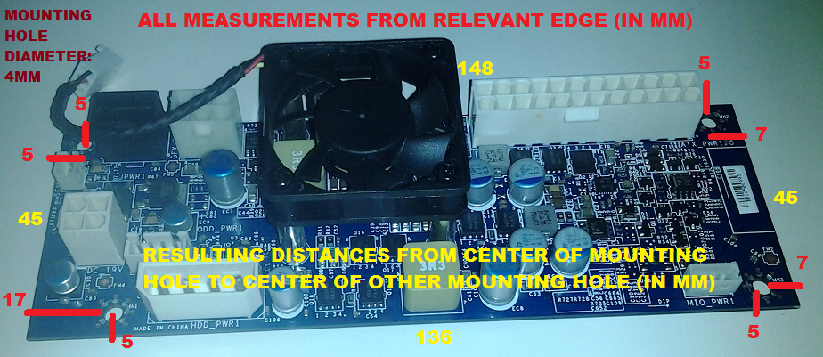
The powerboard is 55mm by 160mm and is 29mm tall without standoffs (so call it 35mm thick for mockup purposes).

where and how did you get that PSU?

eBay.

Took a bit of googling, but apparently 1u heatsinks are limited to 29mm in height.

You could get a shorter 1u style copper block heatsink and fit a large slim 120mm fan over it like the one from scythe.

http://www.newegg.com/Product/Product.aspx?Item=N82E16835230006
http://www.amazon.com/Scythe-Kaze-Jyuni-Slim-Stream-120mm/dp/B002CYPWTG

You might need some low profile ram sticks for the fan to fit over the motherboard like these:
http://www.newegg.com/Product/Product.aspx?Item=N82E16820148663

You'd probably want to get a 35w TDP haswell for this since cooling wont be very good. Like this:
http://www.acmemicro.com/Product/12...466203-LGA1150-Quad-Core-2-9-GHz-4MB-35W-Tray

It's dual core, hyper threading, and turbo's up to 3.6Ghz.

I've had this idea in my head for a while now for an itx case with graphics on a riser, except its a flexible riser and the card is inverted so it faces up like the motherboard. Then flip the case so they are facing down with some rubber feet, and have the fans on the CPU heatsink and graphics card pull in air from underneath the case and exhaust out the back and sides. One of the benefits of the flexible riser is you don't have to make the case wider to make room for PCI-e power cables on the side of the graphics card, and then also you wouldn't need the extra width needed to slot the graphics card in. Since the riser is flexible it would reach up outside the case to connect your card to it, and you could drop it straight down in. Would make installing graphics cards in a case this small much easier.

Riser card:
http://www.ameri-rack.com/ARC1-PERX16A1-Cx_m.html

Would have to custom order a longer length. Might take a few orders to get just the right length. I'm guessing around 150mm.

I should have my PC back up and running next week, then I'll throw this into Sketchup and see how small i can get this.

As to the "flexible" risers... they're really not that flexible (if you get the shielded variety, which is the only way you're going to get good signal transmission), I have a 200mm one that struggles to allow the card to be flipped and then bows out so much that it wouldn't work well with this small of a case. Might have to figure out a custom riser.
 
As an Amazon Associate, HardForum may earn from qualifying purchases.
where and how did you get that PSU?

330w brick - $29 - http://www.amazon.com/gp/product/B009IPUBTS?tag=at055-20
DC/DC board - $120 - http://www.impactcomputers.com/d0hy5.html
Cable to connect them - $50 - http://www.impactcomputers.com/2yg07.html


Here's a thread with a decent concept of how massive this brick is (check out the picture): http://hardforum.com/showthread.php?t=1738116

The powerboard is 55mm by 160mm and is 29mm tall without standoffs (so call it 35mm thick for mockup purposes).

As to the "flexible" risers... they're really not that flexible (if you get the shielded variety, which is the only way you're going to get good signal transmission), I have a 200mm one that struggles to allow the card to be flipped and then bows out so much that it wouldn't work well with this small of a case. Might have to figure out a custom riser.

That thread didnt measure the brick. Could you please?

I've had flexible risers, they can be manipulated if you work on them. Their stiff but not unworkable. You just have to get them long enough to orient the card the way you want.

That link i put lets you custom order any length so you can get it just right so theirs no excess bowing out in the wrong place.
 
Last edited:
As an Amazon Associate, HardForum may earn from qualifying purchases.
So I've been thinking about how small, realistically we could get this. The problem i see is the DC/DC power board. I think the best place for it would be the top inside panel at the front of the case, opposite the motherboard. It could probably overlap the board a little, but would have to be deep enough so as to clear the ram slots.

Another possible consideration is making it thick enough for 25mm thick fans over the motherboard. Necere says 11mm from the outside of the case to the top of 8mm standoffs is pretty much as short as you can get while still having a separate motherboard tray so the standoffs dont stick through the outer panel of the case. Motherboard is around 2mm thick. Standard RAM is 30mm tall. Now we could design it around low profile RAM, like the ones above are 20mm which is slightly lower than the RAM slot retention clips. So maybe allow for 25mm at the shortest? Then 25mm for a fan.

So... 11+2+25+25=63mm. Then another 1-2mm for wiggle room + thickness of the metal on the top of the case. 65mm seems like the lowest you could go with the above considerations.

Another thing to think about is a CPU cooler. Other than short 1U block, the lowest (decent) cooler i can see is the NH-L9i which is 23mm for just the heatsink. Necere says from side of case to top of CPU is around 19-20mm, then 25mm for a fan would be around 68mm.

Now you could design it around a slim fan, but there arnt a ton of slim 120mm fans to choose from. That would give you around 10mm shorter, so 55mm thick.

I think 300mm is as thin width wise as you could go, even that might be difficult depending on the type of riser used, and the method of plugging in graphics cards. Depth on the other hand is something we can wiggle a bit depending on how we position that power board inside the case.

If your goal is "under 4 liters" then you could do 300 x 65 x 205mm (W/H/D) and be inside that. That would give you 35mm in front of the motherboard to put the power board either on the inside of the front panel, or inside the top panel at the front.

The more i think about it, our best bet might be to go with this http://www.e-itx.com/ga620.html and just modify the depth since the hight and width are pretty much perfect. It's 300 x 65 x 273mm (W/H/D). You might have to get rid of the exterior panels and fabricate new ones to bolt to the frame, but even that would be way easier than trying to get something custom made from scratch.
 
Last edited:
Found this today:
http://www.rackmountnet.com/rackmount-chassis-bays-extra-short-depth-200w-power-supply-p-2948.html

Its under 4 liters. They say its a 1u PSU, but i think its technically "flex atx". I think the only difference between the two is depth, with 1U's being longer depth than flex.

You could put that 350w flex PSU i linked earlier and have a gaming rig nearly mod free under 4 liters. The rear expansion slot is only cut for 1 slot, so you'd need to cut an opening for a two slot card.

Here's a 400w flex atx PSU that would fit: http://www.newegg.com/Product/Product.aspx?Item=N82E16817338080
 
Last edited:
Picked up one of these for the next evolution of Neutronium (yes, we're going smaller with more power :p)

Has anyone played with them in high-output environments? I'm pulling right around 300W with concurrent prime95 and furmark, but want to go a bit bigger on the video card front (cpu front as well). Any RW experience, issues, concerns, comments?

I've already got a better (and quieter) fan to bolt on there, but other than that I haven't seen much about these boards.

Do you even need a fan? I am gussing the design constraints of the x51 require direct cooling.

My Antec ISK case has great airflow going right over my PSU so I have excellent PSU temps.

I know a big downfall of some of these smaller PSUs is that they have no 12V filter. The X51 version is definitely a lot more modern than mine. I really want to test the two.

Why not send your unit to johnnyguru for a full review?

My setup:
http://hardforum.com/showpost.php?p=1036283223&postcount=173
 
I'm planning on using this PSU in a tiny case as well, I want to be able to support an overclocked i7 with a decent GPU. It seems fairly straight forward, however I'm going to create custom cables instead of using the Dell supplied ones, you can get the 4pin din plug for the brick seprately and just solder your own wires to it. With the 330W brick you should be able to support some decent hardware. Interested in how it turns out for you as I haven't bought my components yet besides the case, I want to do measurements before I get anything.
 
Sorry for all the posts, really interested in this new idea.

I just remembered, i was really interested in this external brick. Could you measure it for me please? I couldn't find the size of the external brick anywhere.

Can you measure the DC power board also?

Sorry bro, didn't see your question here.

The brick is 198mm x 98mm x 43mm.
 
@Machupo, Would it be possible to get approx mounting hole dimensions?

Thinking about making a bracket for my Lone Industries case for a couple people. It replaces the hard drive bracket, so those using it would have to get inventive, or use onboard mSATA for storage:

9576916921_e810b4f312_c.jpg


Or something like this:
9579907252_cd3bbef679_c.jpg
 
Last edited:
@Machupo, Would it be possible to get approx mounting hole dimensions?

Thinking about making a bracket for my Lone Industries case for a couple people. It replaces the hard drive bracket, so those using it would have to get inventive, or use onboard mSATA for storage:

How did you know I wanted one of those? :confused: :D
 
How did you know I wanted one of those? :confused: :D

I'm sure you could probably make one pretty easily. I just figured I'd see how much it'd cost to make a few, in case it saves anyone a little time. :) I still don't know how much it'll cost yet, so it might not be an option after all.
 
little update: everything on the PSU board lines up voltage-wise except for the 4-pin additional mobo power supply. Standard ATX is 12VDC (ish), the x51 board pumps it out at 19.5VDC... don't think the mobo is going to take kindly to that ;)

Might have to build a small step-down circuit.

Anyone tried one of these?


edit: have a couple on the way -- will test them out soon and report back :)
 
Last edited:
As an Amazon Associate, HardForum may earn from qualifying purchases.
In pictures on the web, though, that "DC 19V" 4-pin plug is directly connected to the P4 connector on the motherboard... it just seems weird that Dell would go to that length to have a custom-voltage power circuit for the CPU (that they would then have to downvolt to 12V anyway);
CPUs don't use 12V, they use a mixture very low voltages. There isn't going to be much difference between a 12V to 1.xV converter and a 19V to 1.xV converter.

why not do it directly on the power board and use industry standard power circuitry on the motherboard.
Reducing the number of conversions improves efficiency and reduces cost. Sure some slight design alterations will be needed to the power circuitry on the motherboard so it can work safely at an input voltage of 19V but they will be fairly minor (probablly just uprating a few components) and no problem for a company like dell.

Of course it is a big problem for hobbyists trying to reuse the parts as we don't have the buying power ask a motherboard manufacturer to supply a 19V version of thier board or even to tell us what parts need uprating.
 
CPUs don't use 12V, they use a mixture very low voltages. There isn't going to be much difference between a 12V to 1.xV converter and a 19V to 1.xV converter.

I know that they use tiny voltages :p I'm just curious why that aux 12v plug is sometimes called "cpu power" in popular lingo.

So you're saying that the board can already accommodate 19v? Do you have any references/datasheets for this?


Of course it is a big problem for hobbyists trying to reuse the parts as we don't have the buying power ask a motherboard manufacturer to supply a 19V version of thier board or even to tell us what parts need uprating.

I'm half tempted to just plug it up and see what happens :eek:
 
I know that they use tiny voltages :p I'm just curious why that aux 12v plug is sometimes called "cpu power" in popular lingo.

So you're saying that the board can already accommodate 19v? Do you have any references/datasheets for this?
I'm half tempted to just plug it up and see what happens :eek:

I do not think that plug supplies 19V, its possible the silkscreen is not in reference to the CPU plug at all but the one next to it. People have successfully used the andromeda PSU with other boards than the stock Dell.
 
I do not think that plug supplies 19V, its possible the silkscreen is not in reference to the CPU plug at all but the one next to it. People have successfully used the andromeda PSU with other boards than the stock Dell.

No, I checked it with a multimeter, it definitely provides 19.50VDC :cool:
 
No, I checked it with a multimeter, it definitely provides 19.50VDC :cool:

Whoops, missed that somehow. Probably shouldn't post when I've been up for 40 hours. I guess it must not matter then because I've seen a them used with other boards without any problems.
 
I know that they use tiny voltages :p I'm just curious why that aux 12v plug is sometimes called "cpu power" in popular lingo.
Because it's used to feed the DC-DC converters that generate CPU voltage.

So you're saying that the board can already accommodate 19v? Do you have any references/datasheets for this?
No what i'm saying is that the changes to the circuitry on the motherboard required to support 19v on the CPU power connector are likely to be fairly minor.

For a company like Dell asking the motherboard vendor to swap a few parts in the power circuit so it can support 19v is going to result in a cheaper product than adding an extra stage of conversion.

Unfortunately as I said we don't have the buying power that dell does. So we can't get the schematics for the power circuits on the motherboard and therefore we can't work out exactly which parts need to be changed.
 
Mach, have you checked the voltage at the molex connector?
 
Mach, have you checked the voltage at the molex connector?

No, but it's set up for hard drives, so it should only provide 12vdc and 5vdc per the specification. Now that you mention that, probably nowhere near the connector max of 11A because I don't see any heatsinks. At any rate, I broke down and bought a hall-effect multimeter, so I'll check the 12V cables in both the aux connector and 24-pin connector under several use cases and graph something up.

No what i'm saying is that the changes to the circuitry on the motherboard required to support 19v on the CPU power connector are likely to be fairly minor.

For a company like Dell asking the motherboard vendor to swap a few parts in the power circuit so it can support 19v is going to result in a cheaper product than adding an extra stage of conversion.

Unfortunately as I said we don't have the buying power that dell does. So we can't get the schematics for the power circuits on the motherboard and therefore we can't work out exactly which parts need to be changed.

Yeah, definitely a drag on the DIY community, but then, that's also part of the fun.
 
AUX load topped out @ 4.90A w/ furmark + 8T of p95 blend, full graph in the thread over in the PSU subforum.

TLDR; CPU power is provided through the AUX, peripheral (including PCIe) power is provided through the 24-pin.
 
AUX load topped out @ 4.90A w/ furmark + 8T of p95 blend, full graph in the thread over in the PSU subforum.

TLDR; CPU power is provided through the AUX, peripheral (including PCIe) power is provided through the 24-pin.

I did a ton of researching and found at least 3 people using that PSU for separate builds and one guy that got an EVGA stinger into the X51 case with some dremel work. I'm wondering how it would work with a Q-series board that is made to accept 19V from a brick already.
 
Back
Top