Navigation
Install the app
How to install the app on iOS
Follow along with the video below to see how to install our site as a web app on your home screen.
Note: This feature may not be available in some browsers.
More options
You are using an out of date browser. It may not display this or other websites correctly.
You should upgrade or use an alternative browser.
You should upgrade or use an alternative browser.
Project: TYPHOON (Stacker+ GTX480) **2010 REBUILD**
- Thread starter JonCl
- Start date
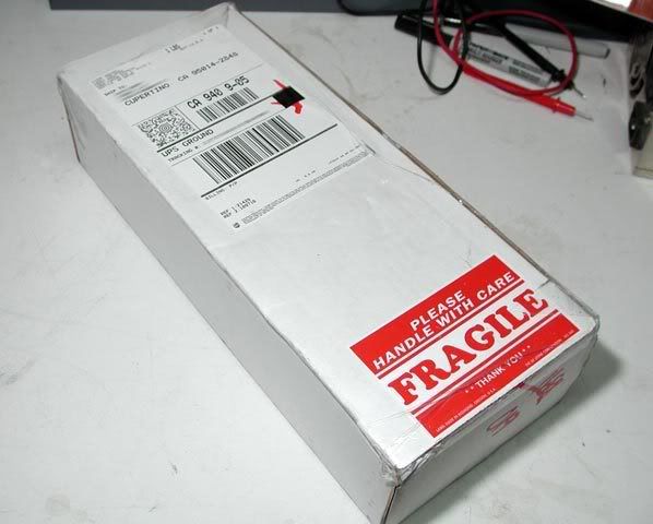
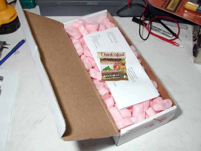
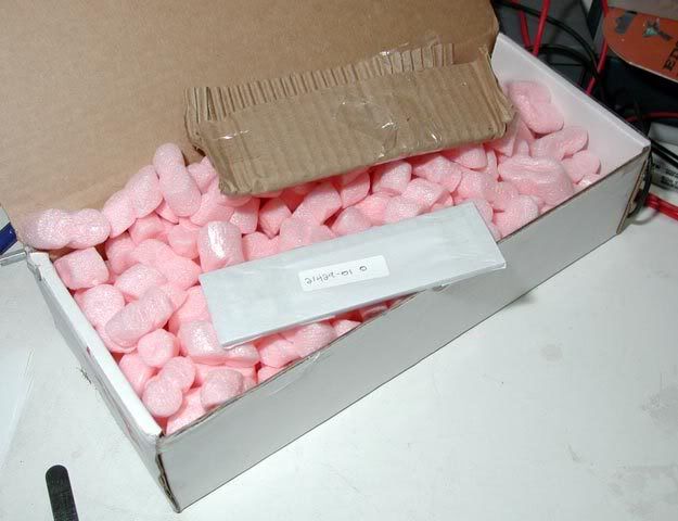
Here's a quick update. I probably won't have much of a chance to do anything this week, but I had to at least post some pics of what arrived in my mail box today... 
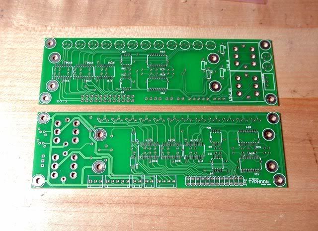
The front panel PCB was ordered on 5/7, shipped on 5/18, and arrived today (5/19). Not bad! And the quality is excellent! They even printed two of them when only one was ordered. Very nice of them! I think I need the second one for soldering practice anyway.
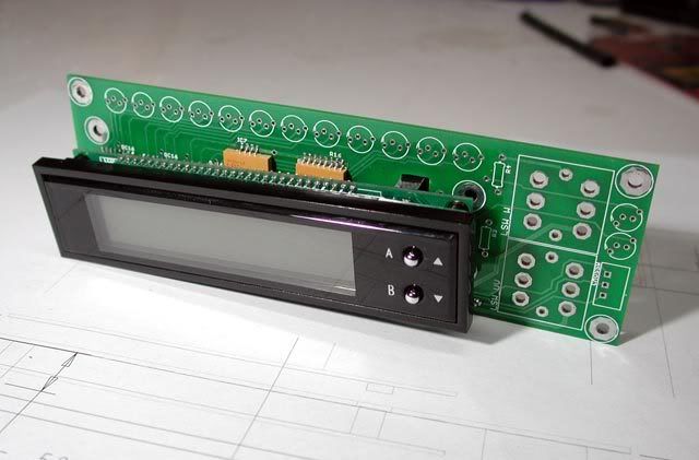
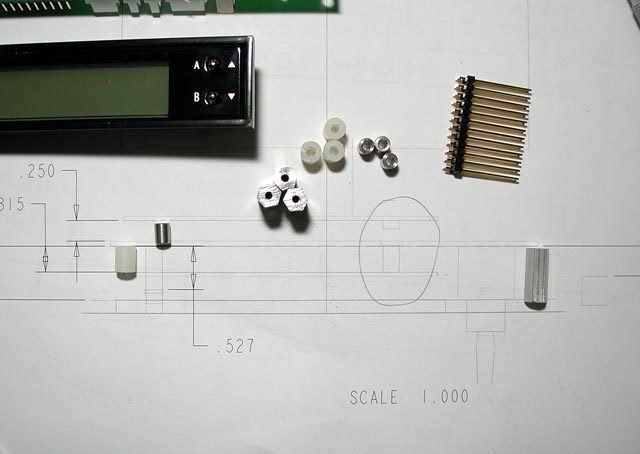
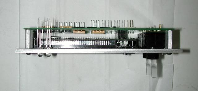
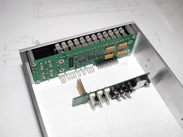
I've collected most of the components, and now it's just a matter of soldering them on. Here's a few of them in place. So far, they all fit perfectly!...
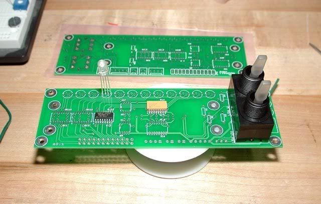

The next update will be about my soldering experience, and then powering it up for the first time. Can't wait for that! (man, do I hope it works)
-- stay tuned...
The front panel PCB was ordered on 5/7, shipped on 5/18, and arrived today (5/19). Not bad! And the quality is excellent! They even printed two of them when only one was ordered. Very nice of them! I think I need the second one for soldering practice anyway.
I've collected most of the components, and now it's just a matter of soldering them on. Here's a few of them in place. So far, they all fit perfectly!...
The next update will be about my soldering experience, and then powering it up for the first time. Can't wait for that! (man, do I hope it works
)-- stay tuned...
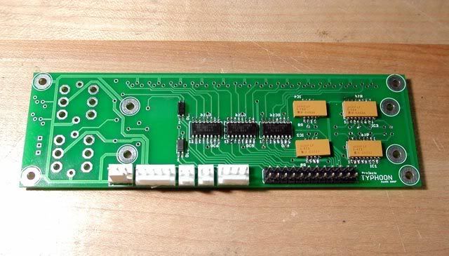
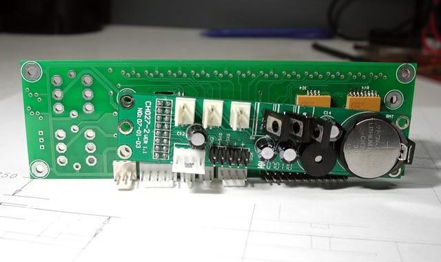
I made some more progress with this front panel. Those surface mount components are actually not as difficult to mount as I first thought. One or two of them could've gone down a little straighter, but for my first go around at it, I'll take it! Of course, all celebrations are on hold until the circuit actually works ...
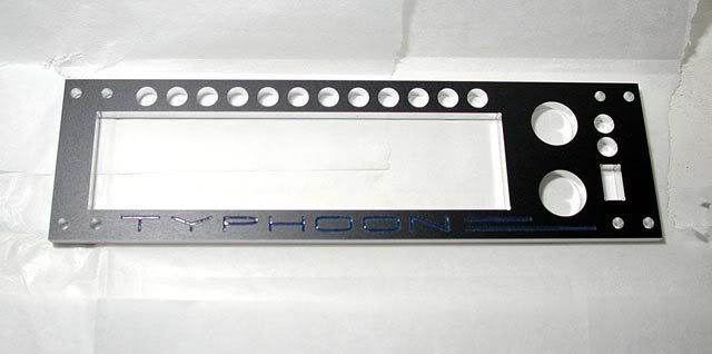
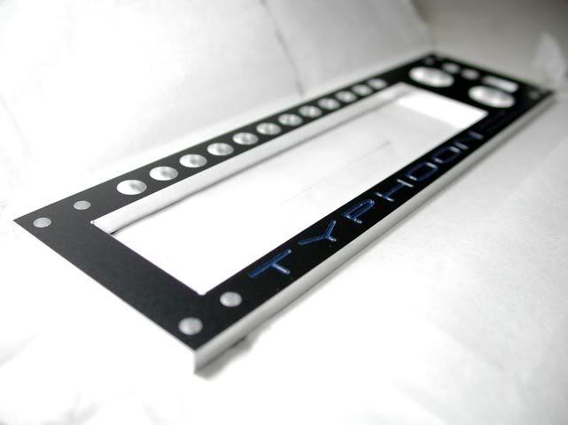
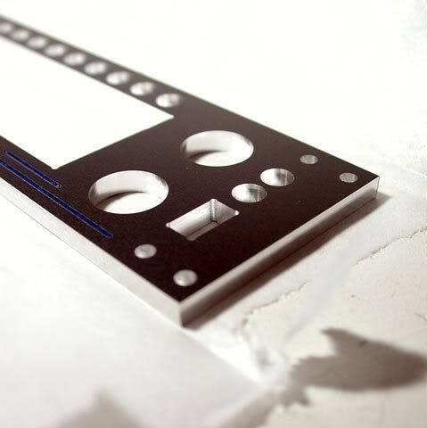
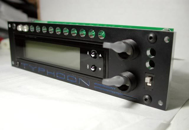
The rest of the pieces (except for the switches) have to be mounted at a specific height, so I figure might as well get the panel done first. craigbru had the front panel for his LOSIAS project done by FPE which turned out awesome, so I thought I'd see what they're all about. Here it is in their free software...
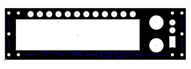
It's also going to need sides, so I might just have all three pieces done at a local machine shop. Either way, here it is assembled...
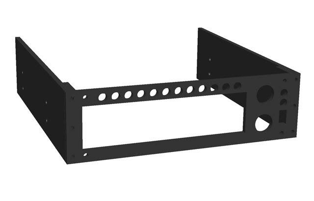
That's it for now, enjoy the weekend!
Of course, all celebrations are on hold until the circuit actually works ...
The rest of the pieces (except for the switches) have to be mounted at a specific height, so I figure might as well get the panel done first. craigbru had the front panel for his LOSIAS project done by FPE which turned out awesome, so I thought I'd see what they're all about. Here it is in their free software...
It's also going to need sides, so I might just have all three pieces done at a local machine shop. Either way, here it is assembled...
That's it for now, enjoy the weekend!
daytripper67mi
Limp Gawd
- Joined
- Feb 22, 2004
- Messages
- 364
speechless and subscribed!!!!!!!!!!!!!!!!!
Justintoxicated
[H]F Junkie
- Joined
- Apr 10, 2002
- Messages
- 14,519
I find it extreamly hard to believe, and disturbing that you can do all this extremaly technical stuff and pay so much attention to detail, Cad Designs, Getting perfect aluminum bends etc, but not know how to polich that aluminum stock.
Your kidding right? Oh yea how are you getting those perfect Bends with that thick aluminum, you can't be getting those perfect bends fromt hat bunch vice alone?
Very good attention to detail here you have one of the most complicated stackers I have sceen and you have managed to cram a TON of stuff into it!
I find it extreamly hard to believe, and disturbing that you can do all this extremaly technical stuff and pay so much attention to detail, Cad Designs, Getting perfect aluminum bends etc, but not know how to polich that aluminum stock.
LOL It's true. I've never polished aluminum. Well, I tried once on an old motorcycle clutch cover, but it didn't work so well.
I think I even have the mother's polish that warmace recommended, but I've yet to get try it on any of these brackets.Your kidding right? Oh yea how are you getting those perfect Bends with that thick aluminum, you can't be getting those perfect bends fromt hat bunch vice alone?
Yep, believe it or not, it's just the vice and a hammer. But there's a trick to getting the same bends everytime:
- Determine the before and after measurements of the bend (or the "developed length" of the bend) with a piece of scrap that has a clean, square edge.
- Measure in 1/2" or so, mark it square, and take note of the exact distance from the mark to the edge.
- Mount the piece in the vice taking care that it's perfectly lined up with the mark and perpendicular to the jaws (I use a combo square for this).
- To bend it, keep a steady force on the free end, and with a hammer, tap the piece right near the bend until it reaches 90 degrees ( or whatever angle you need). During the bend, throttle the force on the free end to help the piece through the bend, but not so much that the free end also bends. This way all the bending happens right where you want it - at the jaw line. Also, depending on how wide the stock is, you may need to tap with the hammer evenly across the piece to get it to bend squarely.
- Measure the distances from the mark to the inside and outside surfaces of the bend. For a 90 degree bend, the inside distance should just be the inside bend radius, and the outside distance the inside bend radius + the thickness of the material. The difference between the two = the developed length.
- Now, let's say you need a "U" bracket to fit exactly into a 3" opening and have 2" legs on each side. To achieve that, place a mark at 2" minus the inside bend radius and bend it. Then measure from the outside face of the first bend to 3" minus the developed length and bend it. Finally, cut the other leg to 2". Voila!
Very good attention to detail here you have one of the most complicated stackers I have sceen and you have managed to cram a TON of stuff into it!
Thanks! I thought at first there'd be plenty of room, but I'm slowly learning how wrong I was!
Mr. G, thanks for the compliment. I think I'm in very good company
Yes indeed you are.
I love it.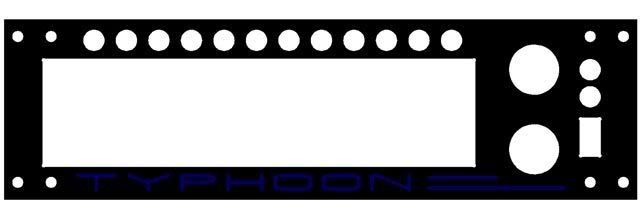
Justintoxicated
[H]F Junkie
- Joined
- Apr 10, 2002
- Messages
- 14,519
Polishing:LOL It's true. I've never polished aluminum. Well, I tried once on an old motorcycle clutch cover, but it didn't work so well.
Yep, believe it or not, it's just the vice and a hammer. But there's a trick to getting the same bends everytime:It usually takes me a bend or two to start getting consistent bends. Also, if you have more than one piece to bend, it helps to draw out a template and mark the pieces off it instead of off a ruler every time.
- Determine the before and after measurements of the bend (or the "developed length" of the bend) with a piece of scrap that has a clean, square edge.
- Measure in 1/2" or so, mark it square, and take note of the exact distance from the mark to the edge.
- Mount the piece in the vice taking care that it's perfectly lined up with the mark and perpendicular to the jaws (I use a combo square for this).
- To bend it, keep a steady force on the free end, and with a hammer, tap the piece right near the bend until it reaches 90 degrees ( or whatever angle you need). During the bend, throttle the force on the free end to help the piece through the bend, but not so much that the free end also bends. This way all the bending happens right where you want it - at the jaw line. Also, depending on how wide the stock is, you may need to tap with the hammer evenly across the piece to get it to bend squarely.
- Measure the distances from the mark to the inside and outside surfaces of the bend. For a 90 degree bend, the inside distance should just be the inside bend radius, and the outside distance the inside bend radius + the thickness of the material. The difference between the two = the developed length.
- Now, let's say you need a "U" bracket to fit exactly into a 3" opening and have 2" legs on each side. To achieve that, place a mark at 2" minus the inside bend radius and bend it. Then measure from the outside face of the first bend to 3" minus the developed length and bend it. Finally, cut the other leg to 2". Voila!
Thanks! I thought at first there'd be plenty of room, but I'm slowly learning how wrong I was!
- I just sand aluminum with 400 then 600 (or just 600).
- Next, using a buffing wheel from lowes or HD, and some white rouge, turn on the buffing wheel, apply the rouge.
- Hold object to be polished against the outer corner, and viola mirror reflective aluminum.
Mothers is best for polishing things that are already polished
It takes forever by hand otherwise. You can use a drill press for polishing as well. I don't have a machine in my room, so no more polishing for me...I read your post above 3 times and I'm still totaly lost. Not sure what a you mean by a bend radius, or marking the scrap and putting it in the vice perpendicular to the mark?
Actualy you lost me on step 2...I'm pictuing drawing a straight line on a piece of aluminum (say a piece of aluminum strip/bar) from one side to the other. Sticking it in the vice so the mark is parallel to the jaws (you said perpendicular but I don't understand how to do that and still get a good grip). Do you mean like put the sides of the aluminum strip in the vice? If so I don't see how you could hammer it into shape?
Ok so I mark something and bend 90 deg, clamp it in the vice and hammer it flat down to the jaws (for 90deg) then take measurements? haha yea I'm lost..
It's ok though since I no longer have access to a bench vice, all my moding has to happen in the driveway or lawn area now with no vices or anything...Someday I will own a house, I just need 200k a year here in cali to even consider it.
One more thing; does the quad rad have more performance than the Thermochill PA 120.3?
Mothers is best for polishing things that are already polished
Oh, now I know why it didn't work!
lolOk so I mark something and bend 90 deg, clamp it in the vice and hammer it flat down to the jaws (for 90deg) then take measurements? haha yea I'm lost..
Basically, what you're after is the developed length of the bend. With a piece of scrap, you can determine the developed length experimentally by measuring first, bending it, then measuring again. The difference is the developed length. When that bar bends, it stretches some amount, which is mostly dependent on the type and thickness of the material. You can use the developed length to determine exactly where to mark other pieces so that the finished dimensions are predictable.
When the bar bends, there's always some "round" left at the inside corner. That small little round is the inside bend radius. If the piece was bent exactly from the mark, the inside bend radius should be the distance from the mark to the inside surface of the bend (for a 90 degree bend).
For step two, see if this helps:
2. Measure in 1/2" or so, mark it square (perpendicular across the bar), and take note of the exact distance from the mark to one end.
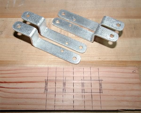
Those dark marks near the bends are from the hammer ... oh, look there's the hammer and square right there on the bench...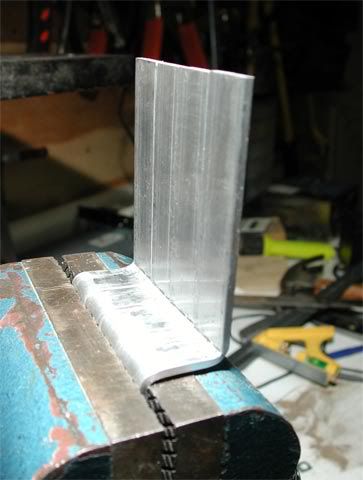
Those are the lines I keep referirng to. These were actually bent one at a time, then mounted all together to "tweak" them into alignment.
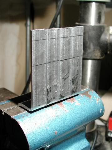
Here's the template I used to mark the bends on each piece...
One more thing; does the quad rad have more performance than the Thermochill PA 120.3?
That I don't know. I've read the 120.3 has less pressure drop. I'll have some temperatures posted eventually...
Nicepants42
Gawd
- Joined
- Aug 30, 2004
- Messages
- 772
I've read at Procooling that the PA120.3 has less pressure drop, and out-performs the GTX480 with low rpm fans. I believe it was said that with higher rpm fans, the GTX480 was slightly superior. (Basically, the PA120.3 has less air-flow and water-flow resistance, so it takes less fan and pump power to make it perform.)
In a case like this where the fans are not low-rpm, and are set up in push-pull, the GTX480 should out-perform the PA120.3 by a handy margin since air pressure is not an issue. If you don't have to worry about air resistance, all that's left is surface area and water pressure drop; the GTX480 wins big in surface area and only gives up a little with water pressure drop.
If we were going for silence rather than balls-out push-pull performance, the PA120.3 would be the better choice.
Citizen _insane
Gawd
- Joined
- May 2, 2006
- Messages
- 565
Extremely impressive. I've spent the last half hour going through the whole thread and I'm amazed at your attention to detail. Keep up the good work
btw - if you don't mind, how much did those custom PCB's cost? If they're not too bad, I might use that company for printing custom amplifier boards.
btw - if you don't mind, how much did those custom PCB's cost? If they're not too bad, I might use that company for printing custom amplifier boards.
I've read at Procooling that the PA120.3 has less pressure drop, and out-performs the GTX480 with low rpm fans. I believe it was said that with higher rpm fans, the GTX480 was slightly superior. (Basically, the PA120.3 has less air-flow and water-flow resistance, so it takes less fan and pump power to make it perform.)
Yup, that's an excellent summary of the comparison. I wanted as much surface area as I could get to hopefully keep it as quite as possible, but still get excellent cooling. But the GTX480 doesn't flow air quite as easy as the 120.3, so how do you solve that? 7 120mm low-speed fans!
In a case like this where the fans are not low-rpm, and are set up in push-pull, the GTX480 should out-perform the PA120.3 by a handy margin since air pressure is not an issue. If you don't have to worry about air resistance, all that's left is surface area and water pressure drop; the GTX480 wins big in surface area and only gives up a little with water pressure drop.
Actually, I'm pretty sure those Yate Loon fans are the low-speed variety. Even with a full 12V, one can hardly be heard - to the point where the fan controller is almost not needed. When I bench tested the rad with all 7 fans, I was quite pleasantly suprised at how quiet they were even while push/pulling a healthy amount of air through the rad. The temperatures will tell the rest of the story once I get it running.
If we were going for silence rather than balls-out push-pull performance, the PA120.3 would be the better choice.
I don't know - even with 7 fans, it's just a whisper. I don't know yet how it cools though.
how much did those custom PCB's cost?
Thanks! The PCB was I think around $34 shipped. I ordered one but they printed and included two! I also looked at pcbexpress, but they wanted I think $50 for a minimum quanity of 3, and they didn't come with the solder mask or silkscreen which BatchPCB includes on BOTH sides. I have to say, it's a really impressive service with an awesome price.
Justintoxicated
[H]F Junkie
- Joined
- Apr 10, 2002
- Messages
- 14,519
Man If I had your skillz I would have my own side buisness right now. I actualy have had something in the works for 3 years that requires bending sheet metal, and an SMT Circuit.
I had someone bend the metal for my prototype and used Pin Through components and made a cheap circuit (Actual ynot much cheaper than doing it the right way)...
Oh well that stuff is too complex for me to understand and model etc...I already wasted a good chunk of my free time trying to learn it on my own.
I still don't follow your bending tutorial but I bookmarked it...
What program are you using to model the circuits?
Bend Radius is the thickness of the metal at the bend then?
Well keep up the good work, that custom Panel is really nice, about 100,000 times more complex than the simple regulator I was trying to design to control Current and filter spikes...I'm jealous of your knowledge both in making perfect bends, and in circuit design.
For me I just bend stuff with pliers and channel locks, but if I did have a bench vice I would just bend stuff over and over untill I ended up with something that fits. but like they say, nothing is hard, IF you have the right tools (And I do not).
I can't even fit the stock hard Drive cage AND a 120x2 mm radiator in my stacker!
The next step in this front panel sub-project is to cut a hole in the custom PCB for the Logisys connector to pass. After drilling a few holes, I ended up passing a coping saw through the hole to rough it out...
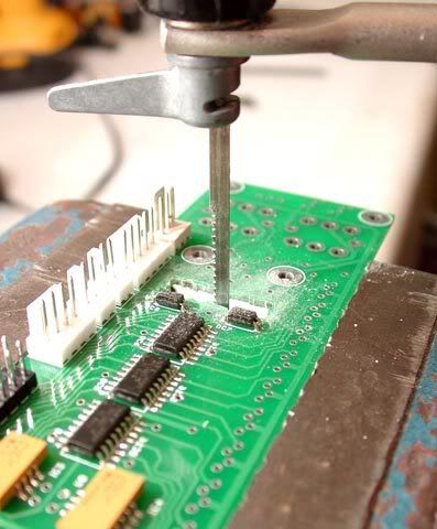
...and then cleaned it up with a file...
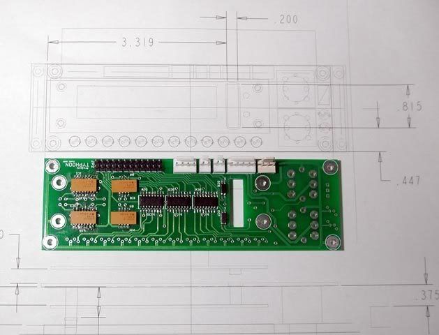
The dimensions came from a printout of the layout. I realized after starting to mark it that those dimensions should've been to the HOLE instead of the connector... I hate it when I have to do math in my head!
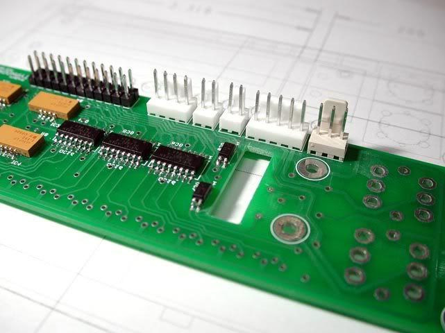
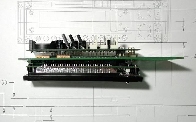
I took some pics of the first test fit. Looks like the hole at least line up, so that's good...
Here's how it looks from the top. Next thing to do is cut some standoffs...
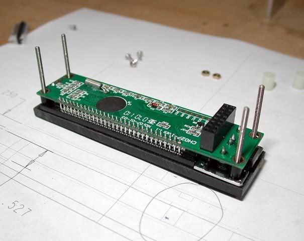
I printed another drawing with dimensions for the standoff heights, and then carefully cut them to length...
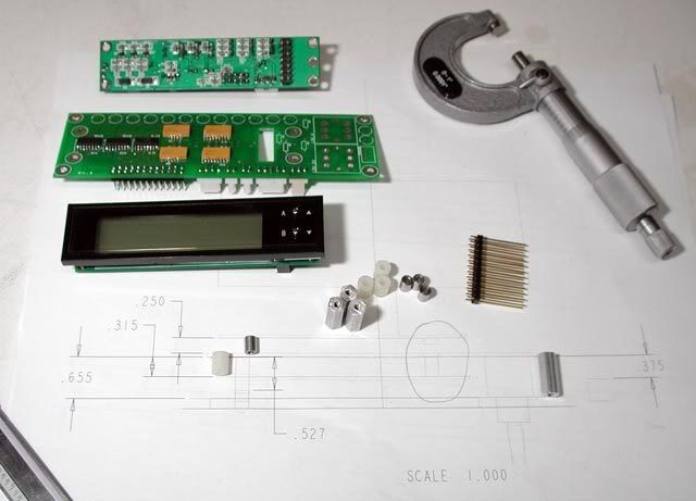
Here are the standoffs in place over the drawing. With those large toggle switches in there, the original header on the Logisys daughter board isn't long enough to reach the connector (check the gap circled in pencil). That's the reason for that wire-wrap header: it's going to replace the header on the daughter board...
I wish I had more, but it's all I have for now. There's a few more things to do, then the front panel should be done:
...and then cleaned it up with a file...
The dimensions came from a printout of the layout. I realized after starting to mark it that those dimensions should've been to the HOLE instead of the connector
... I hate it when I have to do math in my head!
I took some pics of the first test fit. Looks like the hole at least line up, so that's good...
Here's how it looks from the top. Next thing to do is cut some standoffs...
I printed another drawing with dimensions for the standoff heights, and then carefully cut them to length...
Here are the standoffs in place over the drawing. With those large toggle switches in there, the original header on the Logisys daughter board isn't long enough to reach the connector (check the gap circled in pencil). That's the reason for that wire-wrap header: it's going to replace the header on the daughter board...
I wish I had more, but it's all I have for now. There's a few more things to do, then the front panel should be done:
- Find a 1" screw that'll thread into the original holes at the back of the Logisys panel.
- Swap the header on the daughter board for the new one.
- Solder the rest of the PCB components to height.
- Make the left and right sides.
- Test
- Assemble!
omegatotal
Gawd
- Joined
- Mar 15, 2002
- Messages
- 672
NOICCEE!!!
thorton3100
n00b
- Joined
- Feb 8, 2007
- Messages
- 29
Cool!!Moder Pro
To k00lance, it'll mount to the case with these...
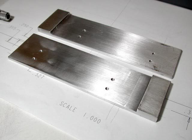
Greg at a local machine shop made them up for me over the weekend. They fit perfectly and his fee was unbeatable. All I did was send him a dimensioned drawing, and he had them ready the next day. Thanks Greg!
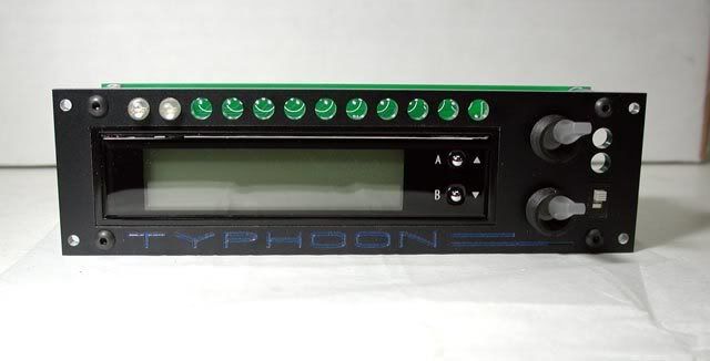
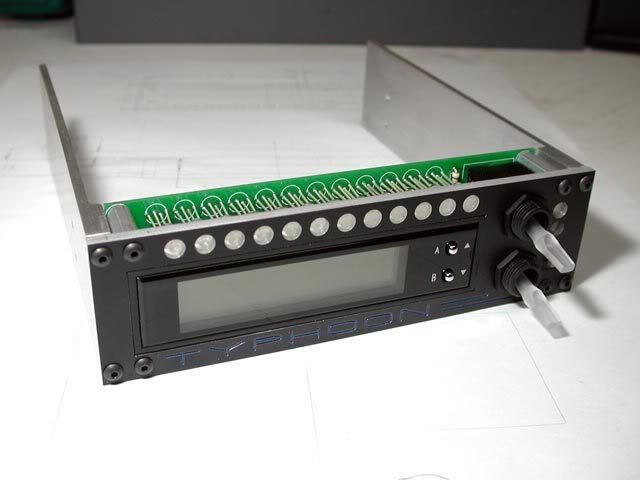
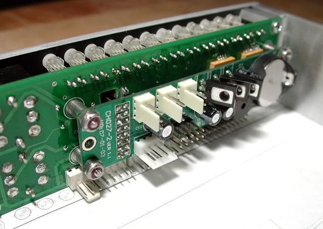
Here's how it looks now assembled and fully soldered...
The header on the daughter board is replaced, but I still have to find the 2-56 x 1.25" screws to mount it. I was hoping to find them at a local hardware store, but no luck...
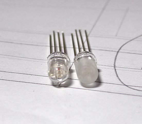
Btw, the LEDs were "diffused" using a Dremel and a wire brush bit...
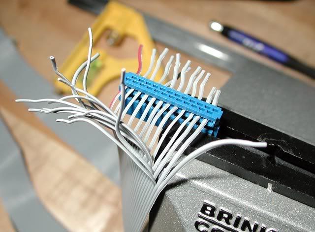
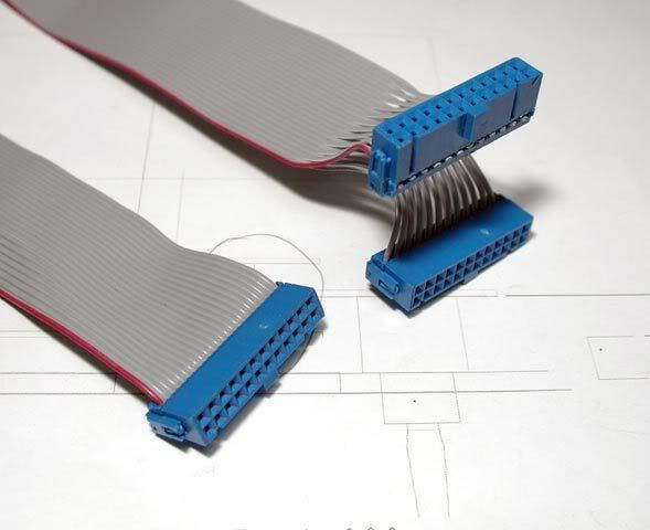
The next step was to start building the wires. I went with a ribbon cable to make the connection between the LED headers on the RAID card and the front panel. Having the ribbon cable makes it a lot easier to build compared to crimping connectors to individual wires, but even then, it was still quiet a tedious job!...
Here's the light switches lit up...
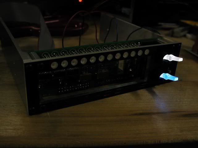
And then the moment of truth came!... Is it actually going to work? Yup! (almost ) Out of the 24 drive leds (12 activity and 12 vault), 7 of them didn't work. I was concerned at first that I had fried a component or two during the soldering, but after poking around with the tester for a bit, I discovered it was just a few of the legs didn't fully solder to their pads (it's no surprise ). After fixing those, all was good! It's a little hard to watch because of the quality, but anyway here's a video taken from my cell phone while it boots...
Greg at a local machine shop made them up for me over the weekend. They fit perfectly and his fee was unbeatable. All I did was send him a dimensioned drawing, and he had them ready the next day. Thanks Greg!
Here's how it looks now assembled and fully soldered...
The header on the daughter board is replaced, but I still have to find the 2-56 x 1.25" screws to mount it. I was hoping to find them at a local hardware store, but no luck...
Btw, the LEDs were "diffused" using a Dremel and a wire brush bit...
The next step was to start building the wires. I went with a ribbon cable to make the connection between the LED headers on the RAID card and the front panel. Having the ribbon cable makes it a lot easier to build compared to crimping connectors to individual wires, but even then, it was still quiet a tedious job!...
Here's the light switches lit up...
And then the moment of truth came!... Is it actually going to work? Yup!
(almost ) Out of the 24 drive leds (12 activity and 12 vault), 7 of them didn't work. I was concerned at first that I had fried a component or two during the soldering, but after poking around with the tester for a bit, I discovered it was just a few of the legs didn't fully solder to their pads (it's no surprise ). After fixing those, all was good! It's a little hard to watch because of the quality, but anyway here's a video taken from my cell phone while it boots...Emission
Supreme [H]ardness
- Joined
- Dec 6, 2005
- Messages
- 4,420
It's interesting how the hard drives are accessed in a row like that , very cool indeed.
, very cool indeed.0ptional
Don't Trust Your Friends with Your Decanter
- Joined
- Feb 22, 2003
- Messages
- 5,593
SUBSCRIBED!
That panel is all kinds of awesome...
That panel is all kinds of awesome...
Bah! Lost a few updates. I deserve it for posting during the database move and not backing it up! Anyway, this update is only a summary of those other lost updates (rip)...
First, I finished off the custom front panel with some 2-56 threaded rod to assemble the daughter board...
Front panel DONE!! (except for the cables)...
I'm going to flip the PSU so it's fan-down. In that case, I'm going to need some holes in the mobo tray to pass the PSU cables...
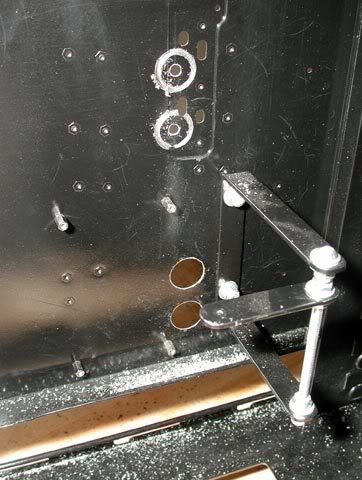
Holes completed...
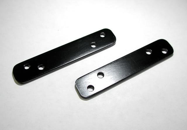
A new bracket template to flip the PSU:
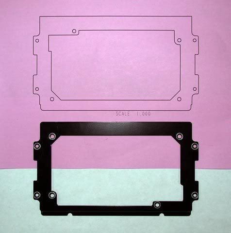
Formed and cut...
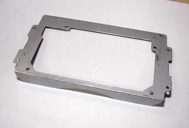
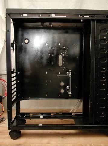
Painted and mouted...
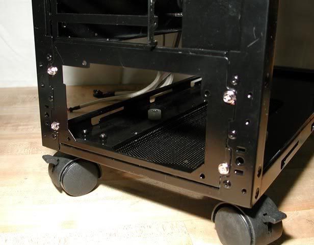
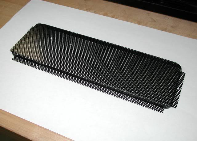
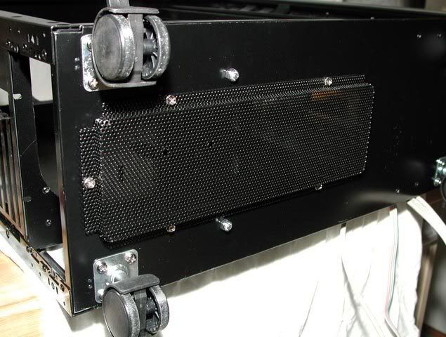
Bottom vent cover painted...
and mounted to the bottom to allow the PSU fan to breath better and to allow the pump to sit lower (more on that)...
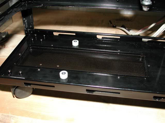
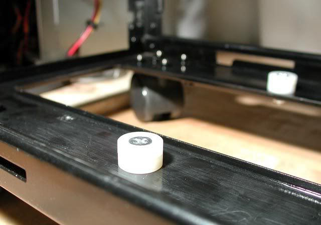
Placed some nylon spacers to take the place of the vent cover to support the PSU...
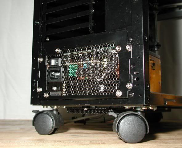
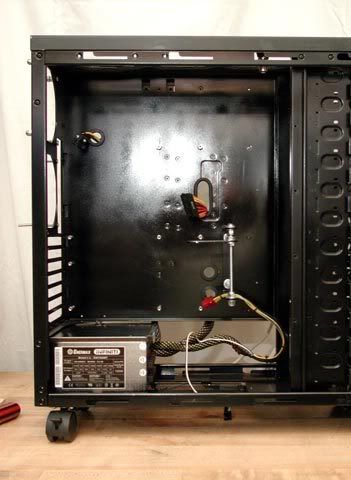
PSU installed...
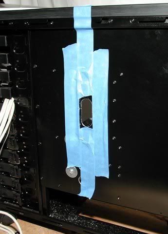
PSU power cables now run behind the mobo tray...
Anyway, this update is only a summary of those other lost updates (rip)...First, I finished off the custom front panel with some 2-56 threaded rod to assemble the daughter board...
Front panel DONE!!
(except for the cables)...
I'm going to flip the PSU so it's fan-down. In that case, I'm going to need some holes in the mobo tray to pass the PSU cables...
Holes completed...
A new bracket template to flip the PSU:
Formed and cut...
Painted and mouted...
Bottom vent cover painted...
and mounted to the bottom to allow the PSU fan to breath better and to allow the pump to sit lower (more on that)...
Placed some nylon spacers to take the place of the vent cover to support the PSU...
PSU installed...
PSU power cables now run behind the mobo tray...
Over the weekend I built my new rig in a CM Stacker orig, so this build is wayy more appealing now. I assembled it to test the higher-performance parts but will disassemble it to WC once all the parts come in.
I'm seriously considering painting the inside of the case a matte black, any recommendations?
As well, are you going to use the USB ports from the stock front panel? If you are you might find the cables a little too short to span accross the case to the bottom left of the mobo. Yet as I'm typing this I'm remembering the rad in the top bay meaning if you keep the panel it wont be there blahblah blah
COOL!
I'm seriously considering painting the inside of the case a matte black, any recommendations?
As well, are you going to use the USB ports from the stock front panel? If you are you might find the cables a little too short to span accross the case to the bottom left of the mobo. Yet as I'm typing this I'm remembering the rad in the top bay meaning if you keep the panel it wont be there
blahblah blahCOOL!
Yet as I'm typing this I'm remembering the rad in the top bay meaning if you keep the panel it wont be there
Yes, I'm using the stock I/O panel. And, you're right: it'll get mounted about 5 bays down from the top. From there, the USB cable reaches the header without a problem. I'm going to route it from the panel, out the hole in the side of the bay, behind the mobo tray, and then through the hole I cut there.
I'm seriously considering painting the inside of the case a matte black, any recommendations?
If I was going to paint another case, I'd start with etching primer which is something I didn't use. The paint job I did is ok (it's functional and doesn't flake), but it could be better. For example, the clear coat I used scratches too easily (needs to be harder). Also, I've since read somewhere that among the spray-can paint, Rustoleum is better than Krylon. Other than that, I don't have any solid recommendations, but there's lot of guides out there on the subject, I'm sure.
Recovery update summary #2:
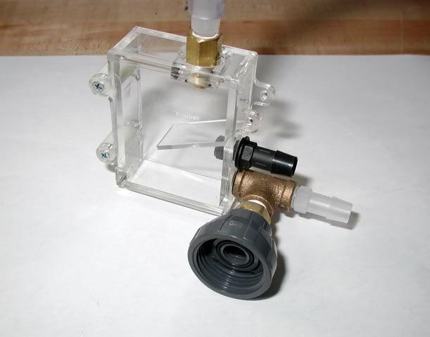
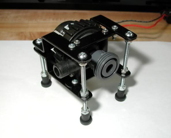
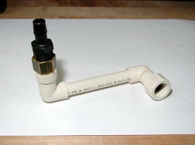
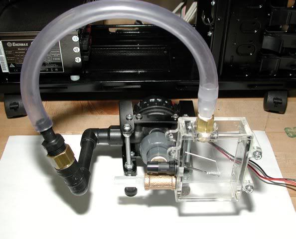
I ordered the 1/2" threaded pump housing from Laing (bottom left)...

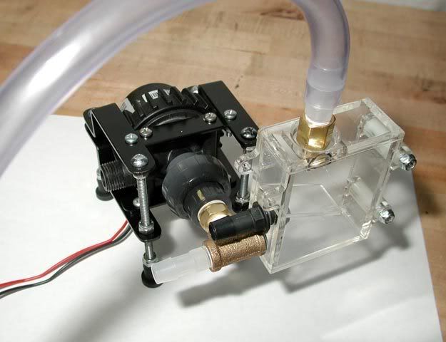
Having the threaded inlet, a PVC union can be used to connect the res...:
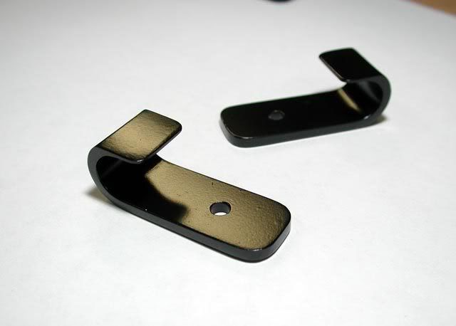
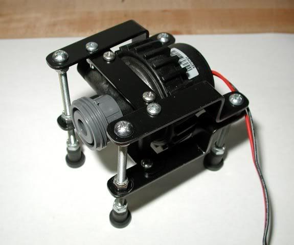
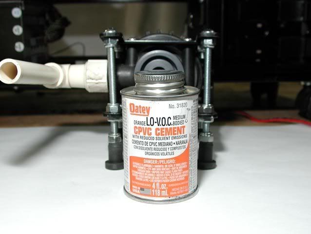
But that big nut on there didn't fit in with the original pump mount, so two more brackets fixed the problem by spreading the legs further apart:
Painted the res hanger while I was at it...
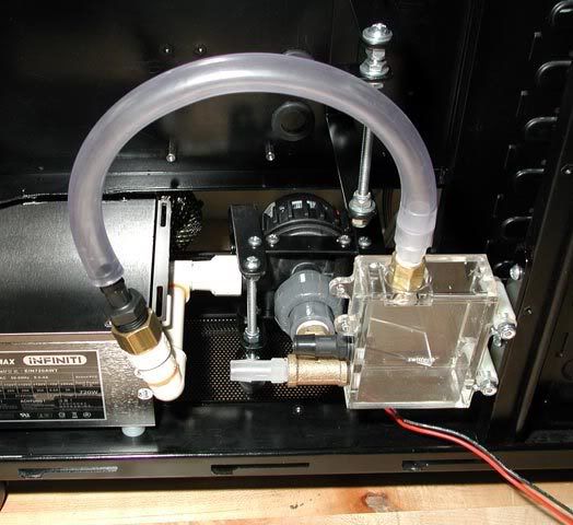
Pump mount with pump looks like this now...
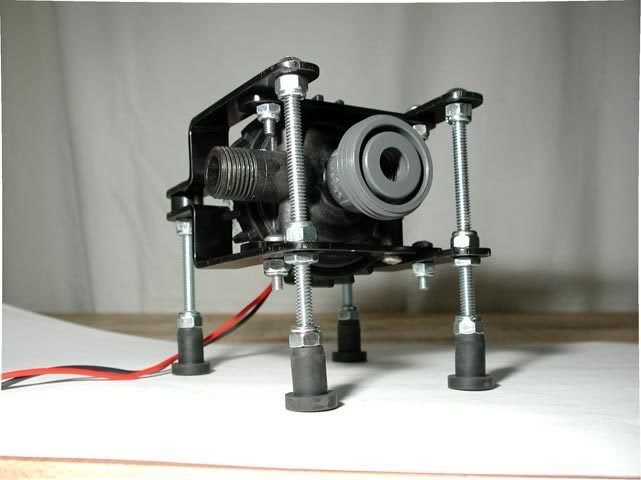
The StarWars shot...
Assembled...
and fit into the case...
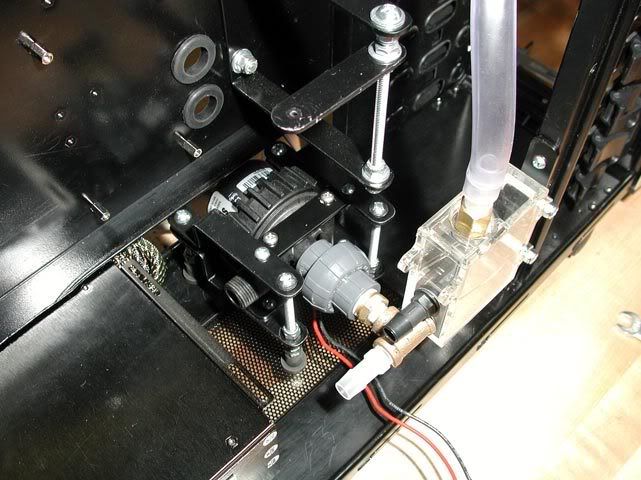
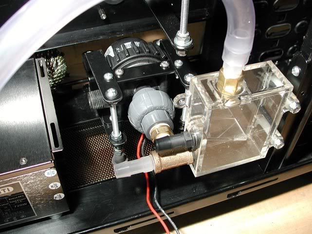
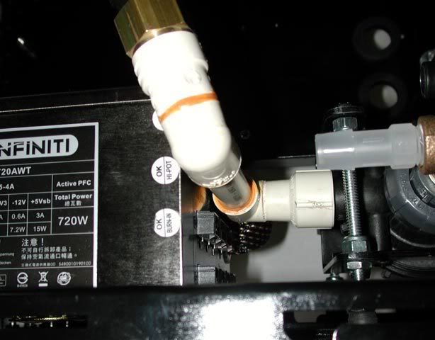
The outlet is actually a straight thread, which made finding a fitting a problem. Finally, Lowes had CPVC fittings which fit perfectly...
It's a very tight fit...
Painted up and ready...
That's it for the lost updates. I've done a lot with the project since a few days ago, so the next update will be new. Thanks for looking!
I ordered the 1/2" threaded pump housing from Laing (bottom left)...
Having the threaded inlet, a PVC union can be used to connect the res...:
But that big nut on there didn't fit in with the original pump mount, so two more brackets fixed the problem by spreading the legs further apart:
Painted the res hanger while I was at it...
Pump mount with pump looks like this now...
The StarWars shot...
Assembled...
and fit into the case...
The outlet is actually a straight thread, which made finding a fitting a problem. Finally, Lowes had CPVC fittings which fit perfectly...
It's a very tight fit...
Painted up and ready...
That's it for the lost updates. I've done a lot with the project since a few days ago, so the next update will be new. Thanks for looking!
Emission
Supreme [H]ardness
- Joined
- Dec 6, 2005
- Messages
- 4,420
The setup and ideas are looking great. Sometime by the end of the year I'll be starting a project of my own that could be similar to this .
.