Project: TYPHOON (Stacker+ GTX480) **2010 REBUILD**

UPDATE: Custom D5 Pump Mount

I made some progress, but it seems the list left to be done grew! :(

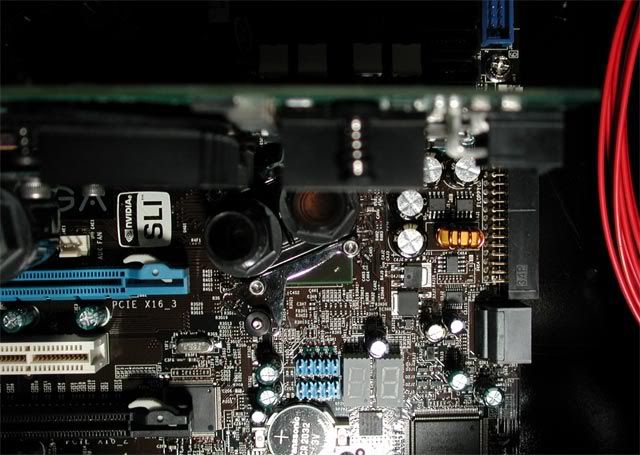
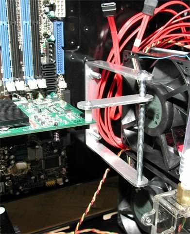
This is a previous picture showing how the pump was mounted before...
0610.jpg


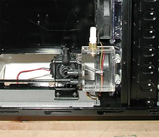
The problem with it not aligning with the res is now fixed (hopefully) by the shorter brass res fitting. The next problem I realized is that even if the pump could move all the way to the right against the fan, the outlet would run right into the longer 8800 graphics card, (I don't have one yet, but I might in the future). The solution would be to rotate the pump 90 degrees and run the outlet tube to the left.

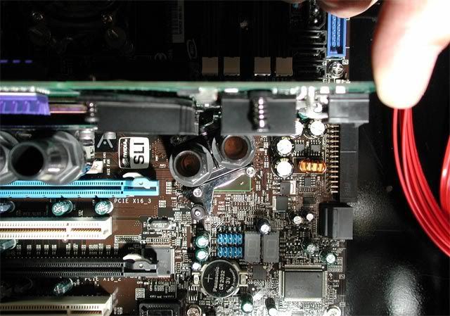
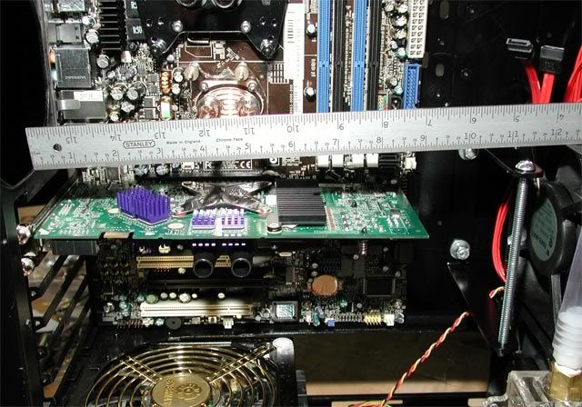
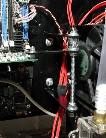
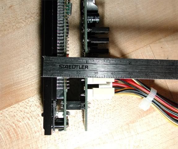
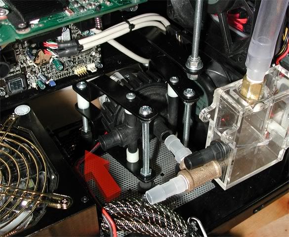
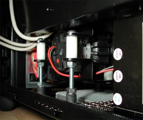
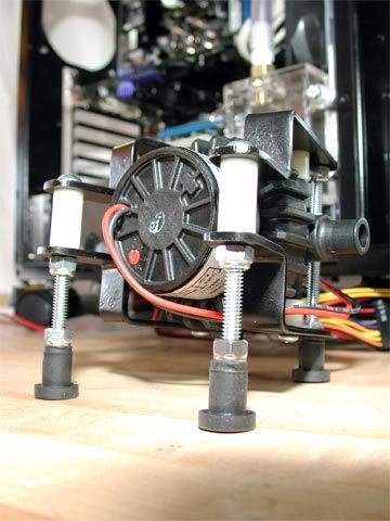
Well, here's how the pump looks now mounted in its new mount. With the shortened res fitting, the pump moved the right and opened up enough room for the outlet tube to route horizontally toward the PSU. The red arrow points to the gap where it would route. Now the problem is: that gap's a little too tight for 1/2" ID tubing to make the bend. I need to find a way to put a threaded 90 degree elbow on the end of that outlet barb. Hmmm... Anyone have any suggestions?...
1020.jpg


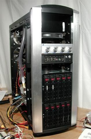
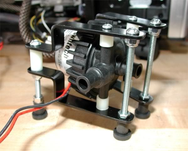
This time, the pump is not bolted to the case. Instead, it just sits in there which makes it easier to line the pump up with the res...
1030.jpg


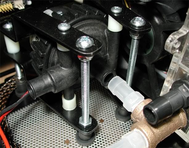
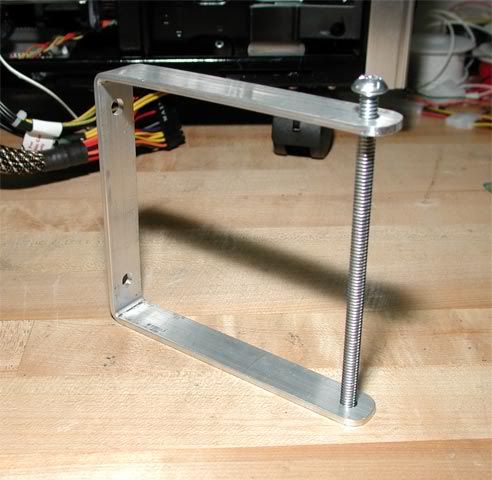
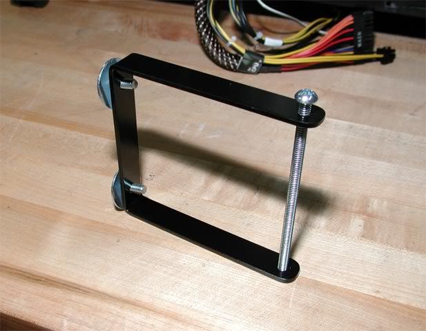
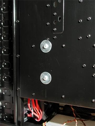
How it looks from the back side. The rear legs can be adjusted up/down for inlet barb alignment...
1040.jpg


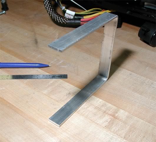
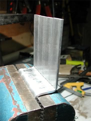
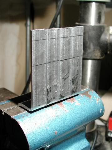
And some pics of the making in progress. Actually each piece was bent individually, then placed altogether and "tweaked" until they were the same...
1060.jpg


1050.jpg


The pieces were measured and bent off one template for consistency. Here they are power sanded and ready for paint...
1070.jpg


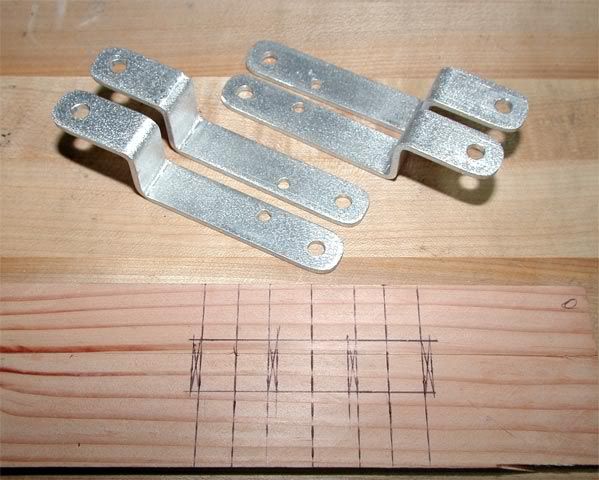
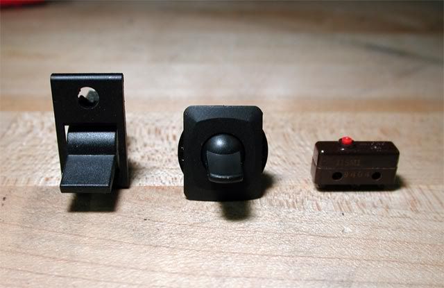
The feet are 1/4-20 "well nuts" which should keep any pump vibrations away from the case...
1080.jpg


1090.jpg


More to come...
 
UPDATE: Adjustable Card Holder

This update is all about this picture of the graphics card sagging down over the barbs of the south bridge water block...
1100.jpg


Here's how it needs to look in order to prevent the graphics card from pressing against the south bridge block via the tube coming in and potentially cause problems down the road...
1110.jpg


Basically, all that's needed is upward force at the corner of the card. To provide the force, I came with an "adjustable card holder" that started like this...
1120.jpg


It bolts to the motherboard wall of the case...
1130.jpg


Here's a test fit before painting. It's tall enough to accomidate up to three cards I think...
1140.jpg


Ready to install...
1150.jpg


The location of the mounting holes were picked to give at least enough room for the largest graphics card, currently the 8800GTX at 10.5", and still provide enough room between the fans to pass wires, etc...
1160.jpg


1170.jpg


How it looks from the back...
1180.jpg


Fully installed. I plan to make a new arm as needed to fit the next card upgrade, though it probably won't be for a while...
1190.jpg


That's all for now. I hope you enjoy it. The next update will start in on a custom drive bay panel to show HD activity and temperature measurements.
 
UPDATE: Front Panel (part 1)

This idea of a custom front panel started because for whatever reason, the Supermicro drive enclosures don't have fault lights (?). The enclosures have the light pipes in there, but there's no LED on the board to light them. Well anyway, since the RAID card has headers for them (and for the activity lights too, see here for a pic of the card), then I figure might as well move all the lights to a front panel, and add a few more things while I'm at it, namely:
  • Hard drive activity and fault lights for 12 drives
  • Temperatures from two spots in the water loop.
  • Fan speed display (optional)
  • Light switches
  • BIOS reset switch
It just so happens that the only open drive bay left is right in front of the res, and 2" of it are still usable - perfect!...
0710.jpg


Here's how the proposed panel will looked mocked up with Photoshop. The bays above and below the front panel will have the stock stacker bay covers so that air can pass through the front portion of the rad...
1270.jpg


My idea is to use a Logisys FP206 "Digital Thermal Controller" panel to display the temperatures and fan speeds, and to build a PCB for the hard drive LEDs. Here it is in the box...
1200.jpg


It comes in a 3.5" case...
1210.jpg


But most of it is empty space...
1220.jpg


There's basically two boards connected through an interface. I'm thinking to stack another board for the hard drive LEDs...
1230.jpg


The two boards already use up most of the available 2", but I think there's enough room to squeeze another board in there (hopefully!) :(...
1250.jpg


And finally, here are the switches I picked for the job. The left and middle are for the lights, but I haven't decided which one to go with yet. Either way, there'll be a pair of them for two sets of lights, UV and white. The left switch already has a spot for a blue LED, but the styling of the middle switch I like a little better. The right switch is a momentary SPDT. I plan to connect it to the CMOS reset header on the mother board and install it just below the surface of the front panel so that it's only accessible with a paper clip.
1260.jpg


For the next update, I'll post some pics of the CAD layout of the front panel. In the meantime, I'm very interested in any thoughts or ideas you have. Thanks for looking! :)...
 
I like your idea for the front bay device :)
 
@ Adidas4275 and FrEaKy, thanks for the feedback! :)

Here's the layout with the round switches. The problem with those switches, is that with two of them together, the flange on the nuts hang out just past the top and bottom edges of the drive bay...
1290.gif


Here's how it looks with the square switches. I think these fit better, plus the LED holder is already done...
1300.gif

More to come...
 
That pump mount looks snug as a bug in a rug', very nice.

I like the middle switch, too bad its a tad too big.
 
Wow it is looking great, keep it up, can't wait to see it finished. I like the card supporter.
 
good job on the custom pump mount. Its simple but is really flexable to many different types of mods.
 
Thanks everyone for the feedback! :)

That pump mount solved one problem, but presented another. I've been wondering how I can put a 90 degree fitting right there between the pump's outlet and the PSU. I've seen pictures of the pump with custom fittings on the barbs, but I don't know how they do it. Got any ideas?
 
i dont think ou cant do it with the d5 because it seems the barbs are custom molded with the pump as one big plastic shell. if i am wrong, then if you twist hard enuf you can unscrew it, but i dont think you can. your best bet would be to get an elbow fitting and just use as little tubing as possible.
 
amoeba1126, you are definitely correct. Those barbs are molded in with the rest of the housing. It seems Laing makes other housings for the D5 pump though. That threaded one looks interesting, but it I'm afraid after adding a 90 degree fitting to it, it'd run into the PSU...
PumpHousing.jpg
 
what you CAN do is mebbe use a dremel and actually CUT about half an inch off the barb off and do the same with the barb on the elbow fitting. this way you save between the two fittings about an inch. if you mess up, you can always order another housing from Laing, so really, you got nothing to lose :D
 
for the first method, i recommend using masterkleer and boiling water as well as zipties, because after you cut it off, you may not have enuf clearance on the barbs for a normal worm clamp.
 
I like the idea of making the barbs shorter. How/where do I order another housing, just in case I screw this one up?
 
I drew up a schematic of the hard drive activity LED circuit...
1310.gif


Basically, there's 12 bi-color LEDs across the top: green for activity and red for fault. The fault and activity headers on the raid card connect to the board via a pair of 24 conductor ribbon cables.

Since there are no fault LEDs in the Supermicro enclosures (what's up with that?), the fault connector routes directly to the red side of the LEDs.

But there are activity LEDs on the enclosures, so I figure might as well drive them from here too. To do that, the signal would have to either be split, making the LEDs dim OR relayed, making the LED voltage controllable via a resistor. I picked the later and found the ULN2801 NPN transistor array to relay the activity signals from the raid card to both the enclosures and the front panel.

Next thing to do is determine which resistors to use, then after that, layout a PCB, then after that, make it! :D It'll be my first one, so I'm sure it'll be interesting... :)
 
Are you etching the PCB or are you going to use a prototype breadboard?

Protoboards are much better than even good quality etchings IMO. A bit more work to solder, but they're smaller and less prone to trace burnoff (I've literally had traces flake off an etched PCB before... about 4 months into service! :mad: )
 
@ tylerdustin2008, thank you!

@ Arcygenical, thanks for the info. Flaking traces would not be good!

I'm going to try and avoid etching one myself. I've not done it before and from the guides I've seen around on the net, it looks like it'd take me a while to get one right (if ever).

When you say a prototype breadboard, do you mean one like this from RadioShack? That one would probably work just fine, except I'm not sure how I'd solder all those criss-cross connections.

The other option is to have it made. ExpressPCB has their mini board, but it's too small for what I need, plus it doesn't have the mask or silkscreen layers. www.batchpcb.com seems to offer everything to fit perfectly: 2 layer, masking, silkscreen, only one board, and a price that's sounds pretty good. I'd just have to figure out how to create a gerber file to meet their specs.

omg, it's time for sleep. More on this later... :eek: ZZZzzzz
 
I'm going to try and avoid etching one myself. I've not done it before and from the guides I've seen around on the net, it looks like it'd take me a while to get one right (if ever).

When you say a prototype breadboard, do you mean one like this from RadioShack? That one would probably work just fine, except I'm not sure how I'd solder all those criss-cross connections.

That's the board I mean.

About those crisscrosses, all I'd do is use pieces of wire to make the connections, and that way you can crisscross as many times as you want :p. It seems to work better than just soldering to the ring on the PCB. I HATE pcb's sometimes, as the copper rings pop-off when you're working with them.

I've had so many PCB's thrown in the trash... after I'm about 80% done my soldering, a copper ring pops off. Sure, you can normally solder a wire in the PCB trace's place, but that's a hassle on boards without a lot of pinholes.

That company doesn't seem bad. I'd rather do it myself with the protoboard and save the cash, but your time (and since it's your first try, which never really goes that well) might be worth it, with all the other things you've got going on :D

I'd like to make a comment on this work as a whole... You've gotta be one of the most ingenious modders I've seen in awhile... You use a large variety of general parts, and fab lots of custom pieces to overcome difficulties... the solutions damn nice when you're done too. That's the goal of case modding IMO, overcoming difficulty with your own intellect and fabrication skills. Major props to you for getting back to the modding roots, and using your own solutions rather than store bought products.
 
warmace, thank you. I agree, the clips would look a lot better polished. What's the best way to polish them?

The method I would use is find the finest wet sanding paper you can (the smallest i can find is 600grit) and sand away. Then if you have a dremel tool, some hardware stores stock a polishing kit with cloth wheels, and little things of polish.

I myself have a tub of Mothers Aluminum Polish leftover from when i was detailing my motorcycle. A cut-up teeshirt and a little time in front of the TV and you'll be amazed at how well a little elbow grease can go a long way. It, or similar products, can be found in automotive stores or the Auto' section of some super stores.

Leak testing over your power supply would make me cringe, best of luck!


Heres an Image showing how well that board could be criss-crossed 1981 IBM prototype motherboard.
 
Major props to you for getting back to the modding roots, and using your own solutions rather than store bought products.

QFT

Its things like this that sets you ahead of the stock computer owners with deep pockets.
 
@ Ockie, thank you!

@ Arcygenical, what a compliment, thank you!

... after I'm about 80% done my soldering, a copper ring pops off.

I remember those! That's exactly right, just when the board's almost done, one of those rings goes mobile on you.

I actually played around with a layout using a prototype breadboard and a different display panel. Here it is with the LED driver circuit on the left and an Enermax display panel on the right...
1320.gif


I decided to look at a different way when I realized how little space there is in there. I think the Logysis 3.5" display panel will work a lot better because stand-offs can be place around it and then a full-size PCB stacked behind it. Maybe then there'd be enough room to use a prototype breadboard, I'm going to check that out next. That and plus I received a little package from Mouser yesterday that contained the ULN2801 transistor arrays and the LEDs. So also next will be a test circuit to figure out those resistor values...

More to come... :D
 
@ warmace, thanks for the polishing tips. I actually have some of that Mothers around somewhere. I'll give it a shot.

Leak testing over your power supply would make me cringe, best of luck!

The thought of that makes me cringe too!

Heres an Image showing how well that board could be criss-crossed 1981 IBM prototype motherboard.

Wow! Good pic. There's a lot of wires in there!

Its things like this that sets you ahead of the stock computer owners with deep pockets.
Building these things is easily just as much fun as using them, no matter how much money is involved, is how I see it. ;)
 
looking good man ...

i like all the custom bracket work .. makes me think
 
malicious, thanks. I've got one more small bracket planned to hold a self-connecting fan connector for the side door fan (it's gonna get a 250mm fan :D). But first I have finish this front panel for which I hope to post an update this week.

also i'm wondering what the cheapest case you could fit a 480 in is

Good question. The case would need to be at least I'd say 21" long or high to fit the rad completely inside (depending on how it's mounted). This rev 2 stacker was actually the cheapest among others I considered from Silverstone and Lian-Li, but maybe there's a cheaper one out there somewhere I don't know about. Either way, I'm very happy with this one so far.
 
UPDATE: Front Panel

It's taken me a little while to get back to this project. For one thing, I couldn't for the longest time figure out how the heck I was going to get the activity and fault signals from the RAID card to the front panel. And then there was the task to actually fit it all in a single drive bay that's only 2" deep! But anyway, let's get on with the pics, and I'll explain how it went as we go...

The test bench...
1390.jpg


I played with a few different components and settled on these. Left to right: a 5mm RGB super bright LED for the activity/fault signals, a sweet LED switch for the system lights (got it from Mouser), and the little switch for resetting the CMOS from the front panel...
1380.jpg


When they call it a Super bright LED, they aren't kidding! It's supposed to take 25-30mA with no problem, but even at 16mA, my eyes hurt just glancing at it... :cool:
1410.jpg


I decided on a resistor to make it ~4mA. It's still plenty bright, and I can keep my eyesight...
1420.jpg


Here again is the RAID card for this workstation. Here's me: :confused: on those two 24-pin headers...
1280.jpg


1430.jpg


Problem #1: The LED header on card only supplies the ground signal. Instead of having two pins per LED, like most LED headers, it turns out that ALL the pins in both headers are the cathode (ground) side of the LED. The card is actually wired for 24 drives, but this one's only the 12 drive model (hence the big missing chip above the headers). So instead of having 4X 24-pin headers for all those channels, they put that Lattice chip in there that only drives the low signal, and left it up to an external source to supply the LED power (also through an external currently limiting resistor).

Problem #2: All signals go dead (except for channel 1) with less than 2 connected LEDs. This means that in order to have a working LED display for the 12 channels, actual LEDs have to be connected to at least pins 1 and 2. I *was* going to drive the LEDs through transistor arrays connected to the header, but their input (base) signal didn't draw enough current to convince the card that LEDs were attached, so that wasn't happening either.

Of course, if you've gotten this far, you're probably wondering "why not just connect the bright blue LED directly to the header?" Well, that'd certainly be a lot simpler. There's another problem though, and that's space. Here's the layout from the front with 12 LEDs in place...
1450.gif


And while we're at it, here it is from the top...
1460.gif


Looks, like 12 LEDs would fit, but they'd have to be bi-color in order to carry both the activity and fault signals. Seems like a good solution, but there's another problem with that.

Problem #3: Bi-color LEDs have a common cathode, which is the only signal coming from the board. That means both colors would light at the same time! :rolleyes:

What's needed is a circuit that'll take the low signal from the card, switch it to a high signal, and then relay that to the power pin of the LED. Plus, at the same time, remember it has to convince the card that it's got LEDs connected to it. :(

Well, after poking around the net for a while, I found the solution: optocouplers! Basically, these are switches, but instead of switching directly (such as through a transistor), they use infrared light as the switching signal. A big benefit is the RAID card is a lot better protected because the circuit is electrically isolated. Also, the card will think it's got LEDs on the headers because of the infrared source inside the optocoupler is an LED! ;)

After winding through all those obstacles, the optocoupler is the key. I'll need one optocoupler per LED color, making 24 in total (actually 26 because of two auxillary LED headers on the card). Next thing to do is build the circuit. Here's how the final schematic looks in Eagle...
1470.jpg


Here's the schematic of the optocouplers...
1540.gif


Power flows through resistor arrays into both sides of the optocoupler: the bottom side to drive the infrared LED and the top side to drive the front panel LED.
1570.gif


Closer view of the rest of the components...
1560.gif


I first tried using through pin components with .1" spacing. Houston, we have a problem !... :rolleyes:
1480.jpg


Not even close!...
1490.jpg


Then I switched the optocouplers and resistor arrays to the .05" surface mount style...
1500.jpg


After a few hours and a magic wand.... presto! (ok, it was a lot more than a few hours, but who's counting)...
1510.jpg


Front side...
1520.jpg


Back side...
1530.jpg


I looked for the cheapest way possible to have the board made and found BatchPCB.com. Come to find out, they have this really slick bot setup to take your files. You basically send it the files zipped, it checks the artwork for errors, and then it sends you back an email with the result and a sweet image of the board...
1580.jpg


Now I can't wait for the board to arrive. In the meantime, I'm going to need a crash course in surface mount soldering! :D
 
can i ask what the op does for a living, i would love to learn all that .
 
can i ask what the op does for a living, i would love to learn all that .

No matter what he does, he should patent his sweet board and see if anyone will bite.

BatchPCB.com is cool too.
 
If there is one person that I know of that can help ensure that you don't destroy that custom PCB, I would suggest speaking to Oklahoma Wolf, who can be found here and at jonnyguru.com. He was born with a solder iron in his right hand and a solder-sucker in his left.

This project has it all - from the subtlety, simplicity and functional convenience of the mounting hardware and water loop setup to the big, beefy, 'Oh-my-god-is-that-really-going-to-fit-in-there'-ness of the monster radiator, to the sheer stubborn ingenuity and 'my-head-is-about-to-explode'-idity of the custom front panel.

Thank you for sharing this project - I have greatly enjoyed your unique bracketry and attention to detail, as well as your care with the water loop layout. I also appreciate the sheer cojones of your cooling system, and the thick-headed stubbornness with which you continue to strive for front panel perfection where a more sensible person would have said 'Oh, #%^$ this' a long time ago. You are an artist, sir, and I wish you the best of luck with the front panel, with your future video card upgrade (especially considering that SB block) and with the rest of the project in general.
 
Emission :D

Nicepant42, well all I can say is if I'm an artist then you must be a professional writer - those are some real eloquent words you assembled, thank you! :) (btw, you're right, I am stubborn! :D) Also thanks for the referral to OW. I'll keep him in mind when the time comes, hopefully in about 1 week.

warmace, this one's free for the taking, but of course use it at your own risk! :) It' a good idea though. I'll have to think about what if anything is patentable from some future project. If it is, I'll have to keep it out of the worklog threads. ;) (btw, nice job your project!)

Leo', these projects I do are just a hobby as I've no real electronics background. As it turns out, the circuit in this board happens to be pretty basic (but believe me, I was plenty frustrated at times along the way ;)). The hardest part about it (for me) was getting past the learning curve of the PCB software (Eagle). If you're interested, most of the info that applied to this circuit came from (starting with the very basics) Ohm's Law and Transistor Circuits. Then, I found Instructables (search on eagle) had some very useful tutorials on Eagle, and there's another one on BatchPCB that showed the rest (not to mention the Eagle help as well).

I made a simple diagram of the circuit that drives just one of the LEDs. Multiply this times 26, and you've got all those traces on the PCB! :)

1590.gif
 
thank you very much for the links . You are very talented and thank you for taking your time and updating us on this project.
 
Looking awesome bro, keep it up. I loved seeing modded Stackers. I was just waiting one someone to put a quad rad in one of these babies, nice work!
 
Back
Top