• Some users have recently had their accounts hijacked. It seems that the now defunct EVGA forums might have compromised your password there and seems many are using the same PW here. We would suggest you UPDATE YOUR PASSWORD and TURN ON 2FA for your account here to further secure it. None of the compromised accounts had 2FA turned on.
    Once you have enabled 2FA, your account will be updated soon to show a badge, letting other members know that you use 2FA to protect your account. This should be beneficial for everyone that uses FSFT.

Project S-D

skullkyng

n00b
Joined
Jan 24, 2008
Messages
49
Hello Everyone! This is the first computer I built that I would consider a true case mod. This first post will be big, as it goes up through the first half of the project (I've been slacking on writing). Hopefully, I'll be smarter about the second half and break it up into more bite-sized bits. I will tell you now, although I have a definite set design, I'm going to try and keep it secret for as long as possible, so you can watch it transform over the next several posts. At the end of the project I'll tell you what the "S-D" stands for.

The history...

This entire adventure started... oh, I suppose around the time the video card had died in my Macintosh G5. I had been frustrated about the cost of Mac vs. PC components. I had been complaining to my friend/co-worker (ObviouslyTom) about it. A few weeks or so after getting the G5 squared away, I decided I would build a PC that could do Maya, Zpaint, and ultimately run AoC. ObviouslyTom was kind enough to donate this case to me (which he had aqcuired for free from my facist boss) and I went down to his place to pick it up. It had since been sitting around in my house for at least the last 2 or so months, while my design developed around this monstrosity of a case. You see, before the case was in my hands, I had no idea what I had planned on doing with it.


Case01-Front.jpg

Aren't I a pretty case? Only the most sexy get held together via black duct tape...

Case02-Back.jpg

This is the back of the monstrosity. It is pretty epically huge.

The first thing I noticed about the donated sacrificial case is how HUGE it is. I can say it here, but you just don't get it, until you see it. Plus it is made completely of thicker steel sheet than most cases you see today. It was an old Gateway server case, still with MoBo and processors. It took a good two hrs or so to strip it down to the base shell, and I tell you, I wasted no time getting right to it (who does not like to deconstruct old hardware?)


Case03-PanelsOff.jpg

It is a very well-build case, not only do the sides come off, but the top as well, it is very easy to access the space in this case.


Case04-NoPanelSideView.jpg

The old Motherboard, still in the case.

Case05-MoBo.jpg

An even better picture of this old P3 Motherboard. It is fascinating to me. I still have it sitting on a shelf, not that I'll ever do anything with it...

Case06-P3.jpg

This is one of the two old P3 processors. Yes, dual processors! woot. This thing must have cost a fortune back in the day... Also, let it be known that the way these things were attached to the MoBo, coupled with the absolutely ridiculously sharp aluminum heat sinks resulted in several small lacerations. I am very lucky I didn't cleanly slice a finger off. S H A R P

Case07-HDDTray.jpg

Even a nice capacity removable HDD shelf.


At this point, with the case stripped, (and weighing almost 20-25ish lbs, empty, iirc), I sat down and measured and remeasured and tripled measured all of the panels, the frame, and the locations of every mounting point. I then made views of each side, the top, and the face in Adobe Illustrator at 100% scale. Up until now, everything was straight forward and easy, now I actually needed to figure out what I was going to do with it.

Over the next, oh I would say 2 months, I designed, laid out, measured, re-laid out, remeasured, researched parts to fit, re-re-laid out and ultimately created what will be (I hope) an incredibly cool, and most certainly unique PC case. Knowing that there was no way I would ever get this beast of a case to feel delicate or compact, or light and airy, i took that into my design. Also, during this time, I laid out my budget, and researched exactly what kind of innards I wanted for my PC. (you'll get to see them by the end of this post). Amazingly, almost all of that took me right up to roughly last weekend, when the final computer parts arrived (to make it run), and I set about modifying the case to work around everything that I had purchased.


From Last Week until Present.

This brings me to the point where I get to use big, nasty power tools to cut up the case to fit certain components for my case. A Porter Cable jig-saw with a metal blade on it will cut through steel akin to a starving parahna next to a splashing kid in pool.

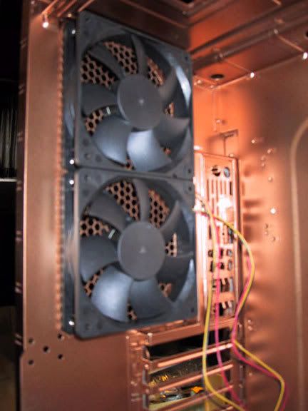
The first thing I needed to do was account for the air flow in the case. There are already places for (x2) 120mm fans, and a larger one up front (whatever might have been there was gone when I had gotten the case). This really made the placement of the fans I wanted to use a no-brainer. Unfortunately, the perf grill of the case was maybe 50% open, so not the best for allowing the case to breath. I decided to cut out the original perf (it was actually part of the stamped steel paneling), and replace it with a much more open hex mesh, that I had used on a previous computer.


Chop03-FrontCloseUp.jpg

Here i have cut out the front of the case to allow for my main intake fan, which is a 140mm AreoCool fan. I would have gone bigger, but the next size up was 200mm, and although it would have fit, I felt that it would have begun to interfere with other internal parts. The remains of the original perf that I removed is laying in front of the PC Case.

Chop01-Back.jpg

Here is the back of the case. In addition to removing the bumped out perf areas, I also had to cut out the old I/O port, since it was also part of the stamped back panel. That was a nervous cut, since I knew I would have to get it as dead-on as possible, so that the ports on the back of the new motherboard would line up with the supplied I/O panel. Again, the wreckage of the industrial jig-saw is seen in front of the case proper.

Chop02-Front.jpg

The circled area is where I would have had interference for the power on and reset switches. The switches I purchased are industrial vandal-proof switches, and will actually stick into the hole in the case a small bit.


Since I am completely redesigning this case, I had to come up with a new front that matched my design. The plastic front that came with the case was not only unacceptable to my design, but it was broken. Honestly, that is quite fine with me, as I would prefer to make a new front to make the case as much my own as possible. So, knowing how I would manufacture the front, I wanted to be able to bolt the front panel on from inside the case. This meant taking some of the metal out of the case around certain mounting points so that I could access the bolt, even if the case still had all of its internals inside.

Chop05-PlateSide.jpg

Here are two locations (circled in red) where I had to remove metal to allow for the hardware (which, btw is a big meaty bolt with two standard washers and a lockwasher.)

Chop04-TopCorner.jpg

Here is another place I needed to modify the case for a bolt. It is the top left corner of the case seen from behind. You can actually see it holding on part of the new front panel onto the case.

...which brings me to the new front of the case! (well at least a small part of it). Your actually not going to get that much from the next few pictures. I will tell you that I have made it out of 2 sheets of 1/2" thick acrylic - yes, solid acrylic. Yes it will weigh a lot. Yes, it machines very nicely.

Face01-BackPlate.jpg

This is the first layer of 1/2" acrylic. The acrylic is actually tapped to allow the bolts to thread right into it. I am using so many washers so that I can use a 3/4" long bolt and have the threads go right up to but not proud of the face of the first sheet of acrylic (1/2" long bolts were just too short, since I am biting into acrylic). As you can see, the DVD Burners have been placed along with the front fan, and the power / reset buttons. Additionally, you can see tons of drilled out holes. Most of them are there to straddle rivets, so that the acrylic piece sits flush to the case.

Face02-FullAcrylic.jpg

Here is the full 1" thick acrylic face, completely aligned, bolted up, tested, and straddling all of the components that interact with the face of the case. I wonder what those two large holes in the case about mid-way up could be for... Hmmmm.... The acrylic looks brown because of the protective paper that is on it from the factory. At this point, the acrylic face is just taped together. In the near future, I'll glue it up.

Now comes the time where I sand, grind, and sand some more, along with scraping off old stickers and adhesive gunk, and getting everything as polished as possible before I painted it. Sorry, no pictures of that part.


Time for the Finishing!
Wow. What an adventure. I wish I had been keeping track of hours spent, but I was more concerned with getting the case up and done... so, eh. At this point, I break out the solvents and wipe down the case to get all metal shavings, grease, grime, dirt, and last bits of sticker residue off the case, and all other parts I'll be painting.

First up, painting the case skeleton, the cut to size hex screens, all of the hardware, the HDD cage, and whatever else I needed for the internals installation.

Obviously, the first step is priming, so here are a bunch of pictures the case being primed...

Prime04-IOPanel.jpg

I installed the I/O panel prior to priming and painting. You can see it in this picture. Yes, I did check to make sure it would line up, and guess what? It does! Yay me, I can use a ruler.

Prime03-MiscParts.jpg

Lots of the misc sundry items in a state of primer.

Prime02-CaseAndMisc.jpg

The front of the case.

Prime01-case.jpg

And now the back and side.

The nice thing about primer, it drys fast (I tend to get impatient about paint). Here comes the paint!

Paint01-Front.jpg

Here is the new and finished front of the case (that noone will ever see). It is rustoleum copper metallic spraypaint. I was surprised, it went on really nicely.

Paint02-Back.jpg

And here is the back...

Paint03-Side.jpg

The inside...

Paint04-CaseAndMisc.jpg

And now all of the misc doo-dads.


.
..
...
So...let me tell you now that I can be impatient, especially when I work on a project that I am stupidly excited about. To me, waiting for paint to dry is about equal to having your fingernails sheered off by bamboo stakes. Somehow, with a forced shower, a forced nap, and forced eating, I managed to get through it to where the paint was cured enough to handle gently (there was no way I could wait 48hrs - sorry just no way in hell it would have happened. Ever. Well, unless you drove me to another state and pushed me out of the car to walk home)
 
Since we are waiting for the paint to dry, I'll show off the guts that will ultimately go into the computer. To preface this, I wanted a multi-processor computer that could handle stupid amounts of RAM so that I could run 3d computer animation programs as quickly as possible. I ultimately decided to build a machine that would use the Vista 64 bit OS. OK, on to the parts!

Guts01-CPU.jpg

This is the heart of the machine. It has 4 processors, each rated at 2.4GHz, stock. The Q6600 is a stable, tried and true processor that has really good over-clocking abilities (which I will be taking advantage of).

Guts04-CPUcooler.jpg

If the heart cannot breathe, it dies. This is my CPU cooler. It is two pounds of copper (an incredible, if not expensive heat conductor) and a 110mm fan. This thing is about the size of a large grapefruit.

Guts02-MoBo.jpg

This is the motherboard. Short of the most horridly ridiculous box art, it is actually a really good motherboard with very nice over-clocking potential. You know, it makes me wonder who designs these and video card boxes, which almost always have really lame artwork on them. I think there is a job possibility there, right up there with the guy that writes fortune cookie fortunes.

Guts06-VideoCard.jpg

Fortunately, the people at EVGA have much better taste in box art than Abit. Instead of screwing up and doing something horrible for the cover, they played it safe and just avoided the entire problem altogether. What can I say about the 8800GTX that has not already been said? It is a great budget video-card, even moreso now that the9800's are out.

Guts05-PSU.jpg

This unassuming black lump is my 610w PC Power power supply. It is energy efficient, has the fan in the back (alot of them now-a-days have them on top, and I needed it on the back for my design).

Guts03-DDR2.jpg

Inside these shiny boxes is RAM. Lots of it. In fact, there is a whopping 8 GIG of RAM in there. This is the best company ever. G.Skill RAM - G.Skill - WHERE SPEED IS! You have to love that.

In addition to that, there are two DVD burners in the machine (just normal w/ lightscribe), and two hard-drives, one 160Gig, the other 500Gig. Sorry guys, no pictures of them (although the DVD burners (samsung) did get some play in earlier pics.


The Assembly!

Here is where I delicately assemble the entire computer, hook it up to a keyboard and monitor, and then cross my fingers...

I started off by installing the newly painted hex mesh and the fans, so that I would not need to manipulate them around other components. I had pre-located the mesh prior to painting and had cut out small sections whenever it fell over a screw location. All of the fans went on perfectly smoothly.

Assy03-FrontFan.jpg

Here is the new front fan (140mm AreoCool) and hex mesh. I've removed the stickers on the front of my fan, since it didnt really go with the clean look I wanted.

Assy04-RearFanGrill.jpg

And of course, we have the rear fans. Since the fans are black, it is very hard to see them. BTW, those fans are 120mm scythe fans, which i hear are really good. They should last forever, move alot of air, and are quiet. What more could you want?

Assy05-RearFansProper.jpg

Here is a picture of the rear fans from inside. If you look closely at the edge of the fans, you can see where the hex mesh is sandwiched in between the case and the fan. The mesh does not interfere with the fan at all. I did spend some time clipping the mesh so that it was only completed Hexagons in the pattern. Any little points or partial hexagons were removed so that I would not tear my fingers off later on their sharp little edges. Plus, it looks a lot cleaner that way.

Assy07-Feet.jpg

The next step was installing the new feet onto the case. Right now the acrylic feet are not painted, but that will be resolved in the near future. While I was in this step, I also installed the risers for the motherboard inside the case. Unfortunately (or fortunately, as it would be relatively boring) I do not have a picture of this step.


Now comes the time where I install the processor and heatsink onto the motherboard. I didn't take any pictures of the processor itself, since you never know when a bolt of lightning will shoot from your camera and fry your helpless processor.

Assy01-HeatSinkComparison.jpg

Here is a comparison of the stock steel and aluminum processor heatsink versus my huge copper one. Not only is my new one bigger for more heat distribution, but it is also about 1000x more heat conductive. Thermal paste is Arctic Silver 5.

Assy02-MoboAssembled.jpg

Here is that heat sink installed onto the motherboard. You can just now start to see how HUGE that heatsink is.

Assy08-PSUOctopus.jpg

In goes the Motherboard, the video card (also HUGE), and the power supply. You can see the hungry octopus of PSU wires creeping over the case side.

Assy09-RunningWires.jpg

Ahh, thats a little more manageable. At this point, all of the components are hooked up to each other. I only have one stick of RAM in at this point, just to boot the machine and make sure everything runs. NOTE: although I don't have that many wires, I still want to do something in regards to wire management. I just came up with an idea this morning, so I'll look into it, and see about adding it to my next case mod steps.

Assy10-InsideCase.jpg

Another view of the inside of the case, with a little more close-up of everything. You cannot miss how big that video card is.


The Moment of Truth


Time to cross your fingers, hook up the monitor, plug in a keyboard and mouse, and hope things are not too stupidly wrong or broken....

We hit the power button (currently, the only one I have access to is on the Motherboard)...

...

and...

...

ItLives01-PostPOST.jpg

SUCCESS!!! WE GOT THROUGH POST!

In all honesty, getting through POST was all the computer managed to do on Sunday night. No matter what I did, I could not get the computer to boot off an OS disc to do the OS install. I kept getting "NTLDR missing" errors. I spent hours monkeying with the hardware, swapping RAM sticks, trying different configurations, even pulling an old IDE HDD with XP and trying to boot from that. Nothing worked. I spent about 6 hours working on it with the help of another Tom (Tom M - thanks!), until at about 1:30am. After that, I just went to bed defeated.

The entire next day at work, I was milling over everything that I had tried, and by the end of the day, I had several plans to try, and multiple contingencies lined up. I had a bet that it would be memory, motherboard and then processor in that order from highest to lowest on likely problems. ObviouslyTom was set up to drive his rig to my house that night with his computer (he also has a 6600, and different RAM) and we would have test all of those components to see if I had received something DoA from the 'Egg.

Fortunately, my most promising hypothesis was correct, and within 5 minutes of getting home last night, I had the computer booting up from the Vista disc.

The problem? The RAM. It is rated at 1.8-1.9 volts, optimally. The Motherboard auto-detected the ram and set the voltage at 1.8, the bottom end of its functioning range. I upped it to 1.9, and everything blasted right up - the RAM was just not getting enough voltage to retain information!. Once I was up and running and updated, I ran Prime95 for a few hours last night, and it seems stable. Current core temps are 21-22°C idle and 39-40°C under full load. I didn't lap the processor, and the case is still just a frame w/o sides, so the airflow is not as direct as I would like it, plus the thermal compound had just been set, so hopefully with a little more time, those numbers will come down some.

ItLives02-Itunes.jpg

Here we are, vista64 up and running, updated, and I am just reclining back listening to some music. (Next on the shopping list, a 24" LCD to get rid of that tank of a CRT)

Well, thats the first half of this journey. I have a running computer, and a fairly badass computer at that. Next will come at least two more updates, one will be for overclocking the processor, I'd like to hit 3.6GHz on it,but we'll see how it goes. The other post will be to finish the case, and show you the TRUE vision that I see for this PC. Fortunately, I was smart enough to make my design work around the now functioning computer, and I shouldn't have to pull any of the working bits out to complete it at this point.

With that said, I don't think you'll be disappointed. It will take a lot of work, though, so be patient!

Skully.
 
if you want to overclock your processor that much you might want to consider water cooling it. Also, very nice build so far. can't wait to see more updates
 
Thanks for the comments. This is just basically the armature of what I think will be an incredible case. There are literally hundreds of parts left to go into the case exterior.

I thought about water cooling it, Heck, the case is big enough. I could almost get an aquarium in there. But... at the end of the day, I'm too lazy to upkeep the water cooling. 3.6GHz would be the absolute top end that I would ever care or want to go. If I get there, rock on, if not, no problems either. In some ways, it is more of a curiousity thing just to see how far I could push it reliably.

See, short of my mac, my other PC is a totally frankenstein'ed 423 pin lol-Dell Dimension 8100 (sorta). I managed to get the processor up to 2.8GHz. The FSB on it is 100Mhz. Unfortunately, it doesn't matter how fast your kid is if he still takes the short bus to school...

So coming from that, this thing is astounding. Hope for the best and plan for the worst ^^.
 
thats awesome how u took an oldschool case and are updating it. i like! keep us updated.
 
this makes me wish i never threw out my inwin q500 full tower. anyone remember that bitch?
 
This is looking good so far. I love the color. Please don't place your brand new computer parts on a towel. You can end up killing them.
 
I think i know what s-d stands for but i dont think ill say as its rather dirty;)
 
I'm not personally a fan of the copper, but damn man, that's a slick paint job + acrylic setup you got going there!
 
I have been talking with Skullkyng about this project ever since I gave him the case (which is an old Gateway ALR 7200) and I am curious to see what the final outcome will look like.
 
You think thats huge.

I used to have the ALR8200.

Add another 5 inches of height, and another 6 of depth. O_O'

I traded it with a guy before I moved for a Chieftec Dragon case for my PC, as I wasnt taking that huge bastard with me.

(This was like 3-4 years ago)
 
A few things of note for today:

Yeah, I was not thinking when I put the towel down. I had done that for the paint. At the end of the day, everything worked, so thats the important part (that and it won't happen again).

BIG NEWS: I can now complete about 80% of the outside of the case!!!! All of the parts and pieces I've been machining from acrylic are now done. I'll post some pics tonight of my stash. Additionally, expect to see a couple of updates between now and the weekend.

Now I just need to make a huge order of materials from McMasterCarr.

Oh, here is a question. I need to wire my buttons to the motherboard. Can anyone post a link to the right kind of connector to hook to the pins on the MoBo?

Lots of work and sanding to do tonight.

More pics to come, either late tonight or tomorrow morning.
 
Are you sure those rear fans are 80mm? They sure do look like 120mm to me.

Your right, they certainly are120mm. I was really tired when I wrote this one up.

Life happened last night, so I won't get to do any updates until this evening. Sorry guys!
 
OK< finally an update.

This is the work that I completed yesterday after work. Yesterday I began the very long task of doing the prep-work for the finishing of the parts for the outside of my case. Most of it is machined acrylic. Unfortunately, on some of the thicker pieces (parts go from 1/8" thick up to 1" thick), the router left chatter marks on the sides. (BTW BIG MONDO PROPS to J.M. for doing the routing). So i had to sand the edges. I'm also using an orbital sander to scuff up the face and back so that the primer will stick better to the machined pieces. Additionally, my box of hardware arrived to mount the acrylic panels to the case. This is great because that means that when I am done with cleaning up the acrylic, I can do a dry-run on the case panels, and drill any holes that I may need. I'm really hopeful to get far on the case this weekend.

OK Now for pictures!

Since it is such a nice weekend, I will get to play outside. Here you can see me getting all of my stuff set up.

Day01Finishing-11.jpg

IN this box is my orbital sander. The tape will be used to hold the panels together when I get to the dry-run.

Day01Finishing-13.jpg

Drill and tap set. There will be several pieces of acrylic that I will need to add threads to, since the hardware cannot protrude of the back of certain panels, or in certain places.

Day01Finishing-09.jpg

This is probably the best acrylic adhesive in the world. It dries super fast and it drys super strong. You apply it with the syringe. (just make sure it works with the acrylic you are using. I am using a G-grade acrylic, NOT lexan.

Day01Finishing-10.jpg

It is Friday, and I'm chilling outside working on my new computer case. How can you not have something like this.

Day01Finishing-14.jpg

This is the box of hardware that will be used with the case. It is mostly pretty standard stuff. Washers, nuts, threaded rods, that sort of stuff. You'll see the exact stuff later this weekend, when I start opening up the boxes and bags.

Day01Finishing-12.jpg

This is MOST of the stack of acrylic I need to finish. As you can imagine, it is going to take me quite a few hours.

Getting to work!

Ok, so as you may recall, the face of my case was made of two pieces of 1/2" acrylic. The first thing I did yesterday was to sand the joining surfaces of the two pieces of acrylic. This does a few things, it gets rid of any dirt, and it allows the adhesive to capillary better.

Day01Finishing-08.jpg

Here are the two face pieces. I was laying them out to make sure I glued them up properly. Once that glue bonds the acrylic, that is pretty much it.

Day01Finishing-07.jpg

Once I was certain I had the alignment dead-on, I very carefully taped up the corners and some of the exposed sides to hold the pieces in perfect alignment. (this picture is actually of me removing the tape later, but you get the drift). Once you get the acrylic taped together, you fill your syringe with the adhesive (it is colorless, and looks like 'thinner" water - not as viscuss) with a turkey baster. I then ran the tip of the syringe (starting with the holes in the middle of the panel) around any seams where the two panels touched. The adhesive is so thin that the seam actually draws (via capillary action) the adhesive in, so you really do get decent coverage. You can also use thin strips of say piano wire to make a gap between the panels load up the adhesive, and then lower it down, but I feel that is too risky (at least for me). Once I did the insides, I then went around the edges, where there was not tape, then I started to remove the tape and finish the rest of the outside edging. The adhesive sets up very quickly, and is a very strong bond (kinda like superglue).

Once I was done gluing up the face, I set it off to dry (not that it was necessary) while I worked on some other parts. I chose to do my finishing by acrylic thickness this way I could eliminate a group, and ensure that all of the like pieces recieved the same style of finishing (for example, the 1/8" acrylic will not need the edges sanded, but the 1/2" stuff certainly will).

Day01Finishing-06.jpg

Here is a picture of a typical 1/2" piece of acrylic. I've just finished sanding the edges (with sandpaper, by hand), and then the face and back with orbital sanding. You can see the bag of acrylic parts in the back. I have a long way to go.

Day01Finishing-03.jpg

Two hours later, here are all of the 1/2" pieces, now finished! I used my orbital sander case to hold them as I finished them.

Now back to the face. At this point, the glue is more than set up. I use the orbital sanded to sand the four sides to make sure that the edge is perfect, then I sand both the face and the back of my now 1" acrylic face.

Day01Finishing-05.jpg

Here is the glued up piece. By this point, the edges are so smooth, that although you can see the light shift in the edges, it is completely smooth. Once done the edges and face, I had to hand-sand the inside of the large hole, which is ultimately where my 140mm fan sucks in air.

Thats it for now. After I finished the face, I called it a night, did clean-up, and then jammed on Rockband with some friends. As soon as I post this, I'll be going back outside to continue with sanding, and hopefully, the next update will be more exciting - maybe you'll start to get to see the design!
 
OK, well I just got done putting in a stupidly long day I started at about 9:30 this morning, and short of the break I took when ObviouslyTom stopped by this afternoon, I worked straight through until now (just shy of midnight). . You'll get to see the fruits of my labor below.

The first thing on my list of chores was to finish sanding up all of the acrylic parts that I still had left to do. I would say I only completed about 25-30% of all of it on Friday night.

Day02-11.jpg

Here you can see the piles of acrylic that still need to be sanded. The pile on the right is the 1/4" thick material. The pile on the left is the 1/8" material. I chose to go with the 1/4" material first.

Day02-10.jpg

The 1/4" material is done!! Excellent. I'm maybe 60% done with the sanding of acrylic now.

Day02-09.jpg

The intimidating pile of 1/8" acrylic. I've been putting this off as long as possible because these pieces actually needed the most clean-up, and since they are only 1/8" thick, are more prone to accidental damage or snapping during rough sanding. Not the best combination.

Day02-08.jpg

Here is a typical piece. You can see there is leftover material on the edges, and the holes are not completely drilled out. This is a pretty extreme example, but gives you an idea of some of what I was working to clean up.

Day02-07.jpg

Here is the same piece, all cleaned up, but prior to sanding the face and back. I did all of the edges first, then did the orbital sanding afterward, just to keep down the juggling of tools and parts.

Day02-06.jpg

As you can see, all of the acrylic is now finished! I didn't even manage to bust any of the 1/8" acrylic, much to my relief. There were some really frail pieces that were really flexing while I was sanding them. As you can also see, it is getting quite dark outside at this point as well.

I thought about calling it a day here, but then, I didn't stop working. So, now you get to see this!

.
..
...

More stuff on the computer face!

If you remember from yesterday, I glued the two face panels together. Well, I ddecided to do a dry-run on the parts that are installed onto the face.

Day02-05.jpg

Here is the face with all of the secondary parts taped on. Everything fit just how it was supposed to, which is great news for me! Time to really start putting this together now for a test fit.

Day02-04.jpg

Here I am drilling and tapping holes for acorn nuts. The acorn nuts are on threaded rods that are then threaded into the newly tapped acrylic. The rods and acorn nuts will do the work of holding this thing together after I get done painting all the parts (which ultimately means that whatever I put together for the dry run, I'll have to take apart to paint, then completely reassemble again).

Well, here it is:

Day02-03.jpg

This is the face plate with about all of the acorn nuts I can safely tap. Most of the remaining acorn nuts will be glued down. I'll cut the rods down so that they fit into the holes of the acrylic of the secondary pieces, which will be held tight by glue.

Day02-02.jpg

Here is just another shot of the face panel.

Day02-01.jpg

And one more for good luck. Ultimately, when assembling this, I did find a small measuring error on my behalf that will require me to recut about a dozen pieces. I thought I had taken everything into account on my detail drawings, but it just goes to prove that you cannot catch everything on a detail drawing. Ultimately, not even a big deal or a set-back, just something to learn from in the future.

OK, thats it for tonight. Lots more work to do tomorrow. Catch everyone on the flip side.
 
WOW.... Thats absolutely amazing. Keep up the work man, I have high hopes for the outcome of this project.
 
OK, not too exciting of an update today. Between the rain, and it just being Sunday, I decided to take it easy.

Today I began to work on the side and top panel of the case.

Day03-07.jpg

Here are the side-panels of the case. Gateway in true lazy form used the same panel for both sides, they just flipped one up-side down. This makes the perferated section a littme more "fun" to deal with later.

Day03-08.jpg

As you can see above, the first thing I did was did a test it of all of the pieces for the side panel. Everything seems to fit just right. I've realized though, that I cannot really bolt the pieces on (or at least not nearly as many as I had thought, as the actual frame of the case interferes with them. This is mostly due to the bolts being right up to the edges of the panels. I'll have to take a reallllly good look at this, but I think alot of my acorn nuts may be glued in place, rather than initially screwed, like I had planned.

Day03-09.jpg

This piece will ultimately go where those ridges on the back of the case are. They will be cut out before long.

Day03-07.jpg

Once I had the edges of the panel laid out, I could see exactly where I needed to put the windows that would go into the case. I only laid out one panel, since the pattern of acrylic is identical on both sides. I just simply measured from the first panel and placed the circles onto the second panel.

Day03-06.jpg

Here is a better picture of the circles. The blue marker identifies where I will cut parts out with my jigsaw. Let me explain the 3 circles in each cluster. The outside and middle circle are the perimeter of the trim ring ( you can see a mounted trim ring on the face of the computer in my last post). There is a window that will sit within the trim ring. The smallest circle is the inside of the ring that will hold the window between the case and itself. I wanted to minimalize the amount of lip you would see below the window, while still giving it ample structure to be supported (so it does not fall into the case). The large how drilled into each pattern is the starting hole for the jig-saw.

Day03-05.jpg

Since I was drilling, I back-stepped a bit and drilled the actual holes to mount the trim ring to the panel. I did this by taping the trim rings to the panels, then just using the holes already in the acrylic trim-rings as a guide. It worked well. I figured it would be smarter to pre-drill now, than to try and do it later after I turned the pieces into swiss cheese.

Day03-04.jpg

Here is the top panel. It is basically following the same work flow as the sides. The holes for the mounting ring have already been drilled. The opening will ultimately be in the front of the case. The overhanging acrylic parts are at the rear of the case.

Day03-03.jpg

And here is a side panel, drilled, cut with a jig-saw, cleaned up with the ever popular dremel, sanded, orbitally sanded, and called done.

Day03-02.jpg

And here is a picture of an equally complete top panel.

Day03-01.jpg

Finally, two completed side panels, side by side. That takes care of the major holes in the case panels.

I think my next step will be to look at the locations of the exterior parts and figure out how best to attach them. I generally prefer mechanical fasteners over adhesives though. I've been thinking of a combination of the following attachment methods, epoxy, the acorn nut assembly (acorn nut, threaded rod, washer and nut), and then driling a hole in from behind, counter-sinking it, and then using flathead fasteners to go into the acrylic (which I will have to drill and tap).

So, thats all it is going to be for today. Enjoy the rest of your weekend all.

Also, thank you everyone for all of your great comments!
 
You can use some knid of bondo or something to fill those old perforated sections in.
 
Monday Update!

Well, I just spent the last 5 hours on the faceplate to the computer. There were quite a few parts that are to go onto the side of the acrylic face. The problem with cast acrylic is that the thickness falls in a range. Just because it is called out as 1/2' thick does not necessarily mean that is what it will be. This was the case with me. I had in some places (x3) pieces of 1/2" acrylic, which should have measured out to 1-1/2" total in thickness. In reality, due to the variances in thickness, instead of 1-1/2" thick, it was actually closer to 1-3/8" (maybe even a tiny bit thinner than that even).

So... that means that every single piece that has to go onto the side of the face plate needs to be cleanly shaved down to match the thickness of the face plate. It took a while to do it cleanly. In the end, it took a combination of a miter saw, Dremel tools, orbital sanding, hand sanding, and some files to get everything "just right".

Day04-05.jpg

Here you can see one of the side pieces. The red mark is actually my cut-to line. When I see no more red, i know I'm getting close.

Day04-09.jpg

Here is my miter saw. Since I am exceptionally fond of my fingers, and most of these pieces are really tiny (at least when you want to cut something on a miter saw), I used an old reject piece as an extension. A little bit of green tape, and your good to go. Oh, make sure you cut acrylic VERY slowly when using a miter saw, or else you'll just end up breaking the acrylic, or making a dangerous projectile.

Day04-07.jpg

Here you can see several cut to fit pieces applied to the side of the face. One side down, a whole lot more to go.

Day04-06.jpg

Here is a better view of the first layer of acrylic that goes onto that side. Yes.. There is more than one layer. Also, that piece in the middle of the face was just taped there so I wouldn't lose it. I missed it until the end of my last clean-up, and instead of hunting for the bag it went in, I just did that instead.

Day04-04.jpg

Here, the first layer of acrylic is applied all around. Almost done with the faceplate!

.
..
...

OK, so here it is. The faceplate with all parts dry-fit.

Day04-02.jpg

You can see the second layer of acrylic applied to the sides now. It is certainly a substantial faceplate.

Day04-01.jpg

Here is another view to show off more of the depth of the faceplate. Man, this thing is cool looking.

So, at this point the faceplate is more or less ready for tear-down and finishing. I still need to go through and retrofit some of the pieces that go onto the top case panel as well. Fortunately, the sides are pretty straight-forward. There is just a lot of interacting detail between the face and top that I need to make sure is as clean and aligned as possible.

I found an adhesive that is really good at bonding acrylic to metal, in fact it has a 3000 lb shear-strength. I'll use that in conjunction with flathead machine screws to secure the panels to the side of the case. They should arrive on Wednesday I believe.

Speaking of Wednesday, that is when I'll be able to do my next update. Life calls tomorrow, so I don't get to play on my computer case.

Night all.
 
Thanks for all of the support and encouragement, Runedrune (and everyone else)! I really do appreciate it.
 
Hello all, sorry for the delay in updates. I made some decent progress tonight (though never as much as I hope to). Lets get started.

Tonight, my focus was on the top panel of the case. I basically had to do the exact same thing to the top that I had done to the face, which was shave down assorted acrylic parts 1/16-3/16 of an inch to it flush, due to variances in the the thickness of the acrylic due to the casting process by which it is made. Since pictures of me sanding cannot be that exciting, I've skipped to the end, where I had finished the shaving of parts, and had the entire thing put together.

Day05-16.jpg

Here is a view of the top panel. The hole in the panel will actually be at the front of the case.

Day05-15.jpg

Here's a close-up of the corner. Again, this is the front of the panel.

The next three pictures show the depth of the acrylic fairly well:

Day05-14.jpg

Picture from the top down.

Day05-13.jpg

Picture from the front.

Day05-12.jpg

Nice isometric view.

At this point comes the moment of truth - to make sure it sits right on the case, and aligns well with the front panel. The seam between the front and top panels is the most complex, and crucial seam to get right. Lets see how I did...

Day05-11.jpg

Good to see the top still fits. The top has to be the first panel I put on, when I do the final assembly.

Day05-10.jpg

Here are all of the panels on the case. Of course the side panels are nowhere near complete - in fact they are barely started - but the seams all look really good. I should be "mostly" in the clear from this point on. Just a few last minute things to work out. (Note - the front is actually screwed on from the inside of the case)

Day05-07.jpg

Here is a closer picture of the panels installed on the case.

Day05-08.jpg

Here is that tricky top joint. I waited to tape up the final parts until I had an opportunity to test everything around the case structure. Now I know exactly what I need to do to the parts I have to finish this section off (more sanding).

Day05-09.jpg

Here is a front view of the case. You can see the start (top) and reset (below) buttons are test fit into the acrylic face. I finally wired them up. I was having a really hard time finding a 2-pin connector for them, so I ultimately ordered (x2) LEDs with 18" wires and a 2 pin connector, and just cut off the LED part. The LED wires were long enough so I just threaded them into my buttons. All in all those two sacrificial LED's cost me 33 cents.

Day05-06.jpg

Here is a closer look at those buttons, unfortunately the pictures were not coming out clearly. They work great, and will outlast the case, which will outlast most of the human population, the way this thing is being built.

One of the things I had to fix that I did not catch eariler was that I was unable to thread the top left bolt that held on the acrylic face. The top panel had a flange that was in the way of my (very small) opening space.

Day05-05.jpg

Here you can see the notch I've cut off the top panel to allow access to the mounting hole for the face.

Day05-04.jpg

And after a little more modification, and some filing and sanding, this is how it ultimately ended up. It will still be a small, frustrating hole to work a bolt in, but it is "do-able", since I checked.

Now that I had all of the bugs worked out from the face to top joint, I went back to work on the top panel to secure as many acrylic parts as possible with hard fasteners. The 1/2" acrylic was drilled and tapped and threaded into from below the top panel, locking it into place. (I used a threaded rod, washer, and nut) - NOTE TO SELF - GET LOCKTITE. Additionally, I secured the 1/4" acrylic with acorn nuts.

Day05-03.jpg

Here are all of the holes for the acorn nuts for the 1/4" acrylic parts. It is an assembly of acorn nut, threaded rod, washer and nut that will secure the acrylic to the metal top panel.

Day05-02.jpg

And here is a picture of the bottom of the top panel, with all of the hardware installed holding all of the acrylic, minus the 1/8" acrylic, which will be secured by adhesive. Ultimately, the three hardware assemblies holding the small 1/4" piece at the front of the case had to come out, as they interfered with the fitting. I'll just have to glue those guys in place.

Day05-01.jpg

Here is out final image, it is the hardware laden top panel now on top of the case, just to check of clearance issues (which there was). As you can see the three acorn nuts in the front center have been removed as they were hitting the structure below. I could have hacked up the structure to make them fit, but just setting the acorn nuts with adhesive seemed like the safer plan to me.

OK, thats it for today. I still have quite a few things to do on this machine, some which you may guess, some of which, you'll have no idea until I actually show them to you. I'm hoping to be pretty productive tomorrow, and over the weekend, and if I'm lucky, I'll be getting a coat of paint on the front, top and sides.

Tomorrow, we'll start the hard work of final placement and hole drilling for the side panels. Have a good night everyone.
 
OK time for a big update. This is everything I accomplished Friday, Saturday, and what is done so far today. Enjoy.

FRIDAY

The first thing I did on Friday was to tape up the side panels and add them to the taped up front and top panels to make sure that everything lined up and fit the way it was supposed to.

/crosses fingers/

Day06-24.jpg

Here is one of the two side panels taped up. Since both of the side panels are identical (minus the grill location), there's no sence in posting pics of both.

Day06-23.jpg

Right away i notice a problem. The ridged finger grips that were part of the side panel that I cut away ended up being larger than the acrylic piece that was to cover the hole in the metal panel. It is not bad, about 1/16" each in those two corners, but still, this will need to be fixed.

Well, despite that oversight, lets look at the computer, now with all panels on it.

Day06-21.jpg

Here you can see a good view of the entire computer from the left side. My biggest concern was that the compound corner might be out of alignment.

Day06-20.jpg

Here's a close-up of the corner that I was concerned about. It is off just a hair, but when I raise up the front panel (it was not securely fastened, and has some play), it was basically dead-on.

Day06-19.jpg

Here is a picture of the other (right) side of the computer.

Day06-18.jpg

And here is the view through the window(s) in the left side of the case.

Now that I was happy that the panels worked like I needed them to on the case, lets re-address those small openings on the corners of the cut-out that should have been covered up by the acrylic panel. How to patch a hole in metal...

Day06-22.jpg

The easiest solution? JB-Weld! This stuff is amazing, and loves to stick to metal. It is hard when it cures, can be sanded, filed, ground, all kinds of good stuff. I once used this to fix my hood latch when I had my 300zxTT.

Day06-17.jpg

Here is the JB-Weld applied to the side panel. I made a flat surface under the opening with three layers of tape pulled tight. Then I just glopped on the JB-Weld with a handy popcicle stick. Just let it dry for the next 16 hours, and you are good to go.

Thats it for Friday night.

SATURDAY

Saturday was the day of committing to what I've done, and permanently secure stuff together prior to painting. This was basically the point of no return. Hopefully all of this tedium will have paid off when I go to the final assembly. I jumped all over on the items I worked on during Saturday, but I'll stage them in like groups just so it is less confusing.

The first thing I did was to go back and work on the face panel some more.

Face Panel

Day06-16.jpg

Here is the face panel. The build-off parts that are on the front have now been secured via that #4 acrylic glue I had posted a few days ago.

Day06-13.jpg

Here it is now with the side build-outs glued on. Although the glue sets up in a few minutes, I was generally letting the panel sit for 30 minutes to an hr before handling.

Day06-10.jpg

Now that the front panel is one giant block of acrylic, I filled the edges and corners with bondo so that any seams that might have been visible after painting go away.

Day06-07.jpg

And here it is, glued up, bondo'ed, sanded and ready for the final wipe-down and paint.


Edge Parts

Day06-09.jpg

I basically had to glue up a bunch of other parts that would ultimately wrap around a corner. Here is the start of them glued up.

Day06-08.jpg

Here you see all of the corner wrapping panels, now slathered in bondo. Again, I wanted to make all of the seams that I could, go away.

Day06-06.jpg

And finally, here they all are after sanding. These parts are now ready for final clean-up and paint as well.

Side Panels

Time to revisit our side panels that we fixed up last night after JB-Weld.

Day06-12.jpg

This is what they look like after sanding. It worked perfectly. I was a bit worried about the "weld" popping off since the metal was thin, but it held like a champ.

Day06-11.jpg

Here is the entire side panel sanded down afterwards. I wanted to strip off all of the old paint to make sure what I applied stuck like mad. There is still another step on the side panels before they can go into paint.

Day06-14.jpg

Additionally, I sanded down the top panel as well. This guy is now ready for paint.

SUNDAY

And here we are, to finish up all of the last details that I can think of before we paint this stuff up. The first thing on the agenda - finishing up the side panels. They still had one more step before they were completed.

Day06-04.jpg

This is super-ultimate-omega-IndustrialGrade-Superglue. It is capable of gluing metal, glass, plastics, any manner of things, just like regular superglue. But unlike superglue, this stuff has a 3000 pound sheer strength. A rhino could do chin-ups on whatever is glued together with this stuff all day long. It has a 10 second set time though (although it seemed to set in about 3 seconds when I was using it). So.. when you use it, don't screw up, if you do, act REALLY fast, and pull REALLY hard... Not that I figured that out the hard way... :rolleyes: Oh, if you want it, it is 17 bucks a bottle. I got it at McMasterCarr - and industrial supplies company.

Day06-03.jpg

So anyway, I used that superglue to fasten these parts to the side panel. I taped off exactly where each piece was to go, then applied the glue to the panel. I then lined up the acrylic piece over the glue, and then placed it down. Once down you have a second, maybe two to slide it if you need to. After that, it is pretty much done. Literally 20 seconds after applying the first piece, I was picking the entire thing up by the acrylic. It did not budge. Good stuff, that.

Fastening Hardware.

As you may have figured out, There is going to be copious amounts of hardware on this case. This is prep-work to handle the finishing of all of that hardware.

Day06-02.jpg

Each one of these holes will hold an acorn nut with a threaded rod on the back. If I counted correctly, there are 309 acorn nuts of assorted sizes. That is a lot of metal, and probably weighs about... 8-10 lbs. I'll throw it all on the scale later.

Day06-01.jpg

This is a close-up of the other side of the hardware paint sticks. As you can see, there are also tons of washers and nuts.

Day06-25.jpg

One thing I had to do was cut down a bunch of the threaded rods. I was originally planning on attaching everything by either tapping the acrylic, or by locking it down on the far side with a washer and nut. In most cases, it just didn't work out that way. BTW, all of the threaded rods are installed into thier acorn nuts with lock-tite.

Day06-05.jpg

And just in case you doubt my count, here is a typical side-panel. Go ahead and count for yourself. Also, enjoy the view of the to-scale layout I used to help me track all of the parts and pieces that are a part of this case.

Unfortunately, I was all geared up to paint today as well, but it is overcast, threatening of rain, and the humidity is right on the recommended allowances of the paint I'll be using. I'm not going to screw it up after all of this work, so... hopefully tomorrow is a nicer day!

Enjoy the rest of your Sunday.
 
So beautiful...should have sent...a poet.

Keep it coming, I can't wait to see what this thing looks like painted
 
no guesses on what "S-D" stand for, but the look so far reminds me of Twenty Thousand Leagues Under the Sea. if you end up painting it yellow, i'll buy you a miniature Captain Nemo.
 
Alright, back with a big update. Sorry about the delay on this one, but what I was trying to accomplish was just not happening smoothly. At any rate, this is what I've been up to...

Finishing time!

So, everything that can be glued up is glued up. All of my prep work that can be donw is done, time to set up an assembly line and work on the primer and the finishing paint.

Day07-17.jpg

As you recall from the last post, I had drilled out a bunch of sticks with assorted holes. This is why. Every stick represents the hardware on one part of my case (top, bottom, or a side). Here you can see the hardware placed onto the sticks, and awaiting primer and paint.

Day07-16.jpg

Since the side panels are a combination of plastic and metal, I needed to prime each material seperately, to ensure the best adhesion I could. Here is the metal taped off (face and back), to allow me to do the plastic first.

Day07-15.jpg

Here is a primer shot of the plastic primer on the side panel we just taped off. Next to it is the face panel, now also primed.

Day07-13.jpg

Here is a groups shot of a bunch of the misc. parts and pieces. Like the hardware, the sicks represent a particular placement on the case. Additionally, they are broken down a little further, as there is more than one color that will be used on the exterior.

Day07-11.jpg

Here is more or less that same group a small time later, now painted that copper color that the case frame was done in. After I primed, and let the primer dry (I primed on Wednesday and painted on Thursday), I sanded all of the parts down with a fine-grit (400 grit) sandpaper, just to get any rough spots off.

Day07-10.jpg

Unfortunately, I had catastrophic paint failure. As you can see above, there is a textured, almost crazed finish to the copper paint. This happened on a LOT of the parts I had painted. My best hypothosis is that after sanding, I either didn't wipe them down well enough, or that it was just too humid, and the pollen to heavy to actually have painted them outside. This was a HUGE step backwards because now...

Day07-09.jpg

I have to sand down each and every single part and make them smooth again. I just sanded everything smooth, I did not take it back down to base material, so at least I saved myself from having to re-prime everything. Only 3 pieces out of the entire case had to get additional primer applied.

Since I was not going to take any more chances with painting outside, in case the environmental conditions were screwing it up, I set up a room in the house (yes, it is stupid, and it sucked to be in it, but it worked to my satisfaction). I picked my room on Friday, and set up a big air filter, set it on max and let it run in the enclosed room to try and get as much of the dirt out of the air as possible. I then threw cardboard on the floor (it was a concrete floor anyway), and set up my high-tech painting stands (cardboard boxes), and then locked myself in there a stick of parts at a time and finished painting everything (much to my lungs dismay). Once a part was painted and dry to the touch, I staged them in the living room.

So... here you go, pictures of all of the painted case parts, just waiting for assembly.

Day07-08.jpg

Here are the now painted side panels and the top panel. They are painted brass, which is really rather reflective, which is why it is kind of mottled looking. As the metal bends and shifts a little, so does the light reflection.

Day07-07.jpg

Here are an assortment of small painted brass parts, along with the face to the case.

Day07-06.jpg

And here is the first half of the copper parts.

Day07-05.jpg

And now the second half of the copper parts.

Day07-03.jpg

Finally, we have all of the acorn nuts, bolts, washers and regular nuts, all painted brass as well.

Day07-02.jpg

Finally, just one more shot, from back in the hallway of the livingroom, trying to show the entire scope of parts that comprise just the outside of this case.

Including hardware, I say there are close to 500 parts that will need to be assembled, attached, tightened, and glued, before these case panels are ready to be put onto the case. Whew. Thats a lot of work yet. I'm very close though! At this point, everything will not be touched until I get home from work tomorrow, just to give the paint a full 48 hours to cure as much as possible before handling. No sense in rushing it now, and then having to sand everything down again.. eek.

So, with that said, have a great Sunday, everyone!
 
Back
Top