• Some users have recently had their accounts hijacked. It seems that the now defunct EVGA forums might have compromised your password there and seems many are using the same PW here. We would suggest you UPDATE YOUR PASSWORD and TURN ON 2FA for your account here to further secure it. None of the compromised accounts had 2FA turned on.
    Once you have enabled 2FA, your account will be updated soon to show a badge, letting other members know that you use 2FA to protect your account. This should be beneficial for everyone that uses FSFT.

Project: Revitalization

Joined
Oct 2, 2003
Messages
2,173
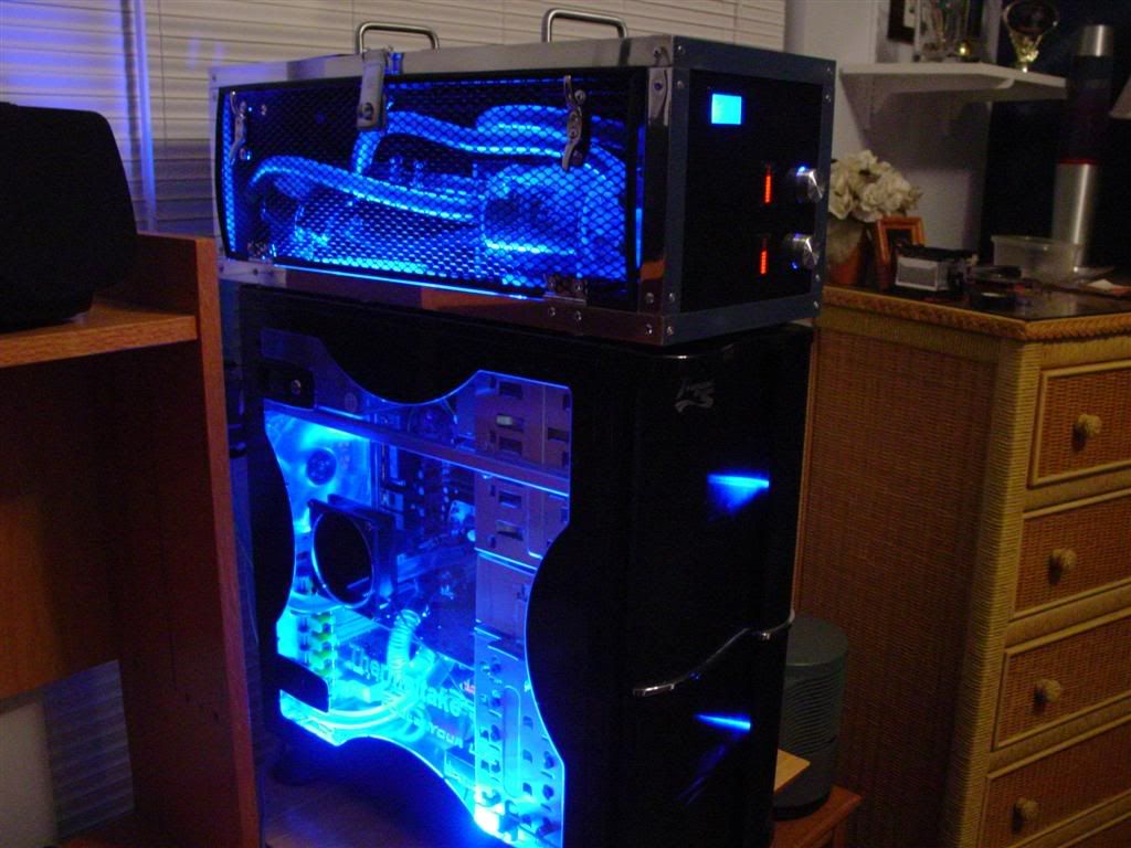
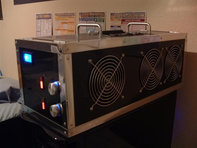
About a year ago, I completed a custom external watercooling enclosure. Here is a link to the original worklog: http://www.hardforum.com/showthread.php?t=915156&highlight=external+w/c+box I was very satisfied with my work. After it has sat on top of my case and been through several moves and LAN parties, however, it has gathered dust, a few marks here and there, and doesn't glimmer as it used to. In addition, the my processor is not running as cool as it used to, and the system was never as quiet as I originally intended it to be.

I am starting this project to revitalize my overall system, but especially the external enclosure. I want to make a few changes so it looks a bit more appealing as well.

Here is the system at near completion, about a year ago:
DSC02371.jpg


Here is the system in its current, shall I say, dilapidated state:
DSCF0065.jpg

DSCF0058-1.jpg


With the flash off (this is more of what it really looks like) there is still some mirror-like shine to the black paint and aluminum frame, but it is not what it once was:
DSCF0059-1.jpg


One of the main reasons why I seek to refinish this system is the leaking res:
DSCF0064.jpg


The dust is pretty bad too :eek:
DSCF0063-1.jpg


Not to worry, though, I have a new criticool reservoir here for a replacement. I could only find the 6" version, though. Some reorganization will be needed so it can fit.
DSCF0082.jpg


Note that I painted the ugly brass colored barbs black. I laid down several prime coats and a nice thick color coat, so hopefully the paint will not flake. They look much better, don't you think? :D
DSCF0056.jpg


To help silence this system, I will be switching out my current undervolted Panaflo U1A's for Sanyo Denki San Ace fans. I'll also switch out my current case fans for these yate loons.
DSCF0060-1.jpg


I also want to change the mesh and handle assembly. I was never a huge fan of the current mesh, but it was cheap. I decided to bite the bullet and buy an AC Ryan
MeshxPanel. I like it a lot :).
DSCF0068.jpg


And a preview of what it will sort-of look like on the side:
DSCF0071.jpg


The first thing I need to do is sleeve and tail my new Sanyo Denki fans. Then I'll unrivet the top of the enclosure and proceed to redo everything. I'll probably drain the loop and clean out the heater cores well, etc. More to come soon!

P.S. Any suggestions/feedback would be greatly appreciated.
 
Turn up the AA. your tubing has hardcore jaggies. :D

put used dryer sheets on the fans to cut down on dust :)
 
0mega said:
Turn up the AA. your tubing has hardcore jaggies. :D

put used dryer sheets on the fans to cut down on dust :)

Heh, nice one :). Actually, one of the reasons why I am changing the mesh is it will act as a filter without adding too much restriction, so I don't need to worry about using dryer sheets or panty hose.
 
Well, I didn't get a whole lot done tonight, but I finished the tedious work of sleeving the new fans. I still need to put tips on the sanyo denki's, though. I'll only be using 5 of the 6 fans shown above (the other yate is an extra) so I only sleeved them.

Here are the results:
DSCF0053-1.jpg


And a close-up:
DSCF0054-1.jpg


Hopefully I'll get to dismantling the enclosure soon. I'm hesitant due to PC downtime and school, but at least I have a laptop, so it shouldn't hinder me too much.

I'm also thinking of cutting a 120mm hole in my PSU and putting that extra yate on there. The current 80mm panaflo is rather noisy in comparison. The only problem is I would need to mount the 120mm fan externally to the PSU's case, as there is not enough room inside. I'll sleep on it, I guess.
 
I said this in extremesystems forums and i will say it again, that box is freaking sweet :eek:
 
I'm surprised no one noticed the [H] symbol I wrote with my finger in the dust! It is in one of the top images, if memory serves me right.

Anyway, I've been busy with studies so I haven't done anything since last night. I might begin the dismantling process tonight, but that isn't for certain :\.
 
Well, it has been a few days since an update, but I've started dismantling the box such. I found out that the heater cores were quite dirty, both inside and out. I decided to soak them in a vinegar solution overnight. Here are the results one one of the cores after one flush:

As you can see, there are deposits left over. The other core was not much different. I've used scrubbing bubbles, ran pinesol and lysol in a loop, soaked a few more times, etc, and I almost have it all out. I am on my last soak tonight.

DSCF0065-1.jpg


Anyway, on to this dismantling! Here is the top off and the system drained. Sorry for the slightly blurry picture.
DSCF0052-1.jpg


And the radiators and tubing removed:
DSCF0053-2.jpg


What a mess, huh?
DSCF0054-2.jpg


The heater cores after some external cleaning while being soaked.
DSCF0057.jpg


I discovered that the paint is wearing off the tanks on the cores, as well as around the fins a bit. I haven't decided yet whether or not I want to repaint them.
DSCF0058-2.jpg


Taking off the grills and removing the old fans.
DSCF0068-1.jpg


Eek, still a mess of random particles, dust, and wires, but fortunately everything is going smoothly. Here the mesh is removed and sitting in front.
DSCF0072.jpg


After a bit of cleaning, it still has some shine to it inside. Sorry for the blurry pic.
DSCF0073.jpg


And after wiping the outside down a bit. I will still polish everything once I have done all of the re-riveting, etc, of course.
DSCF0075.jpg


I tailed the new fans (remember I sleeved them, but did not transfer the connectors from the panaflos to these, as they did not come with connectors)
DSCF0078.jpg


Well, that is about all I have finished in the past couple days. Hopefully I'll update again soon. The next plan is to put the new fans in, wipe down the shrouds, and possibly paint the heater cores before re-installation. Oh, I found some cool sheets of foam at home depot for about $14. They are designed to dampen noise for AC units, but they look like they will work perfectly for me as well. I'll post pics of this stuff soon - it is a nice alternative to the expensive PC-made stuff online that retails for near $100. I also picked up some more "weatherstrip" material to act as a gasket between the air exchangers.

BTW, I am using 1024x780 images in this post. I figured a bit larger would show more detail, and most people have monitors that can display at least 1280x1024 nowadays. Is this size alright, or should I go back to 800x600?
 
I'm intrested, what brand of fans are you getting ?
the picture size is perfect.
 
Solarfall said:
I'm interested, what brand of fans are you getting ?
the picture size is perfect.

I have pictures of the new fans right above your post, lol :). Anyway, I am replacing the 120mm panaflo U1A's (which emit a ticking noise when undervolted) with the Sanyo Denki San Ace 120mm fans. I just tested them last night on the fan controller, and they are much quieter :p .

As for the case fans in my PC, I am replacing the stock thermaltake fans with yate loons.
 
Thats a really nice looking WC setup you have there. Thanks for ideas that I can use in my WC build. I look forward to seeing this finished.

/subscribe
 
Time to update again! I've been working for the past few days, but unfortunately have not had time to update my worklog.

These are the foam sheets I found at home depot for $14.
DSCF0052-2.jpg


One of them out of the bag. Pretty nice, huh? The foam is rather dense so my components (i.e. pump, res) won't squish down on it too much.
DSCF0066.jpg


I've been filling the heater cores with vinegar and flushing them non-stop. Fortunately they are quite clean now. I still get a bit of waxy residue when draining, but the water/vinegar comes out fairly clear, so I think I'll be fine. Heck, for the other builds, I never bothered to flush the heater cores and I was fine.
DSCF0054-3.jpg


I'm using the "weatherstrip" foam to help dampen vibrational noise of the fans. Here is what I did before mounting:
DSCF0056-1.jpg


I installed the new fans. This took a lot longer than one would think. I had to be very careful not to knick the paint with the screw driver (it can slip easily). Looks pretty good, eh?
DSCF0060-2.jpg


So, I have a question for you all. I can put the foam sheets on the bottom of the unit face-up for face down.

Here is with the ridges face-up. As you can see, the foam is dense and doesn't "dent-in" under weight:
DSCF0076.jpg


And with the foam face down:
DSCF0069-1.jpg


Personally, I'm leaning towards keeping the ridges up as they add a bit of character to the case. I won't fully decide until the unit is complete though. Opinions? Ideas?

Oh, I decided to paint the heater cores after all, as well as the brass barbs on the 77' Bonnie core. I'll most likely not paint the chrome barbs on the chevette core as they look fine, imho. I spent the afternoon straightening some of the fins, sanding down the barbs a bit, and giving the tanks a light sand. Then, I cleaned them well. They are drying now, and I will paint them when I get back from class.
 
Nice looking external box for sure! I watched your original thread and thought it would be perfect for LANs which you use for of course.

Regarding your foam orientation dilema, either way looks good! Here's a suggestion if you go for the flat surface - use two sheets of the foam in a sandwich idea, so the ridges interlock. It would give good support and let you run any cables between and hide them, should you wish. For instance your fan wires could go in through a small hole in the top layer and run to the necessary connection between the layers.
 
Mysterae said:
Nice looking external box for sure! I watched your original thread and thought it would be perfect for LANs which you use for of course.

Regarding your foam orientation dilema, either way looks good! Here's a suggestion if you go for the flat surface - use two sheets of the foam in a sandwich idea, so the ridges interlock. It would give good support and let you run any cables between and hide them, should you wish. For instance your fan wires could go in through a small hole in the top layer and run to the necessary connection between the layers.

Hmm, that is a very good idea. If I don't use the other foam sheet, I'll think about that. Technically I don't need to sandwich two sheets to run cables under, fortunately, as long as I have the ridges on the bottom.

I'll probably end up running the fan cables above the fans, but under more foam strips as well (I intend on using foam all around the fans to muffle noise). If I place the cables too low, it will be difficult to get to them and maintain the system. Thanks for the advice though, and you got me thinking of using the foam ridges to my advantage.
 
Well, a small update. Lately I've been working on the more tedious things such as sleeving, as the weather has not been the best for painting. Either that, or by the time I can get to it, it is dark outside. Hopefully the weather will be nice tomorrow so I can paint the heater cores, etc.

Anyway, I lined the area around the fans with weatherstrip. This should help with vibrations. I'm still going to add more foam block-stuff, though. I apologize for the semi blurry pics tonight. I guess I couldn't hold the camera steady :rolleyes:
DSCF0053-3.jpg


I cleaned up the shrouds (they were dirty and sticky from the previous weatherstrips).
DSCF0055-1.jpg


And relined them with weatherstrip to act as an air-tight gasket between the fans and shroud.
DSCF0059-3.jpg


Finally, I decided (as I said before) to sleeve my home-made fan controller. Well, at least the parts that aren't a huge pain in the butt to do. The connections between the LED voltage monitor and fan controller will probably not be sleeved, as I would need to unsolder a LOT. Besides, these wires are not seen once the system is rebuilt. The wires I am referring to are the green/black ones bound together. If I can find something lying around to do the job w/o un-soldering, I will. I'll tidy the wires up and hide them at the very least.

DSCF0062-2.jpg


I've also considered making a sort of mesh cover for the electronics at the front inside the case, or perhaps use the mesh somewhere. I have a huge sheet of it, so I might as well incorporate it (other than the side service door).

Anyway, off to bed!
 
Time for another update!

Here I taped up the heater core while painting the barbs. I want to paint them separately so I don't get excessive paint on the fins, and I think it will be easier that way.
DSCF0052-3.jpg


After a layer of primer. Right now the barbs are actually done and painted black with the enamel, but I haven't had a chance to take pics yet. I'll probably just post an image of the finished heater core, as I need to paint the body still.
DSCF0054-4.jpg


The chevette core drying. I decided not to paint the chrome barbs because they look fine imho (I just didn't like the look of tarnished brass).
DSCF0055-2.jpg


I decided to sleeve the entire fan controller after all. I realized that I don't need to unsolder the boards as long as I snip the wires, extend them, and sleeve them that way, leaving excess so the sleeve fits. I might put connectors on so I can disconnect the fan controller for maintenance, etc.
DSCF0058-3.jpg


I also bought some rocker switches and LEDs to control the front panel lights. The only problem is I forgot that I don't have a 3/4 hole saw or that size of a drill bit. Hopefully drilling several holes in a piece of metal/mesh and filing will work. I don't want to shell out money for another hole saw. If the smaller ones are cheap, I might get one. They come in handy after all.

Also note that I won't be placing the switches on the front panel display. I don't want to mess up the paint job :). I'll either place them on the side vertically next to the new mesh door, close to the front and shorten the door length, or inside the system accessible through one of the flip-panels. Here is a picture that roughly dictates what I want to do:

Possibleswitchplacement.jpg


More to come soon.
 
i would place it on the side so if u need to change it, it will be much easier but also try to hide it if placed on the side
 
Yeah, I may very well place it on the side. I'm not sure if I want to mount the switches/power indicating LEDs to the mesh door, or shorten the door and have a stationary panel. There is then the issue of how I want to orient the switches and LEDs. Decisions, decisions.

Anyway, I caved and bought a 3/4" hole saw at home depot. I'd rather pay $7.50 than have the headache of carving my own holes and ending up with something ugly. I also just bought 10 blue LEDs and 5 white from www.unique-leds.com. I probably won't use the whites in this project or all of the blues, but having a few on-hand for other things is nice. It would be nice to make a portable white LED flashlight - those suckers can run for a week off a couple AA's if you do things correctly! Anyway, I digress...

I primed the bonnie heater core today, but it started to rain, so I couldn't paint it with the black enamel. Hopefully I'll get to that tomorrow.
 
Well, it certainly has been a long time since I've updated. I was too busy with finals to worry about the project, so it was put on hold until the end of the semester. I've been working for the past week or so since I've been up, but haven't updated. So, it is time for a mega-update!

One of the first things was to cut the mesh side panel out of the AC Ryan MeshxPanel. I opted to use a dremel - thanks for the advice in the other thread guys!

DSCF0053-4.jpg


And after the cutting/grinding. I still need to make more cuts and sand a bit. I'll repaint the mesh again after everything is done.

DSCF0067-1.jpg


Remember how I was debating whether or not to sleeve the wires? I'm going all out and sleeving it all. I also decided to make the fan controller and a few other front panel components detachable, so servicing is easier in the future. I used a few 3-pin connectors for this.

DSCF0054-5.jpg


The wires in the box are a bit of a mess as seen here. The sleeving is also incomplete. I'll post a picture once it is all done and more complete. I also decided to rig up the pot plate so I can velcro it to the front. This is done, but I need to get pictures.

DSCF0056-2.jpg


In the midst of repainting the temperature monitor, the wires that connect to the sensor were severed. I re soldered and redid the heat shrink.

DSCF0055-3.jpg


Here is the design concept for the switches that will be on the mesh. One will control the LEDs on the front panel, the other the cold cathode. I bought some blue diffused LEDs that will light up next to the switch when that particular switch is activated.

DSCF0061-1.jpg


I cut the aluminum out of a 5 1/4 bay spacer from a Lian-Li case :).

DSCF0062-3.jpg


Here the holes for the switches were cut. The holes for the LEDs still need to be drilled.

DSCF0069-2.jpg


The LEDs in their holders.

DSCF0066-1.jpg


The switch panel completed (before painting). The panel will be painted glossy black like the rest of the watercooling unit.

DSCF0074.jpg


A mock-up of what it will roughly look like on the mesh.

DSCF0078-1.jpg


And after primed/sanded a coat. I still need to work on this today, and lay down the color coats.

DSCF0079.jpg


Finally, I found these cool knobs in an engineering building at my college (ENGR I, UCF). There was a surplus of metal doors, shelves, and all sorts of things. I picked up quite a bit to use as scrap for later projects, but I thought these would look particularly nice on the side as a latch mechanism. I'll use two, and they will replace the current center latch.

DSCF0064-1.jpg


It might not look like a lot has been done, but I had to do a lot of electrical rewiring for the switches. Many of the components ran off 5 or 12 V, and I had to modify them all to all run off 12V so I can use the same switch. Otherwise, I'd have 3 switches on the side, which would be too cluttered imho. Sleeving everything has taken a lot of time as well. It takes a lot of time planning it all so I don't mess up as many times as I did the first time around. Besides, it is fun to take your time and enjoy working on something :).

The next steps are:

1. Finish electrical stuff, and route wires for switches.
2. Finish the front panel. Paint, sand, paint, sand, repeat. Then, polish a lot. This is *very* time consuming, as I'm sure many of you know who have made your own mirror finishes.
3. Measure, plan, and cut the holes in the mesh for all components.
4. Begin reinstalling heater cores, etc. Plan the new arrangement for a few components.
5. Install tubing, clamps, etc.
6. Possibly re-lap the CPU waterblock.

Hopefully it will be finished before the next semester begins.
 
Nice and clean, quite and improvement over the original. How effective do you think your vibration dampening attempt will be? Or if you have already tried running the fans how effective was it?
 
i saw "ucf" in there, as in central florida? just curious, im not a student but live and work about 15 min from the campus

btw nice project!
 
Thanks for the positive replies everyone.

Destos said:
Nice and clean, quite and improvement over the original. How effective do you think your vibration dampening attempt will be? Or if you have already tried running the fans how effective was it?
Well, I can run the Sanyo Denki fans as low as 3.5 to 4V before adding the restriction of a radiator (and yes, they start up at this voltage as well). At this voltage they are very quiet. Even under 6V, they are fairly quiet imho - a significant improvement over the previous fans. I'd imagine that adding more foam around the fans and under the pump will help a little bit with the vibration and such, but I am not sure. Fortunately, it is a lot quieter to begin with. I'll be sure to post the results.

Xvash2 said:
Very nice, I could've sworn I saw a setup like that at Quakecon.
Interesting, but it wasn't mine :). I've never been to Quakecon.

omegatotal said:
i saw "ucf" in there, as in central florida? just curious, im not a student but live and work about 15 min from the campus
btw nice project!
Yes, I attend the University of Central Florida (in Orlando) :D.
 
The time spent today has been dedicated to painting, electrical work, and working on the brace behind the temperature LCD screen. I decided to make a brace out of the mesh and use velcro instead of using electrical tape, which gets sticky and wears out over time (especially in humid Florida).

Here is the brace after cutting/bending. It isn't the best work, but hey, I used tin snips and a pair of pliers for the most part.

DSCF0093.jpg


After sanding, priming, clearcoating, and putting on the velcro:

DSCF0102.jpg


DSCF0104.jpg


The wires after a bit of cable management. I mostly worked on the front panel stuff. I'll mess with the wiring above the fans after the radiators, cold cathode, and switches are installed, that way I don't need to redo it several times.

DSCF0109.jpg


The front after the bracket was installed

DSCF0115.jpg


I guess the next thing to do in the meantime would be to start putting the heater cores back in. I still can't decide, however, what way I want to flip the bottom foam. I can leave the ridges up or down. Here are some pics to illustrate. I apologize for the slightly blurry ones.

Choice #1: Ridges facing down

DSCF0129.jpg


DSCF0131.jpg


DSCF0132.jpg


Choice #2: Ridges facing up

DSCF0134.jpg


DSCF0136.jpg


DSCF0139.jpg


I am leaning towards #2 (ridges facing up) because it might add some character to everything. A while ago someone suggested placing 2 foam mats on top of each other (I have 2 total), but unfortunately that will not work since the foam will be too high vertically. The foam is rather dense too, so it doesn't seem as though placing components such as the water pump and reservoir on top of the ridges will cause them to deform. I'll leave them there overnight and check in the morning.

How does a poll sound? Thanks in advance for any input/suggestions.
 
DarkenReaper57 said:
Thanks for the positive replies everyone.

Yes, I attend the University of Central Florida (in Orlando) :D.
^^ haha U Cant Finish.. j/k anyway cool stuff man, ever goto gigabits or any lan parties?

whatcha play?
 
omegatotal said:
^^ haha U Cant Finish.. j/k anyway cool stuff man, ever goto gigabits or any lan parties?

whatcha play?

Heh, I prefer to say UCF is Under Construction Forever - I'm not going to have an issue finishing :). I've never been to gigabits, and I haven't been to a LAN party in about a year due to time constraints. I do go to the Academic Village LAN parties once in a blue moon though. Do you attend UCF as well?
 
Sorry to throw in my 2 cents about UCF, I will be attending next year. I live about 10 min's from it though =]
 
It has been a few days, but I've been hard at work. It seems I keep running into minor problems that slow down the progress, but all is well since fixing things now will prevent bad things from happening later on (when I don't have the time to fix them).

For instance, the paint did not cure well on the switch plate a few days ago (I had some crazy cracking pattern all over it). I got ticked the morning I found this out (spurred by something unrelated) so I bent the plate then threw it against the wall. After I calmed down, I straightened the plate out and shaved off all of the paint to start from scratch. During this, I realized I hadn't drilled the holes in the mesh yet that go under the plate. These holes need to align perfectly, so I pretty much needed to use the plate as a guide. Doing so with a mirror-finish plate would tear apart the paint. So, it all works out.

I also ran into a problem with the temperature sensor (again). I hooked up the rest of the tubing and ran water through the loop. I discovered that a very small leak existed where the thermistor goes into the tee. I also noticed that the wire connecting to the thermistor was not very strong, and it broke off (again) as I fiddled with it.

So, tonight I chopped off the top layer of epoxy on the short-end of the temperature sensor - where the thermistor goes in - to do a better soldering job. I soldered/heat-shrinked it in place and applied a lot of epoxy around the exit so it won't break off again. I also used thicker wire at the mating point to help keep things secure. Unfortunately the digital camera ran out of battery power, so most of today's work isn't accounted for.

Anyway, here is the work from the past few days:

More tube routing:
DSCF0101.jpg


This is what it will look like when done. I'll zip-tie the tube to the frame.
DSCF0102-1.jpg


I used JB-Weld to attach this eye so I can zip-tie the tubing on.
DSCF0104-1.jpg


Masking off the cutting area.
DSCF0106.jpg


After the cuts, filing, and sanding prior to the primer coat.
DSCF0111.jpg

DSCF0112.jpg


Roughly what the plate will look like on the mesh. Note the plate will be have a mirror-black finish.
DSCF0114.jpg

DSCF0116.jpg


I made this to run from the cold-cathode inverter to the switch on the mesh. Most will not be seen as it will run under the foam and along the frame inside the unit.
DSCF0117.jpg


This part connects to the inverter. It isn't the prettiest, but it is better than bare wire.
DSCF0118.jpg


I had to make another wye-molex connector. Man, these things take time and hurt the hands to make (specifically to remove the molex pins). I need to purchase a molex pin extractor, as my home-made one is not working as well anymore for removing the female pins.
DSCF0121.jpg


The cold-cathode and inverter box installed. Pretty clean, eh? ;)
DSCF0129-1.jpg


After the first color coat on the mesh.
DSCF0120.jpg


Tonight, I also sanded down that first color coat and added the final coats to the mesh. It is a lot glossier than the flat-black it came in, and matches the rest of the unit better. I also laid down the last color coat on the front-side of the switch panel (I primed both sides and painted the back-side yesterday). It looks like it is coming out well this time :).

I do have one question for all of you painting-gurus out there though. I want to apply a clearcoat to the black enamel and get a mirror finish. Ideally, according to the tutorial here http://www.mnpctech.com/case-mod-paint-computer-pc-case-mod-how-to.html I would want to apply the clearcoat directly the the color coat without wetsanding the color coat beforehand. Now, what if the color coat isn't perfectly uniform or has a foreign substance on it, such as a dead bug or dust particle? One would not want to seal this into the clearcoat. So, would it be ok to sand it flat, rinse away the particles, dry it, then apply the clearcoat, or will that take away from the gloss?

If it is too much of a hassle, I may just not apply a clearcoat. I haven't used clearcoat on the entire unit, as when I practiced with it a year-ish ago, I didn't get good results. More specifically, when I tried it on a test-piece of metal, the clearcoat would give a snow-like look to the black paint. It could be because I used a different brand of clearcoat than the enamel, though.

Anyway, more to come soon!
 
Ok, so I fixed the inline temperature sensor :).

Here it is after cutting the top layer of epoxy off, re-soldering the wires, heatshinking them, and laying a couple layers of epoxy over the ordeal. The bond is now strong and watertight (I hope).
DSCF0101-1.jpg


This is the epoxy I used to do the job. Sorry for the blurry image.
DSCF0104-2.jpg


And after painting it:
DSCF0113.jpg


The mesh drying after the final color coat.
DSCF0108.jpg


The switch plate drying after the first color coat:
DSCF0112-1.jpg


Unfortunately I had a mishap while laying down the second coat after sanding this first coat. The wind picked up the piece of cardboard I was working on and the plate went face-down on the wooden table it was sitting on. I quickly flipped it over, but there were marks everywhere. In a last-ditch effort I painted over it a lot in hope to fill in those marks, since I was going to sand it all down again anyway.

So, I've been slowly sanding down the plate today. Hopefully I'll get a nice uniform finish without cutting into primer, but I may very well need to lay down one more coat then sand that. Sheesh, painting this thing hasn't been fun. One day I'm going to invest in some professional painting equipment.

Here is the plate in the middle of sanding. Note that I still need to sand it more before determining whether or not one more coat is required.
DSCF0120-1.jpg


And this is the polish+carnuba wax finish I've been restoring the entire system with, slowly at a time. I also picked up some Mother's metal polish for the aluminum frame. I'll post pics once everything is all polished. It takes a long time to do a good job (and a lot of elbow-grease).
DSCF0105.jpg


Oh, I forgot to show you guys the cool mini-file set I used when working on the mesh. I got it for Christmas :).
DSCF0107.jpg


The project is coming closer to a finish, fortunately. I'll be back at my apartment soon so I can work on the PC (replace the tubing, fans, etc).
 
Well, coolant is running through the system now. I've been away from town since yesterday, but will be back tonight to continue working on the project. I doubt that everything will be finished before classes begin (on monday), but I might have the computer up and running with the cooling system. The main hangup is getting that switch plate painted with a mirror finish, but that isn't a necessity to have the system run.

First things first, here is the top piece all polished up with metal polish and carnuba wax. I still need to refinish the rest of the system, though.
DSCF0147.jpg


Preparing to run some distilled water through the system with pinesol as a cleaner.
DSCF0140.jpg


While I was running just water through the system after the cleaner mix, prior to flushing it all.
DSCF0138.jpg


Results after flushing. I used an empty plastic garbage bin.
DSCF0144.jpg
 
Running some coolant through the system. I'll eventually add a bit more pentosin to give a slightly deeper blue look like I had before.
DSCF0156.jpg


I put the latches onto the mesh. Here is a close-up.
DSCF0137.jpg


The entire mesh right now. Switches and LED indicators will eventually be on the right. I'll also out some u-molding around the edges.
DSCF0129-2.jpg


I noticed one thing while working the other night though: the top blue LED behind the fan controlling knobs went out for some reason. I checked the current and only 15mA or so is going through them, so that isn't enough to burn them out. Strange. Notice the lack of blue light above the top knob.
DSCF0162.jpg
 
I'll be replacing the LED, even though it is in a difficult spot. I'd need to pull out everything to do a good sleeving and soldering job, so I think I'm just going to discretely run the power to something else down there. The wire won't be sleeved (I ran out) but it won't be seen, so it should be just fine. Sorry for the blurry picture.
DSCF0158.jpg


Hopefully the switch panel will be done soon. I ended up sanding the sucker down to metal/primer again and re-primed it. I'm going to sand the primer down flat and then maybe lay down one more coat before the color coat. I want to make sure a good primer layer is there this time, maybe it will help.

*EDIT* - Man, I hate that I can only post images 4 at a time. I don't understand, it is not as though the [H]ardForums needs to host the images. Oh well.
 
WOOO FOR UCF CECS STUDENTS!!!!!!!!!1111

I had a criticool res, it was leaky and crappy too. I also painted the barbs black, and when you screw them back into the res the paint comes off and gets all over the threads of the acrylic :(

GL tho!
 
WOOO FOR UCF CECS STUDENTS!!!!!!!!!1111

I had a criticool res, it was leaky and crappy too. I also painted the barbs black, and when you screw them back into the res the paint comes off and gets all over the threads of the acrylic :(

GL tho!

Well, I was extra careful when painting them :). I sanded them down well, primed them, color coated them, and then clear-coated them. I also used teflon pipe tape on the threads. Fortunately, I haven't noticed any chipping.
 
Back
Top