![[H]ard|Forum](/styles/hardforum/xenforo/logo_dark.png)
Navigation
Install the app
How to install the app on iOS
Follow along with the video below to see how to install our site as a web app on your home screen.
Note: This feature may not be available in some browsers.
More options
-
Some users have recently had their accounts hijacked. It seems that the now defunct EVGA forums might have compromised your password there and seems many are using the same PW here. We would suggest you UPDATE YOUR PASSWORD and TURN ON 2FA for your account here to further secure it. None of the compromised accounts had 2FA turned on.
Once you have enabled 2FA, your account will be updated soon to show a badge, letting other members know that you use 2FA to protect your account. This should be beneficial for everyone that uses FSFT.
You are using an out of date browser. It may not display this or other websites correctly.
You should upgrade or use an alternative browser.
You should upgrade or use an alternative browser.
Project: Beast III
- Thread starter Stevennoland
- Start date
Stevennoland
Limp Gawd
- Joined
- Jan 5, 2006
- Messages
- 418
Geo Fry said:Just beautiful
Its funny to think that you are putting handles on it since it will weigh so much, but I bet those right there weigh a ton in of themselves
Still planing on red CCFLs... that would look good but maybe just plain white light with the handles themselves being red?
Thanks! I actually haven't weighed the handle assembly yet. There is still a lot of material to be removed. I'm guessing 10-15 pounds.
Yea, I'm still planning on red CCFL's. I still haven't decided on what color to have the handles anodized. Rad handles with red CCFL's might be too much red. I might end up going with the white.
Steven
Stevennoland
Limp Gawd
- Joined
- Jan 5, 2006
- Messages
- 418
Jason711 said:still over the top... i dont even wanna know how much that case is gonna be worth.
Worth is a subjective term. Custom made items tend to be worth more than mass made items. Thanks though. May be I'll do a mock ebay auction to see how much someone might think it is worth.
Steven
Stevennoland
Limp Gawd
- Joined
- Jan 5, 2006
- Messages
- 418
Shinhed said:Plexi is for fish tanks. This is a real man's rig!
Wow!
Thanks! That made me LOL. I needed that.
Steven
Stevennoland
Limp Gawd
- Joined
- Jan 5, 2006
- Messages
- 418
haadij404 said:hey, great work man.
did you have any idea when 'beast' will be up and running? 2 weeks, 2 months? i just cant wait to see it running.
again, great work man. i love it.
Thanks. My completion date for Beast 3 is hopefully by Christmas. I hope you can wait till then. Remember, art doesn't just happen.
Steven
thomas_markle
n00b
- Joined
- Apr 21, 2006
- Messages
- 8
Man this looks awesome  . keep up the good work and lookin forward to the next one.
. keep up the good work and lookin forward to the next one.Stevennoland said:High dollar is right! I work in a machine shop, and the cost per hour is roughly $70.00 . A safe bet on the number of hours I have into this project would be more than 50. That would be an easy $3500.00 . And I'm nowhere near done. Only the super rich ( meaning less than 1% of the population) would be willing to afford this kind of meticulous craftmanship.
Steven
Well, not exactly super rich, but I could afford that estimate. Wouldn't anyway; my grandpa is a machinist and a craftsman too, and he would work for hugs...
Stevennoland said:Worth is a subjective term. Custom made items tend to be worth more than mass made items. Thanks though. May be I'll do a mock ebay auction to see how much someone might think it is worth.
Steven
ok ok, i dont even wanna know how much someone would pay for that.

daphatgrant
Fi-yah!
- Joined
- Jun 15, 2003
- Messages
- 18,564
!Stevennoland
Limp Gawd
- Joined
- Jan 5, 2006
- Messages
- 418
drizzt81 said:we need "current state" pics, i.e. how would it look if you put it together now. We need that for... um... 'visualization' purposes
*fap fap*
Here to fulfill your 'NEEDS' are the handles so far. I was going to put the lights in and power them up, but then I realized I haven't deburred all the tubes I.D.'s (I didn't want to scratch the plexi). On with the update....
In order to fit the CCFL's inside the plexi tubes, I had to machine a little off each edge of the square


Here is the CCFL inside the plexi

Full view

The lot

I added the end holes for the screws to cinch the tubes to the risers to keep them from rotating

I had to take this section of the riser out in order to actually remove the side panels on the case, D'OH!

A shot of the thread hole in the handle aligned with the riser

Screwed

Here is a shot of the CCFL in the plexi installed in the handle

Here you can see the wire and the channel it goes into. This will be fed down in through a hole into the case to connect to the inverter.

Here is a shot of the tapped hole and the screw hole. This is how the two middle risers are connected (using seven screws)

Enchalda assembled


Here is a shot of how it will look (Imagine the risers in black and the handles in either red or black. Still undecided)

I weighed the handle assembly and it is just under eight pounds.
I'm working on getting the mounting brackets for the handles done tomorrow. I'm hoping to deburr the handles so I can install the lights and give her a test run. Look for a post this weekend.
Steven
Atherton213
[H]ard|Gawd
- Joined
- Dec 21, 2004
- Messages
- 1,863
wow... this is some awsome work... if you dont mind... how much would this kinda machining cost the average person....
ikellensbro
[H]ard|Gawd
- Joined
- Feb 14, 2004
- Messages
- 1,410
If you have to ask...
Really, this is a true piece of machining art, and Steven, you could easily make a living in PC modding from your work. Of course, I'd hope that you get paid pretty nicely from the work you currently do right now, this is truly awesome.
Really, this is a true piece of machining art, and Steven, you could easily make a living in PC modding from your work. Of course, I'd hope that you get paid pretty nicely from the work you currently do right now, this is truly awesome.
8 lbs eh? Thats not too bad (but it is badass )
Man this thing is getting so huge!! It will look awesome all lit up. Although, and don't take take offence, I was kinda hoping you used white CCFLs and had the handles black (or even red). White light shining out of those holes would look so clean... Like a beacon... or a star... guiding the way to the heaviest home computer ever... OK im done
Keep it up!!
) Man this thing is getting so huge!! It will look awesome all lit up. Although, and don't take take offence, I was kinda hoping you used white CCFLs and had the handles black (or even red). White light shining out of those holes would look so clean... Like a beacon... or a star... guiding the way to the heaviest home computer ever... OK im done
Keep it up!!
CanonicalAbstract
Special Attention Whore
- Joined
- Mar 17, 2003
- Messages
- 7,732
Oh my
That is one nice looking machine... almost tear-jerking
That is one nice looking machine... almost tear-jerking
Looks very very very impressive.
BUT I have some questions-
1- How do you know those handles can support the weight and wont tear out of the top panel? If I recall its just aluminium there, if your going to hold up all that weight on those handles they need to be somewhere secure.
2- How do you open the sidepanels? Would the pipes connecting to the tubes not bend and be stressed on everytime you open the sidepanel?
3- The weight- An immense amount of weight is going to be on that case, are you sure the wheels and more importantly the things holding the wheels will be able to support it?
4- Functunatility- How functunial is it? If a cold cathode dies in the handle how would you replace it?
Sorry, about the questions. But I have been itching to ask!
BUT I have some questions-
1- How do you know those handles can support the weight and wont tear out of the top panel? If I recall its just aluminium there, if your going to hold up all that weight on those handles they need to be somewhere secure.
2- How do you open the sidepanels? Would the pipes connecting to the tubes not bend and be stressed on everytime you open the sidepanel?
3- The weight- An immense amount of weight is going to be on that case, are you sure the wheels and more importantly the things holding the wheels will be able to support it?
4- Functunatility- How functunial is it? If a cold cathode dies in the handle how would you replace it?
Sorry, about the questions. But I have been itching to ask!
Noni said:Looks very very very impressive.
1- How do you know those handles can support the weight and wont tear out of the top panel? If I recall its just aluminium there, if your going to hold up all that weight on those handles they need to be somewhere secure.
Don't forget most car engines are made of aluminium, it's only weak in thin amounts, that Think ass set up could take a beating!
3- The weight- An immense amount of weight is going to be on that case, are you sure the wheels and more importantly the things holding the wheels will be able to support it?
That case when loaded should just about be as heavy as a CM Stacker, He'll be fine for sure.
Stevennoland
Limp Gawd
- Joined
- Jan 5, 2006
- Messages
- 418
uzor said:So, with 4 prepped CCFL's and only 2 handles, where are the other 2 going?

I stated eirlier in my thread that the handles as is were 25 inches long. Each CCFL is 12 inches long. Each side takes two CCFL's. D'oh! LOL. Thanks for asking!
Steven
Stevennoland
Limp Gawd
- Joined
- Jan 5, 2006
- Messages
- 418
Noni said:Looks very very very impressive.
BUT I have some questions-
1- How do you know those handles can support the weight and wont tear out of the top panel? If I recall its just aluminium there, if your going to hold up all that weight on those handles they need to be somewhere secure.
2- How do you open the sidepanels? Would the pipes connecting to the tubes not bend and be stressed on everytime you open the sidepanel?
3- The weight- An immense amount of weight is going to be on that case, are you sure the wheels and more importantly the things holding the wheels will be able to support it?
4- Functunatility- How functunial is it? If a cold cathode dies in the handle how would you replace it?
Sorry, about the questions. But I have been itching to ask!
Majin pretty much takes care of questions one and three.
Concerning the side panels, do you know how the side panels come off? If you did, you wouldn't have asked this question. The side panels basically lift out. There is a sliding latch mechanism inside the case that secures the panels.
Concerning the CCFL's and their death; if one of the lights dies, I'll just disassemble the handles and insert a new one (after a little machining of course).
Thanks for the questions. Please feel free to ask anything (regarding this project that is).
Steven
Stevennoland said:I stated eirlier in my thread that the handles as is were 25 inches long. Each CCFL is 12 inches long. Each side takes two CCFL's. D'oh! LOL. Thanks for asking!
Steven
Ahh...Must've missed that the first time.
Stevennoland
Limp Gawd
- Joined
- Jan 5, 2006
- Messages
- 418
I broke down and ordered some pumps for the Konvect-O-Matic radiators. These are the 12 volt DDC from DangerDen (you'll notice the model numbers are different)

Inside

Here is the 71710

And here is the 70760

The 70760 also has this tag on it (confirming it's the updated 18 watt version)

I also ordered the plexi tops from Voyermods made by Alpha Cool (sweet eh?)


Here are the inlet and outlet

Underside

Along with the pumps I ordered some 3/8 inch G 1/4 fittings

Installed

Here is a shot of the rotor assembly

Close-up of the inlet

Here is the underside of the stock top

And of the Alpha Cool plexi top

Assembled


The pair

I have been working some on the handles. I should have an update by the weekend!
Stay tuned
Steven
Inside
Here is the 71710
And here is the 70760
The 70760 also has this tag on it (confirming it's the updated 18 watt version)
I also ordered the plexi tops from Voyermods made by Alpha Cool (sweet eh?)
Here are the inlet and outlet
Underside
Along with the pumps I ordered some 3/8 inch G 1/4 fittings
Installed
Here is a shot of the rotor assembly
Close-up of the inlet
Here is the underside of the stock top
And of the Alpha Cool plexi top
Assembled
The pair
I have been working some on the handles. I should have an update by the weekend!
Stay tuned
Steven
thewhiteguy
Supreme [H]ardness
- Joined
- Jun 17, 2002
- Messages
- 4,551
Wouldn't a 1/2" setup be more in line with the project's title?
freddiepm61
Gawd
- Joined
- Oct 19, 2004
- Messages
- 836
well bugger me sideways with a red hot poker thats cool
Stevennoland
Limp Gawd
- Joined
- Jan 5, 2006
- Messages
- 418
Here is the back riser for the handles. I knew I wanted to do a number three (since this is my third build), so I came up with this

Close-ups


I wanted to cut some weight on this thing so I added these slots to the front riser

Here is the bracket that will go inside the computer and bolt the front riser on

This one is for the back riser

And this one is for the middle riser (the slots are for the wires from the CCFL's)

Close-up

More to come. Enjoy!
Steven
Close-ups
I wanted to cut some weight on this thing so I added these slots to the front riser
Here is the bracket that will go inside the computer and bolt the front riser on
This one is for the back riser
And this one is for the middle riser (the slots are for the wires from the CCFL's)
Close-up
More to come. Enjoy!
Steven

Pkirk618
Supreme [H]ardness
- Joined
- Sep 12, 2002
- Messages
- 5,737
uh, those are just ok...
NOT!!!!
those are VERY FREAKING NICE man!!!
I likey your worky alot...hehe!!
NOT!!!!
those are VERY FREAKING NICE man!!!
I likey your worky alot...hehe!!
Stevennoland said:On Beast II, my piece of s*!t Hydor L30 pump wouldn't always start so I added a flow meter to the loop. The Hydors were scrapped for the 12 volt DC pump @ DD when it came out. I'm planning on using four of these pumps in Beast III. I'm still unsure of where I want to mount them.
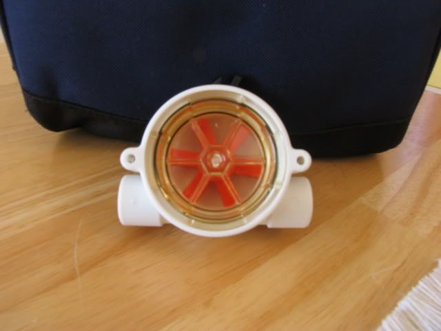
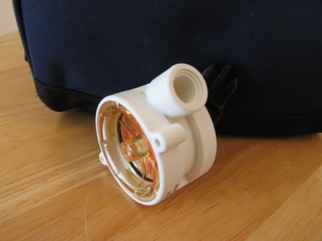
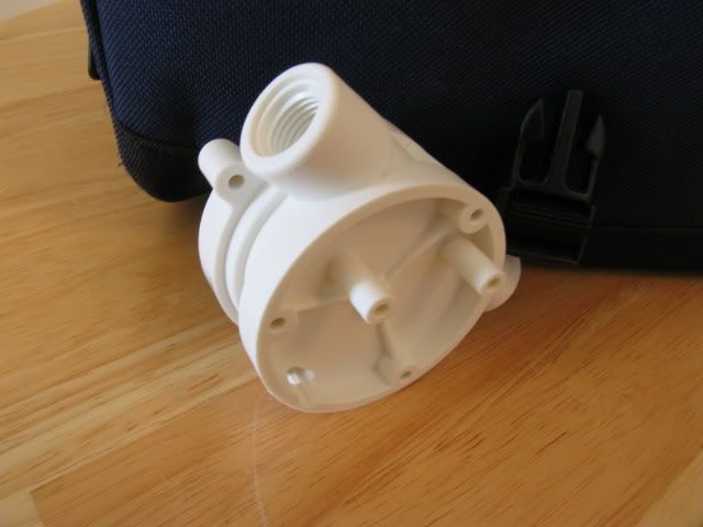
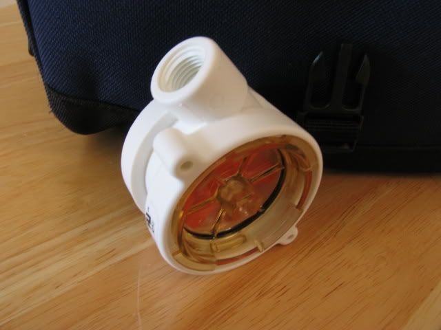
Here are the fittings installed (sans sealant)
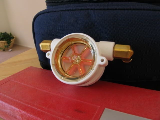
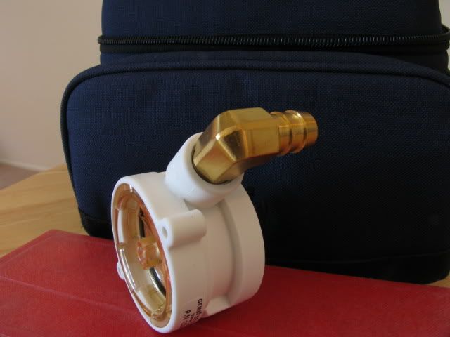
Super macro mode on my camera. Cool eh?
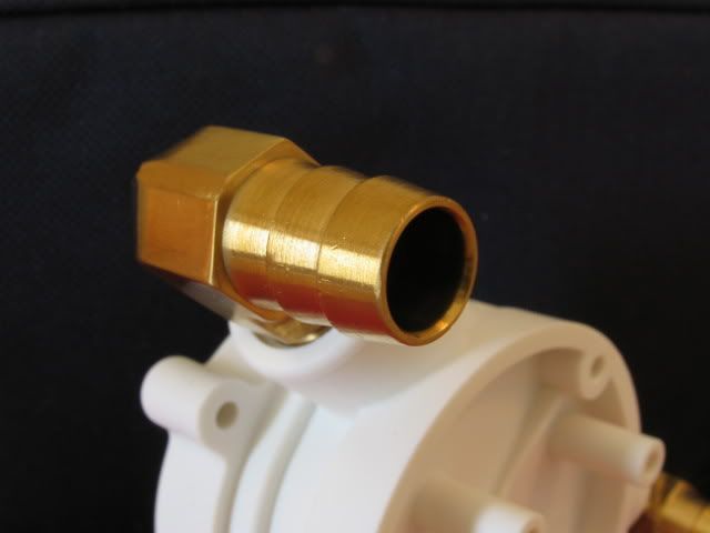
Stay tuned!
Steven
Who makes/where did you get the flow meter from?
BTW, Great looking project.
Stevennoland
Limp Gawd
- Joined
- Jan 5, 2006
- Messages
- 418
I have altered the front and back risers for the handles. All that is left is the middle. I came up with this idea. I hope the site and its owners do not mind I borrowed their logo. I only did this to pay respects to the great site that it is. Kudos to it's editors and all of you.
I had to mill this in backwards mind you. (This was also painstakingly done on a manual mill)

Tada!


Close up. No random H sighting here!


I had some mirrors made to go behind. I may tint them. I'll have to get your opinion.

With flash (sorry I forgot to clean the plexi and mirror)


Well...... What do you all think? I hope the site and it's owners and moderators don't mind. Their logo is trademarked.
Stay tuned!
Steven
I had to mill this in backwards mind you. (This was also painstakingly done on a manual mill)
Tada!
Close up. No random H sighting here!
I had some mirrors made to go behind. I may tint them. I'll have to get your opinion.
With flash (sorry I forgot to clean the plexi and mirror)
Well...... What do you all think? I hope the site and it's owners and moderators don't mind. Their logo is trademarked.
Stay tuned!
Steven
Stevennoland
Limp Gawd
- Joined
- Jan 5, 2006
- Messages
- 418
Gh()st said:Who makes/where did you get the flow meter from?
BTW, Great looking project.
Check McMaster's website under flowmeters. And thanks!
Steven
Stevennoland
Limp Gawd
- Joined
- Jan 5, 2006
- Messages
- 418
Deam said:Sorry if this was asked before, but how did you build the reservoir, and where did you get the cylindrical plastic?
Thanks, and fanastic work!
Thanks for the question Deam. I bought the plexiglass tube from McMaster, rough cut it to length. I used a lathe to turn and bore the ends. I then drilled and tapped the holes in the tube ends. I turned up the aluminum ends. Drilled the screw holes and tapped the holes for the pipe fittings. I picked up the silicone o-rings locally and put it alltogether. Easy eh?
Steven
pm me for more pics of the res
Stevennoland
Limp Gawd
- Joined
- Jan 5, 2006
- Messages
- 418
thewhiteguy said:Wouldn't a 1/2" setup be more in line with the project's title?
Most of the set-up will be 1/2". The inlets on the Konvect-o-matic radiators are only 5/16" in diameter. The DDC pumps are for these rads. The 3/8" barbs are more than enough. Thanks for asking.
Steven
Stevennoland said:I have altered the front and back risers for the handles. All that is left is the middle. I came up with this idea. I hope the site and its owners do not mind I borrowed their logo. I only did this to pay respects to the great site that it is. Kudos to it's editors and all of you.
I had to mill this in backwards mind you. (This was also painstakingly done on a manual mill)
http://i48.photobucket.com/albums/f229/stevennoland/ocpplexi001.jpg[/IG]
Tada!
[IMG]http://i48.photobucket.com/albums/f229/stevennoland/ocpplexi002.jpg[/IG]
[IMG]http://i48.photobucket.com/albums/f229/stevennoland/ocpplexi003.jpg[/IG]
Close up. No random H sighting here!
[IMG]http://i48.photobucket.com/albums/f229/stevennoland/ocpplexi004.jpg[/IG]
[IMG]http://i48.photobucket.com/albums/f229/stevennoland/ocpplexi005.jpg[/IG]
I had some mirrors made to go behind. I may tint them. I'll have to get your opinion.
[IMG]http://i48.photobucket.com/albums/f229/stevennoland/ocpplexi006.jpg[/IG]
With flash (sorry I forgot to clean the plexi and mirror)
[IMG]http://i48.photobucket.com/albums/f229/stevennoland/ocpplexi007.jpg[/IG]
[IMG]http://i48.photobucket.com/albums/f229/stevennoland/ocpplexi008.jpg[/IG]
Well...... What do you all think? I hope the site and it's owners and moderators don't mind. Their logo is trademarked.
Stay tuned!
Steven[/QUOTE]
You should get permission from Kyle and start selling those to forum members to add to their mods.
[URL=http://www.hardfolding.com?go=38&tm=33&id=1771][IMG]http://www.hardfolding.com/ftag1.php/mem/1771.png[/URL]
Stevennoland said:Thanks for the question Deam. I bought the plexiglass tube from McMaster, rough cut it to length. I used a lathe to turn and bore the ends. I then drilled and tapped the holes in the tube ends. I turned up the aluminum ends. Drilled the screw holes and tapped the holes for the pipe fittings. I picked up the silicone o-rings locally and put it alltogether. Easy eh?
Steven
pm me for more pics of the res
Thanks for the reply! PM sent.
Stevennoland
Limp Gawd
- Joined
- Jan 5, 2006
- Messages
- 418
Here is the front middle riser (as apposed to the back middle riser) with the slot machined for the HardOCP logo plexi. Enjoy!

Close-up

Although it might not be evident in these pictures, the plexiglass is flush with the front of the riser

See my camera in the reflection?


I still haven't found anything to put in the other plexi. Ideas?
I'm currently working on a huge project for the front door of the case. I'll give you a hint, think custom made passive radiator.
Stay tuned!
Steven
Close-up
Although it might not be evident in these pictures, the plexiglass is flush with the front of the riser
See my camera in the reflection?
I still haven't found anything to put in the other plexi. Ideas?
I'm currently working on a huge project for the front door of the case. I'll give you a hint, think custom made passive radiator.
Stay tuned!
Steven