freddiepm61
Gawd
- Joined
- Oct 19, 2004
- Messages
- 836
SN for stevennoland?
[H]ardIForum?
f
[H]ardIForum?
f
Follow along with the video below to see how to install our site as a web app on your home screen.
Note: This feature may not be available in some browsers.
freddiepm61 said:SN for stevennoland?
[H]ardIForum?
f
DeathMan said:you...
are...
a god...
most incredible work i've seen on a case... so much attention to every detail...
love the idea w/ the ccfl's in the handles too
el rolio said:dude, on the pumps use the top inlet port instead. buy a allen wrench if you have to. its woorth it big time. lots more flow/head. i did the exact thing you did. specced a 18W updated DDC from dangerden, plexi top from voyuermods, and 1/2" barbs from EK waterblocks, all for less than the cost of buying the full thing direct from alphacool in germany.
Stevennoland said:Also, the longer the water stays in the rad, the more chance it has to cool (A higher flow rate would contradict this idea). Thanks for the notion though.
Steven
Demon_of_The_Fall said:That's untrue, higher flow rate always means better cooling.
DeathMan said:you...
are...
a god...
most incredible work i've seen on a case... so much attention to every detail...
love the idea w/ the ccfl's in the handles too
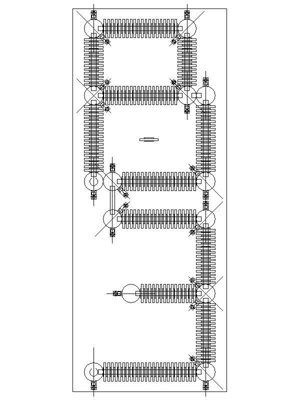
azn_bboy07 said:great works man!! cant wait to see the whole log complete. howeveri have a favour to ask: how does that giant radiator work? ( about the water flow, how the water got cool down) since i'm a noob on wc.
cheers
ryan_975 said:i've been watching this thread for a while now, great work. I wish I could do something like that. Anyway have their been any updates as of late?
Ryan


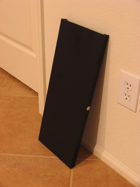


Viperlover said:You absolutely HAVE to weigh this thing! See if you can break the 100lb marker....
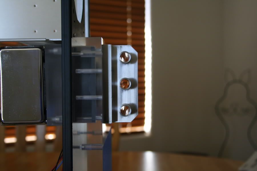
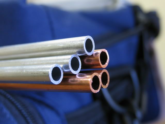
stormshadow said:so each of the doorad fins will have three holes for three pipes if i understand correctly...
but on the CAD of the B3 design, i only saw one pipe going through the fins...
could you clarify?
(great work btw)
kydsid said:Just finished reading all 18 pages
There isn't a word in the English language I could use to describe this project. Just don't stop working!
THE BEASTlinusthepenguin said:This mod speaks QUALITY... right up there with bonz and topnurse
/subscribed