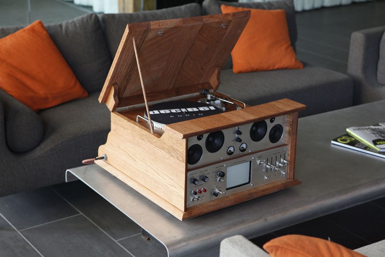
October 2013 Update: PROJECT COMPLETE! View Page 2 for final images, AND visit audio.toddkumpf.com for a video and even more photos & info about each aspect of the project.
----------------------------------
(Original build log below)
----------------------------------
This has been in design and production for about 4 months, on and off, but i'm finally now with enough progress and momentum to warrant a proper work log.
It's a stereo/boombox that streams music over WiFi and also plays vinyl records. It has a built in music visualizer, an analog graphic EQ, and a few other tricks up it's sleeve. It's meant to be an all-in-one audio playing device with dynamic options for any music playing scenario. Here's a breakdown of it's features:
WHAT IT DOES:
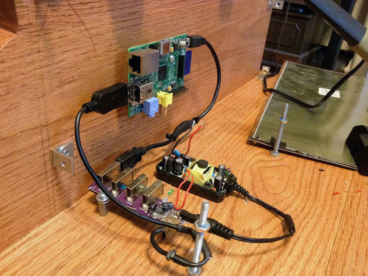
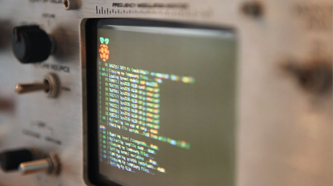
01) Using a Raspberry Pi, streams music over WiFi from your mobile device (using ShairPort, functions like Apple AirPlay)
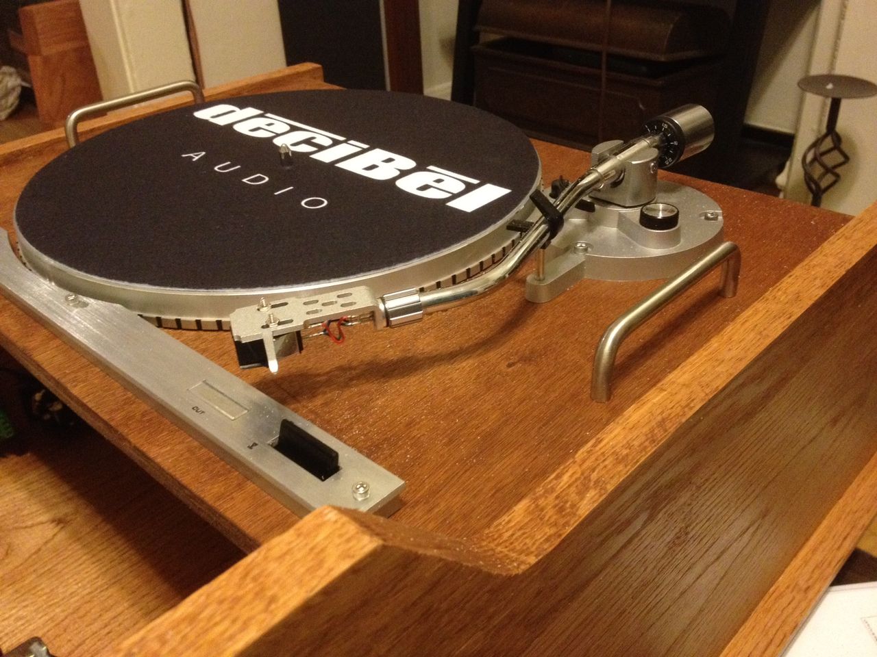
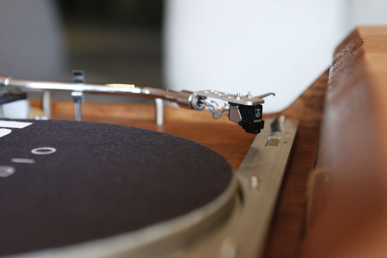
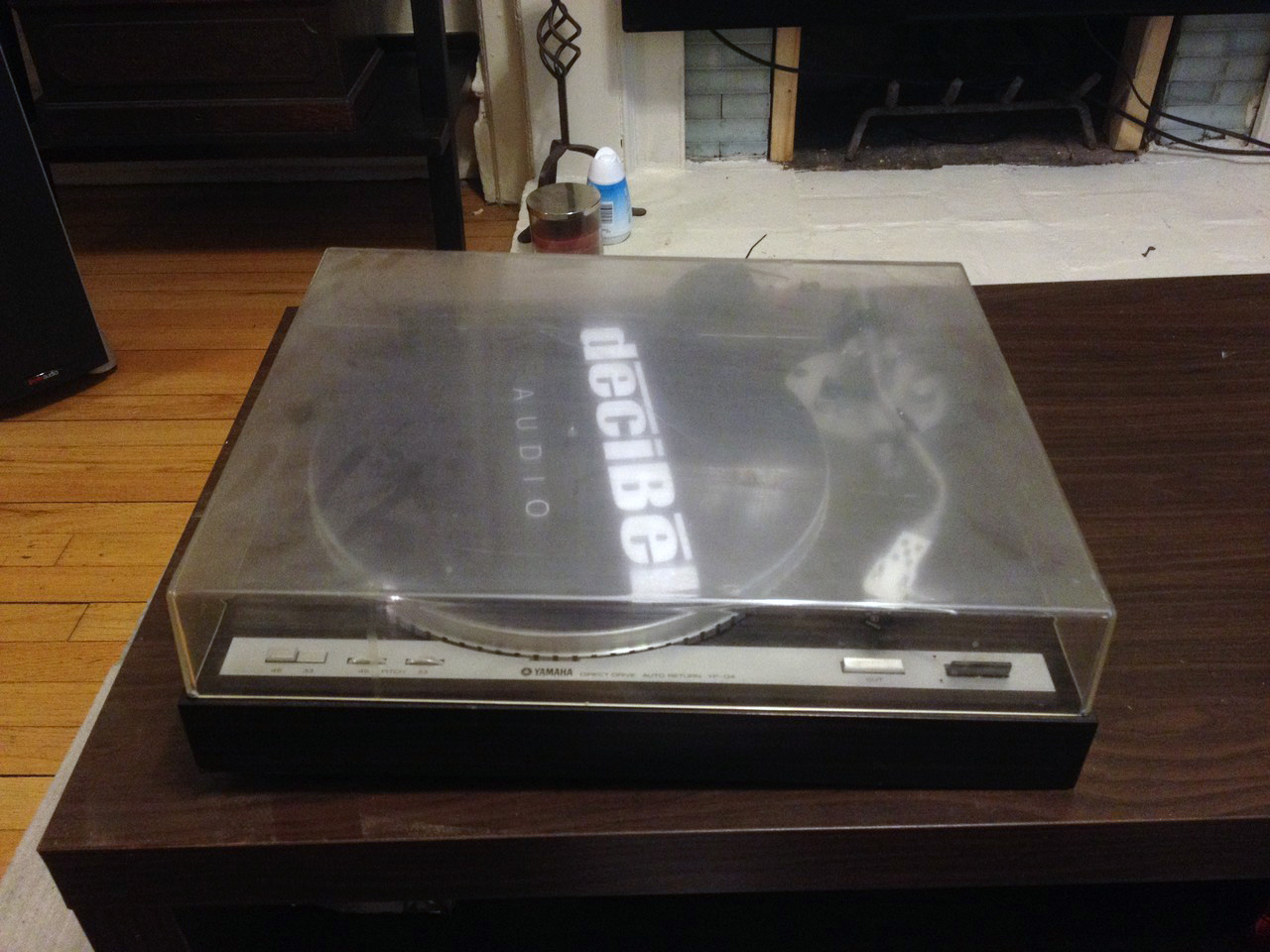
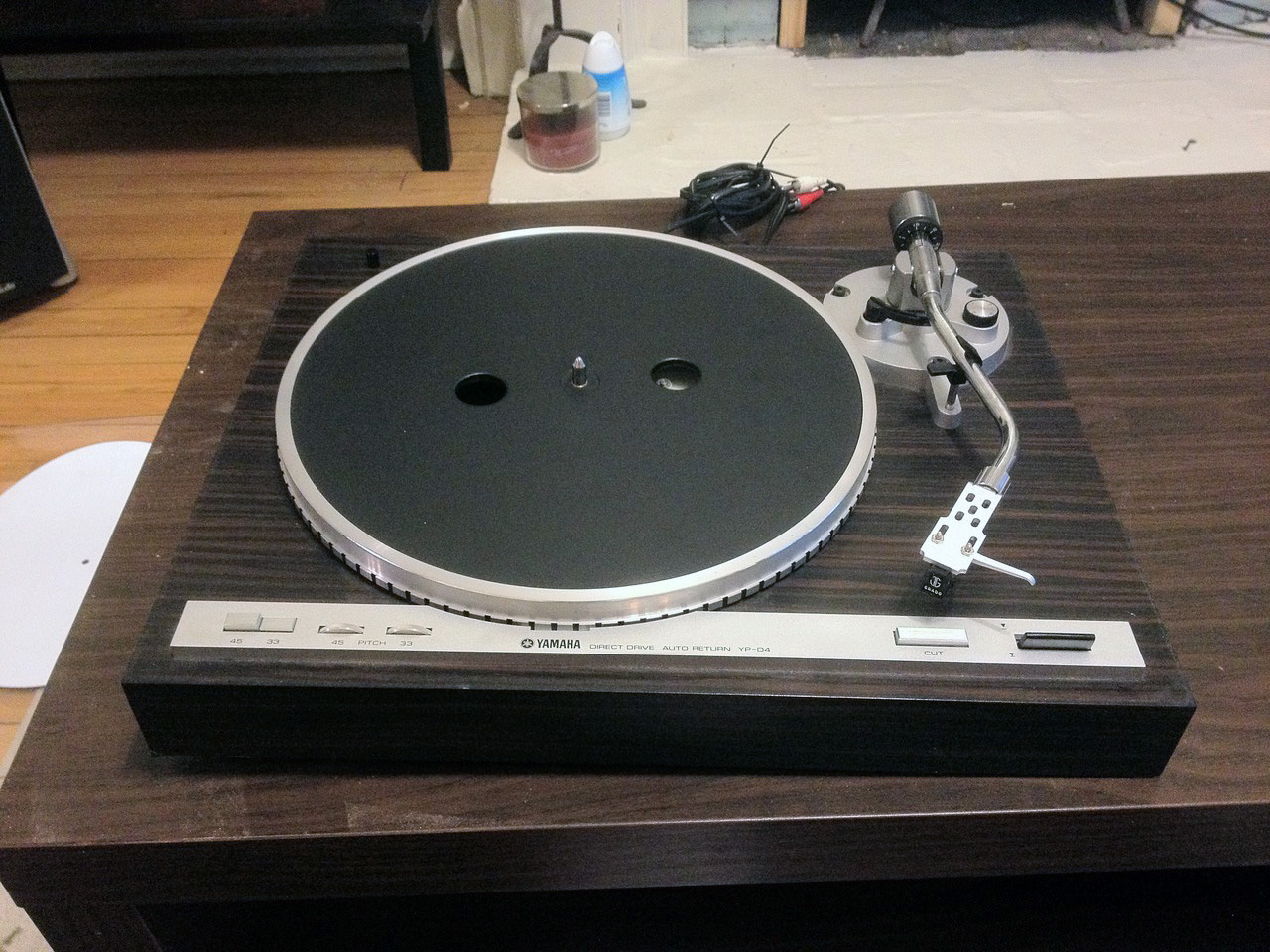
02) Has a built-in turntable to play vinyl records (parts adapted from a vintage Yamaha YP-D4)
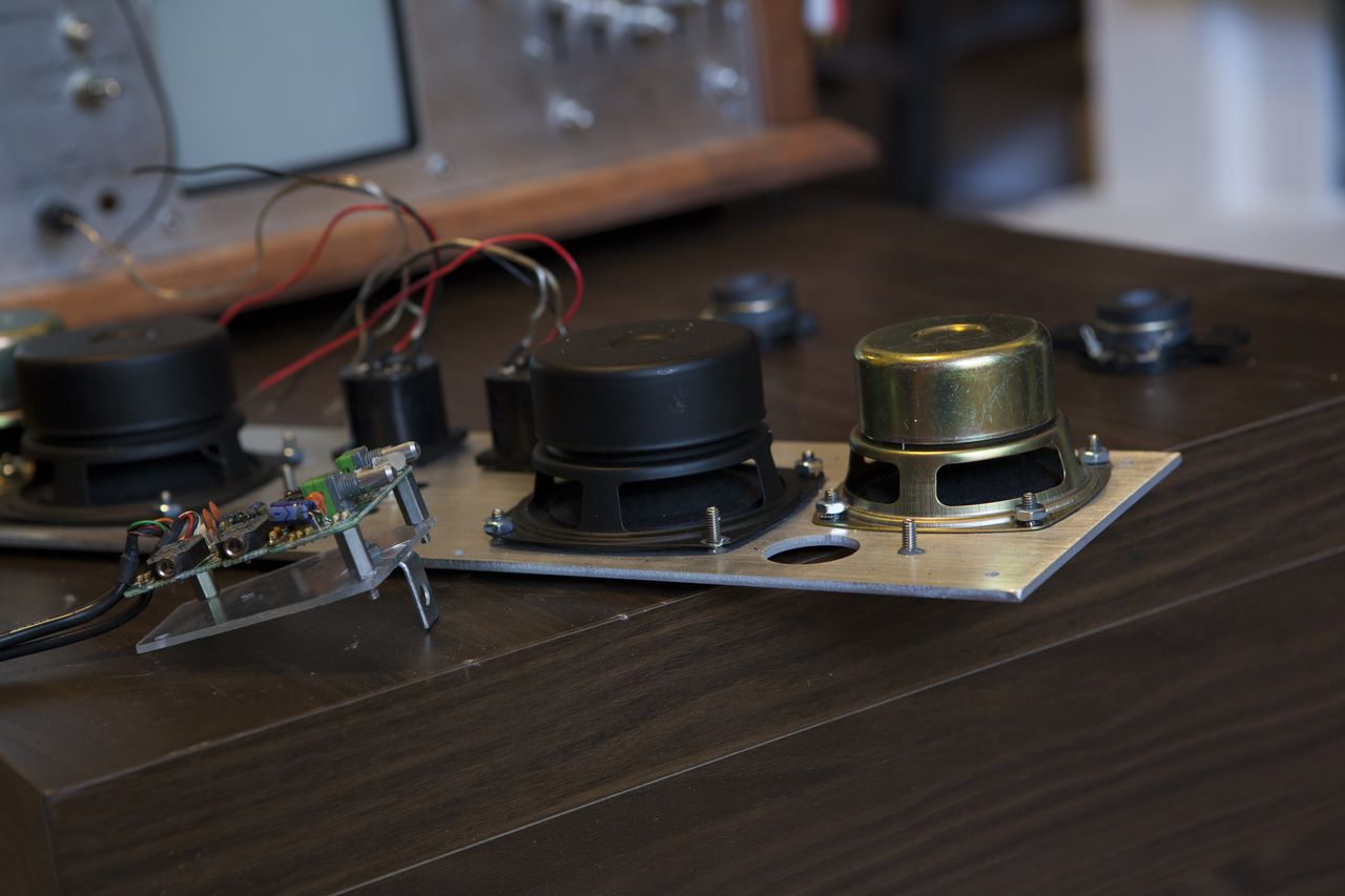
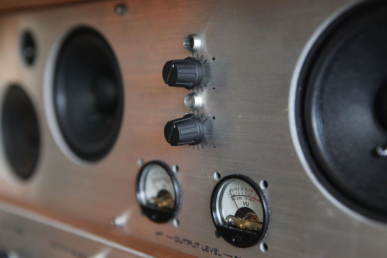
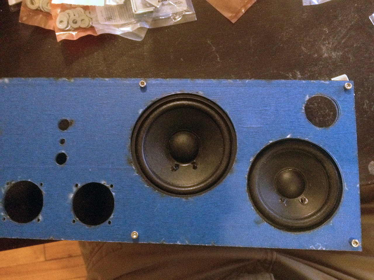
03) Has four built in mid-range speakers, two tweeters, and one subwoofer (parts adapted from Klipsche ProMedia 2.1, with two additional speakers)
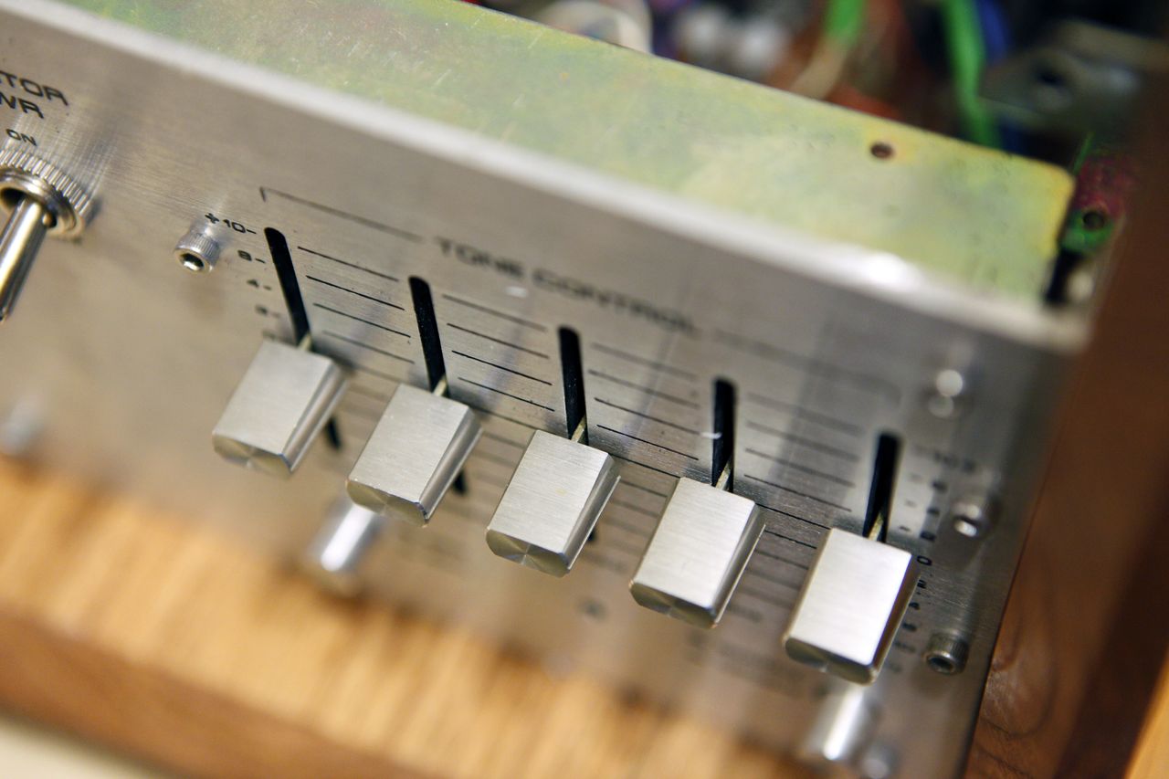
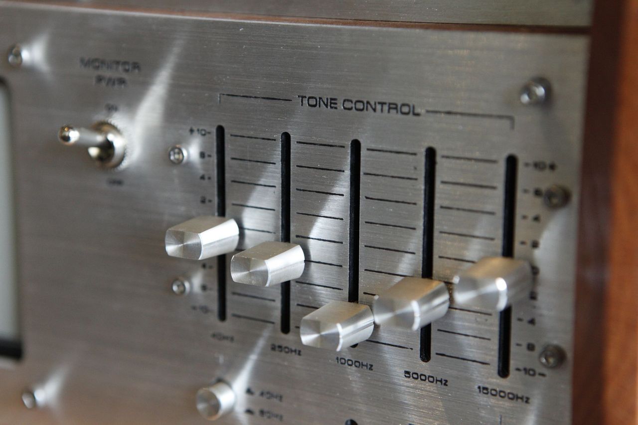
04) Has an analog graphic equalizer with 7 effective frequency bands (parts adapted from JVC SEA-10 vintage EQ)
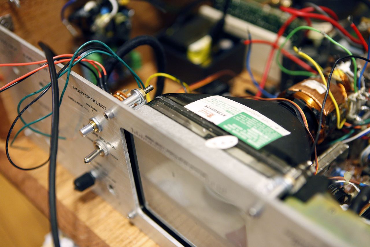
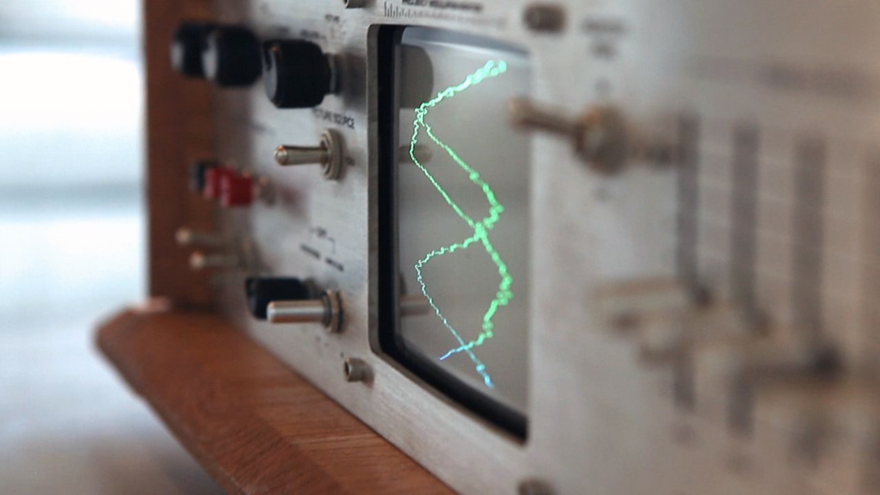
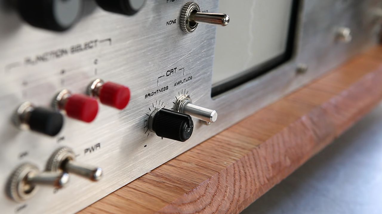
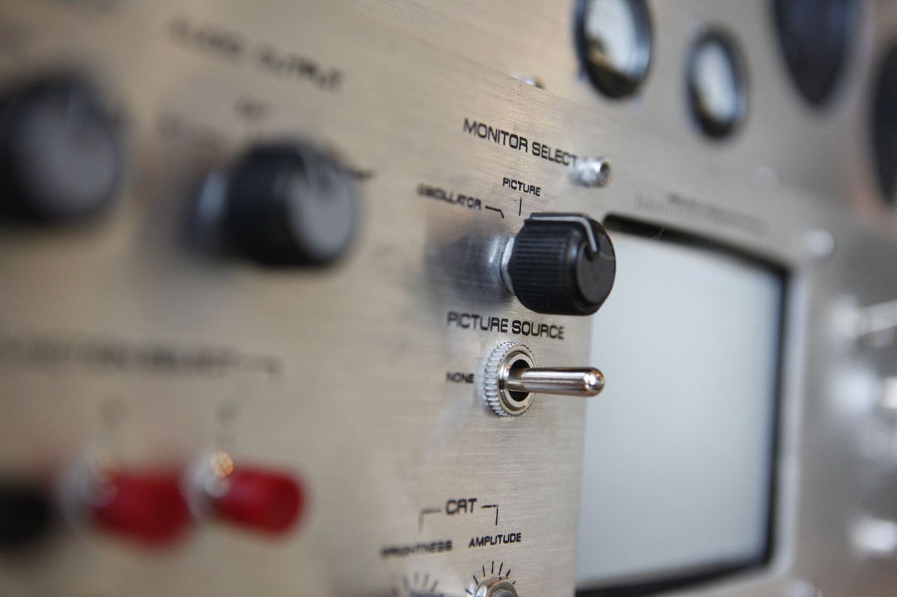
05) Has a 5" CRT monitor that functions as an analog music visualizer, behaving similar to an oscilloscope
06) Can switch output from internal speakers to external device (via RCA cables)
07) Can also output wirelessly, transmitting over a medium which is still TBD. Will be either over WiFi using the Raspberry Pi, or to a specific FM band using a mini FM transmitter.
08) Can take auxiliary input from any device via 1/8" audio jack.
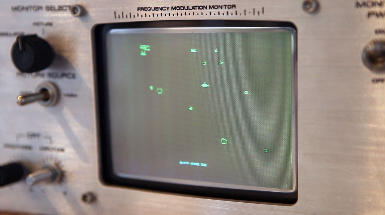
09) The Raspberry Pi can be switched into arcade mode, using AdvanceMAME emulator to play classic arcade games on the 5" CRT. Current functional games include PacMan, Asteroids, and Space Invaders using a custom USB controller pad.
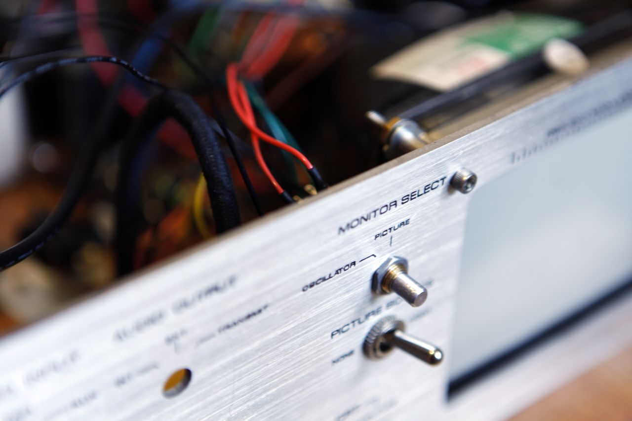
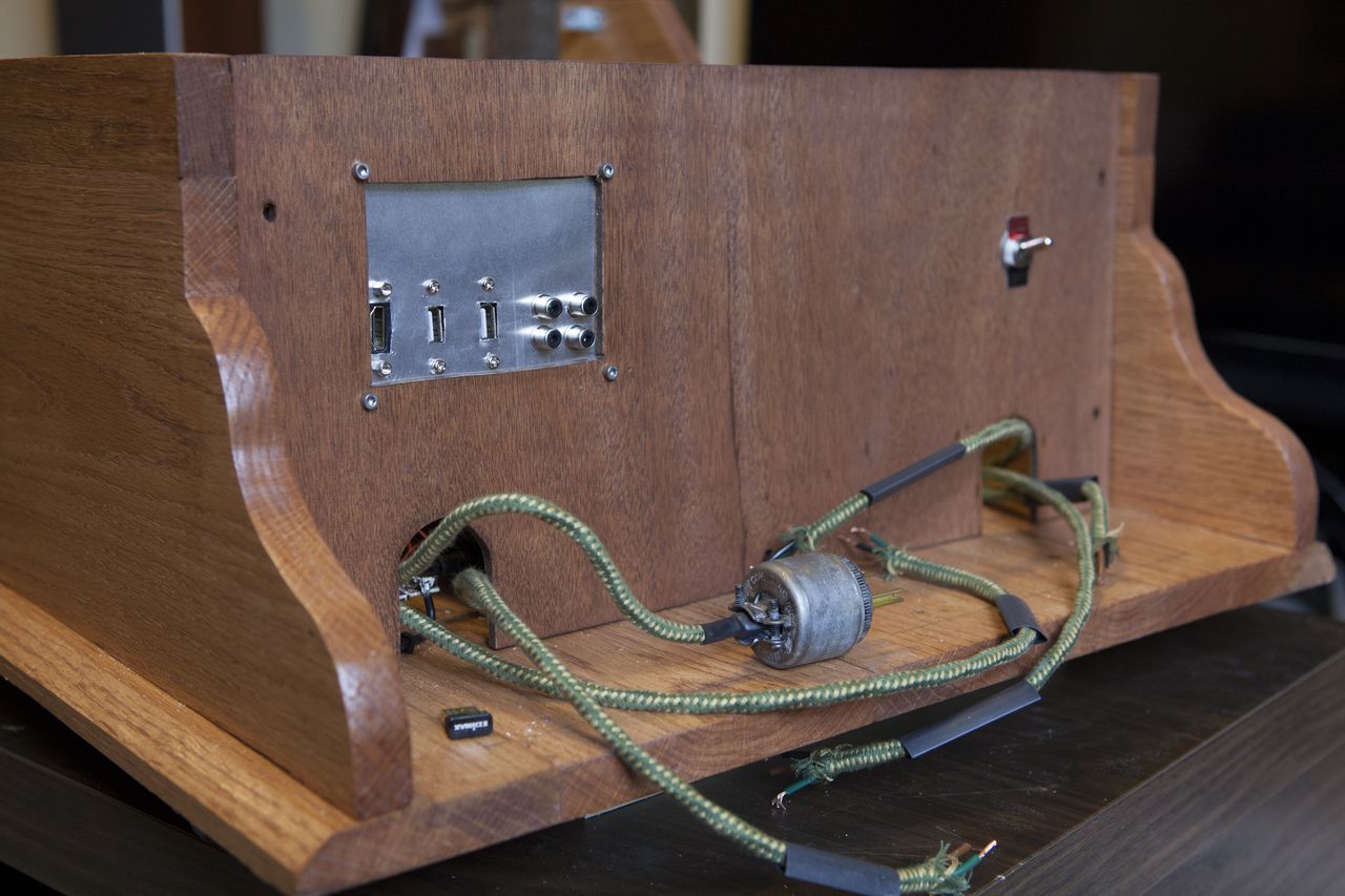
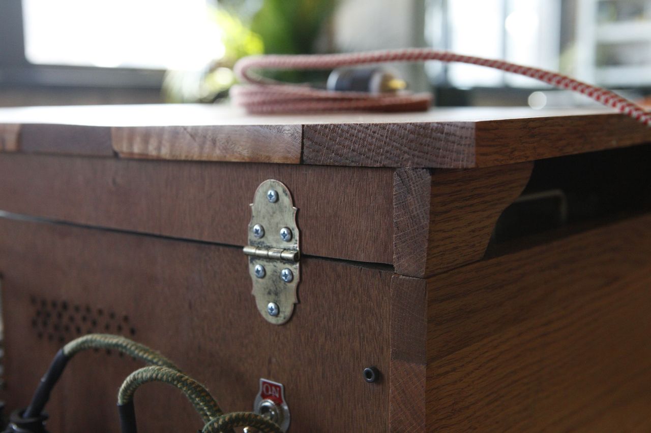
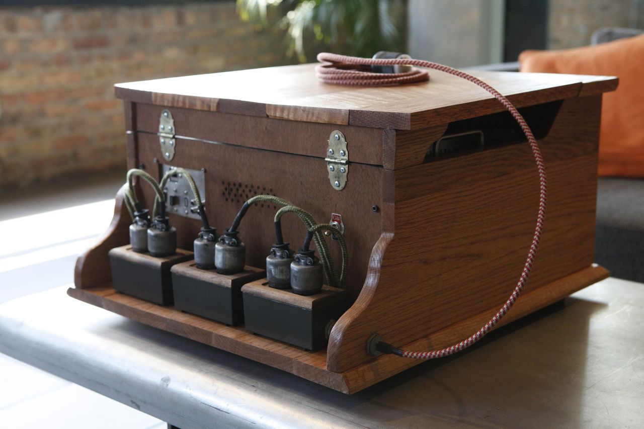
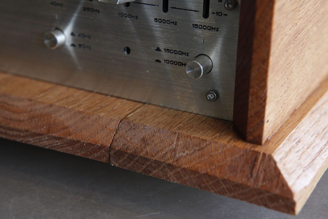
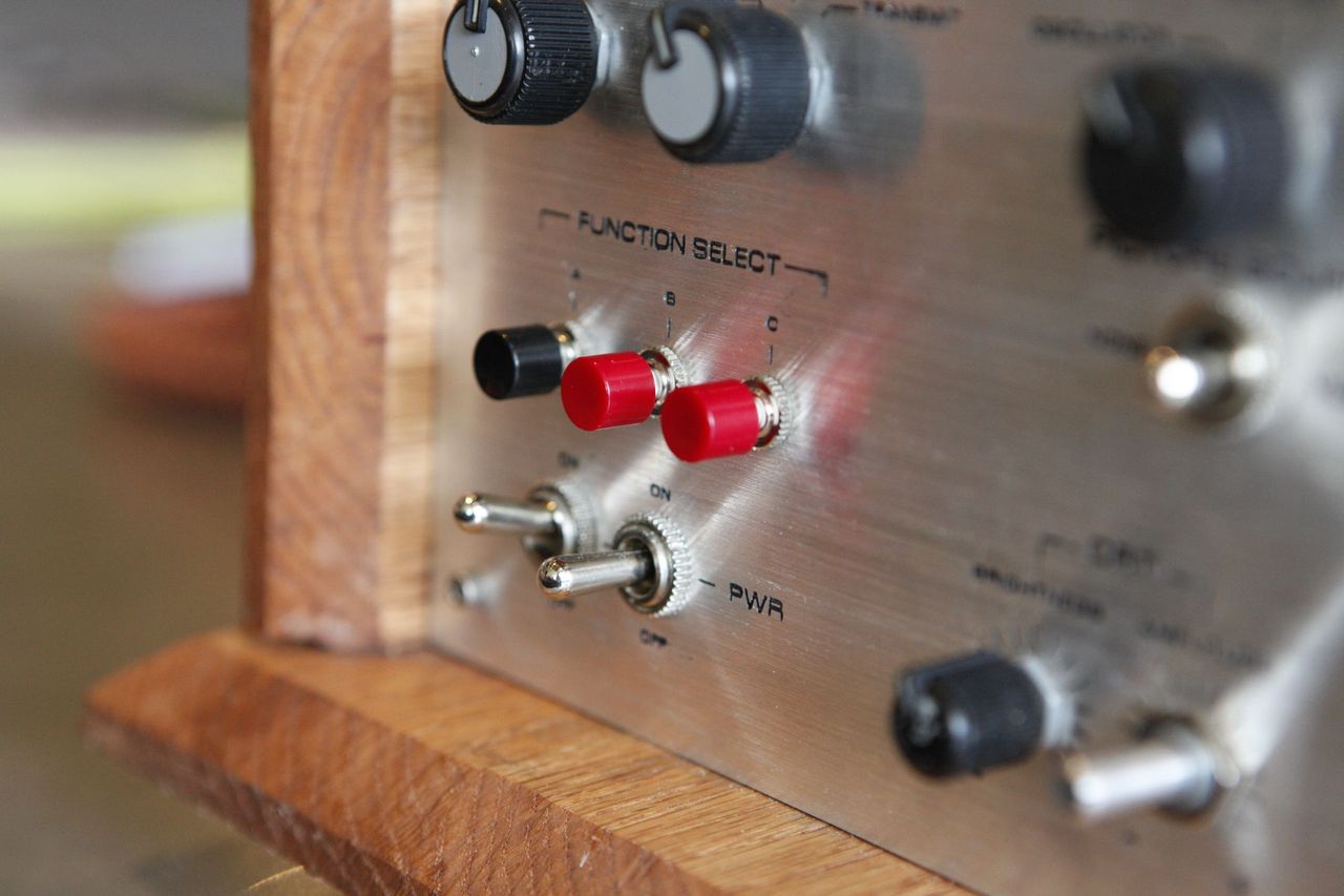
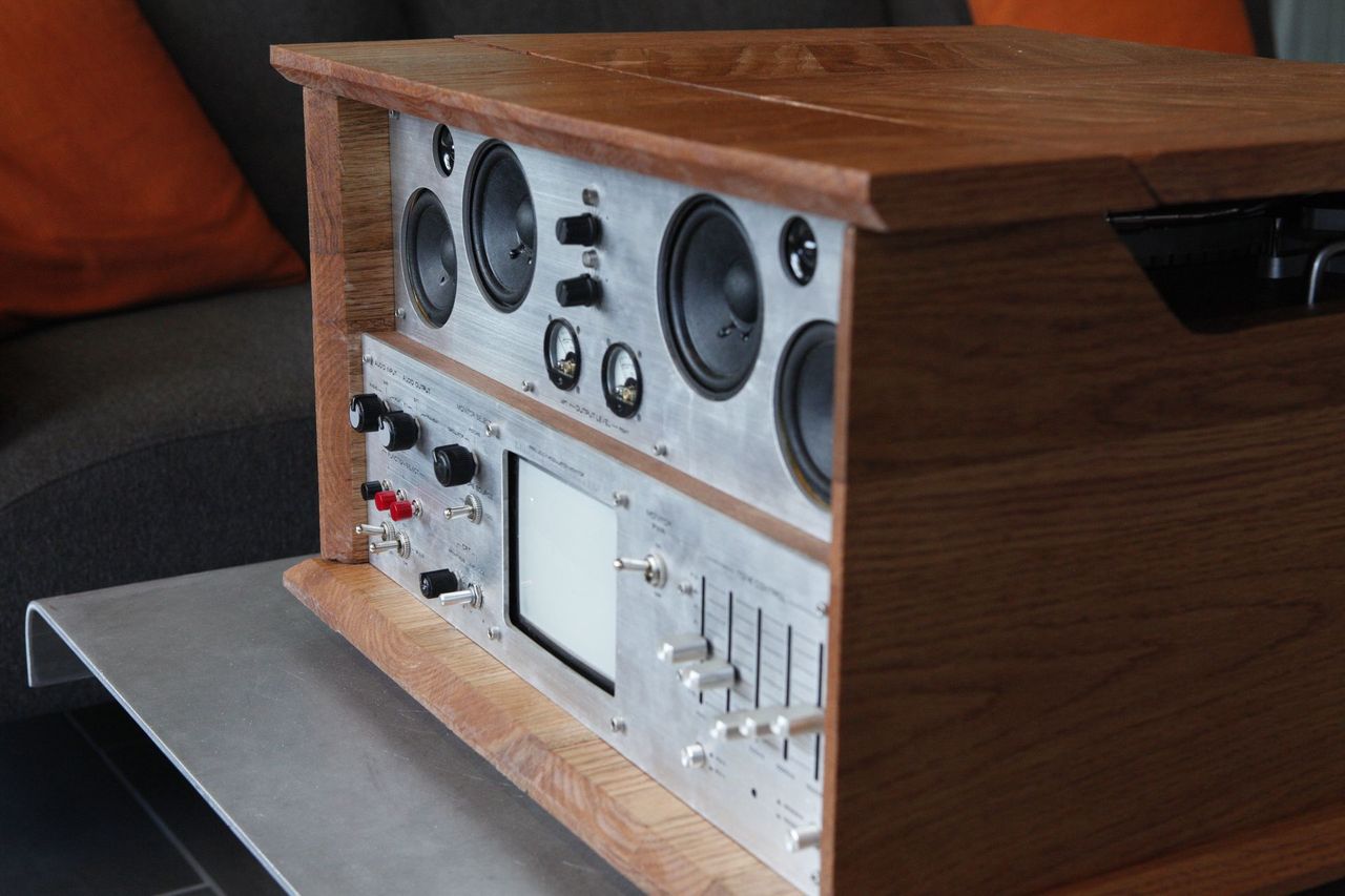
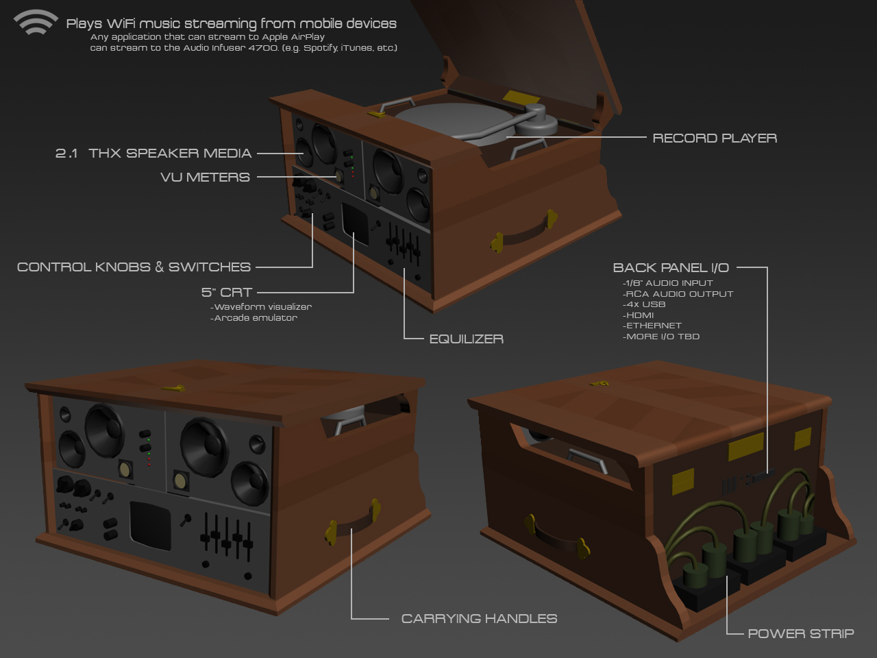
The visual design is very heavily inspired by vintage HiFi equipment. Its housed in a wooden case, and has a brushed aluminum faceplate with heavy-duty switches and knobs.
Here's my 3D mockup of the physical design:
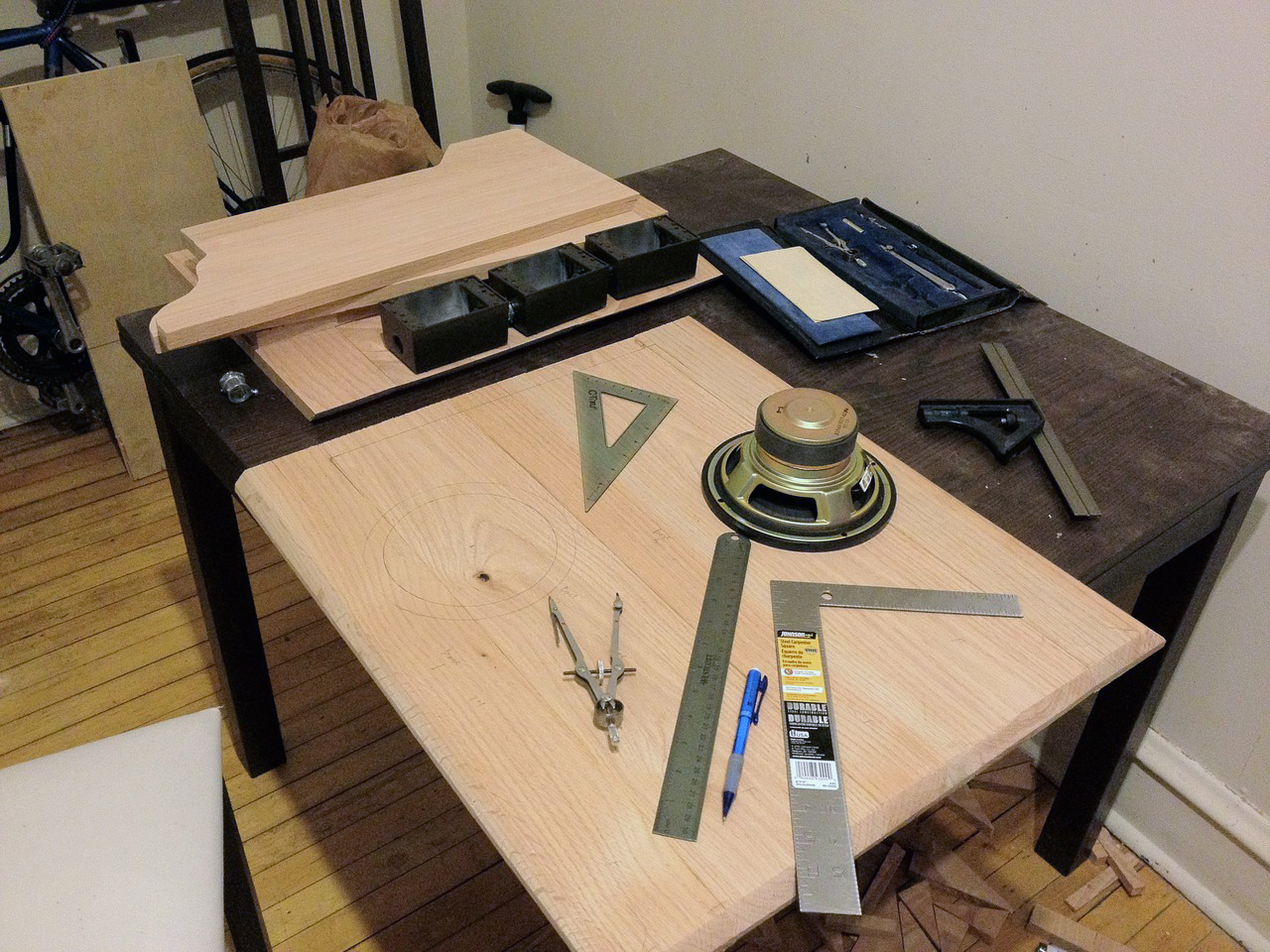
I first began by collecting items i'd need.
Here's a first test using the Klipsche ProMedia stereo set, the JVC EQ, and the 5" CRT:
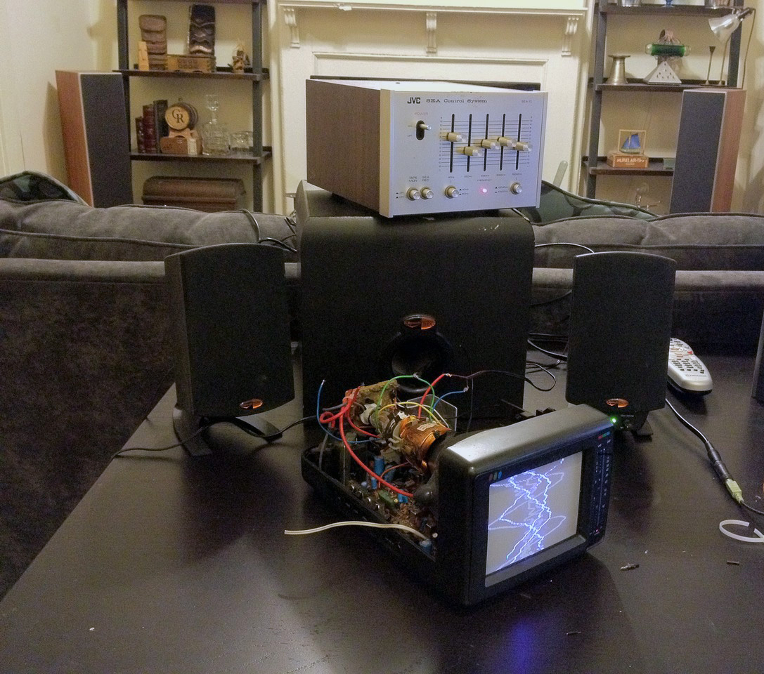
I knew I wanted a visualizer for this project. I wasn't able to find any good looking software based visualizers that functioned on Raspian Wheezy (the default Raspberry Pi OS; I'm a Linux newb), but I happened upon this Instructables tutorial on how to turn a CRT monitor into an analog oscilloscope: [link]
Surprisingly, all it takes is a couple of wire snips. CRT monitors have two sets of wires that run to the tube: vertical coils and horizontal coils. The combination of the two produces the X/Y grid of pixels you see. To turn a cathode tube into a crude oscilloscope, all you do is connect the horizontal coil inputs to a generic speaker wire output. It really is as simple as that. The audio sent through the speaker wire will drive the horizonal coils to jump around depending on the frequency and volume, giving you a really mesmerizing visualization of your music.
Here's a video of the CRT oscilloscope visualizer in action: [photo will link out to vimeo video]

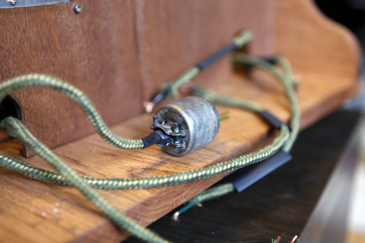
I also recorded a video showing waveforms as I play with an analog synthesizer (actually it's just the Moog Google Doodle): [vimeo video link]. In this video you also see the demonstration of how varying volumes effect the amplitude. For my stereo, I've fixed a potometer to the speaker wire input, offering an adjustment to the amplitude without compromising the volume output. This is useful because I found it can often be visually desirable to reduce the wave amplitude (i.e. spazzyness) in high volume scenarios.
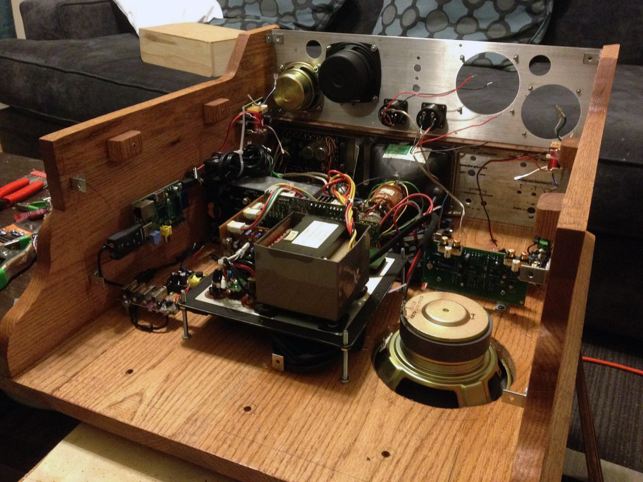
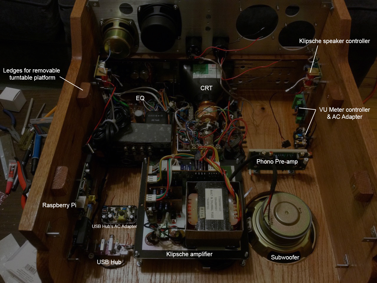
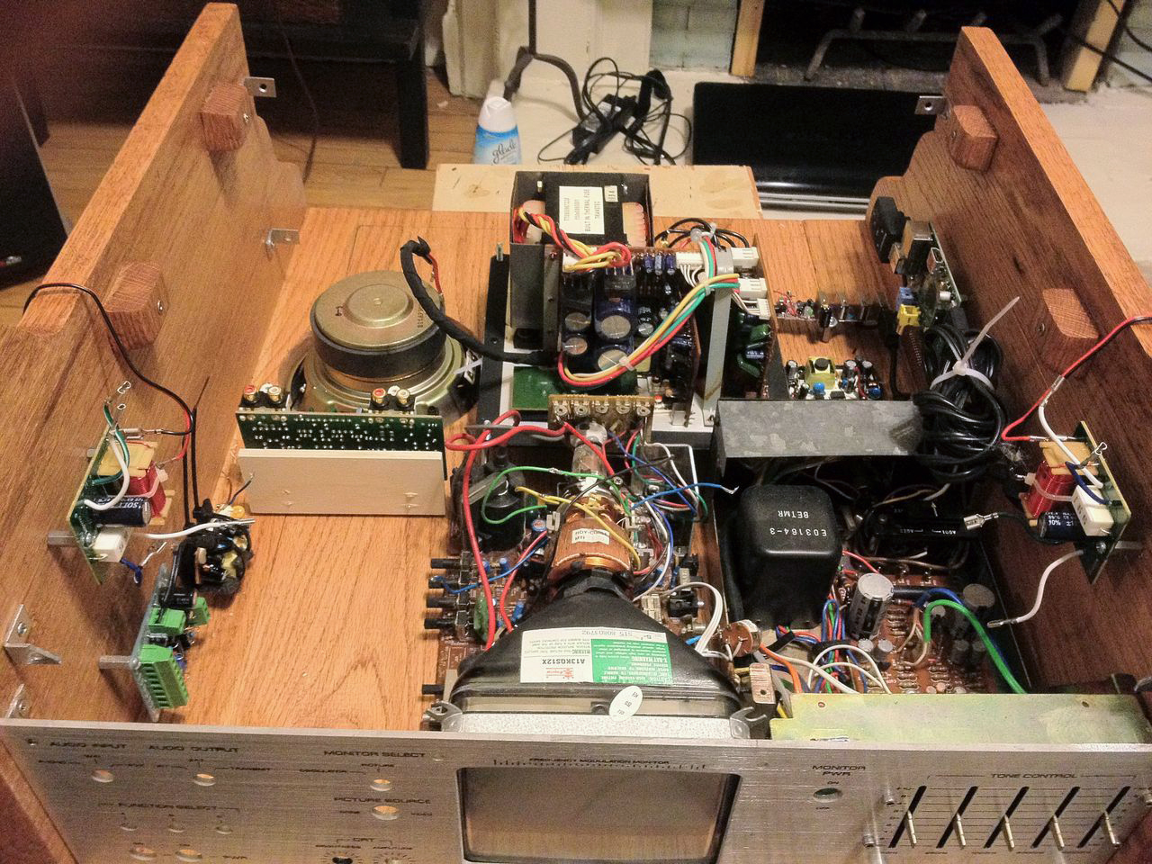
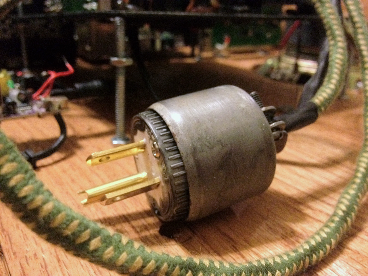
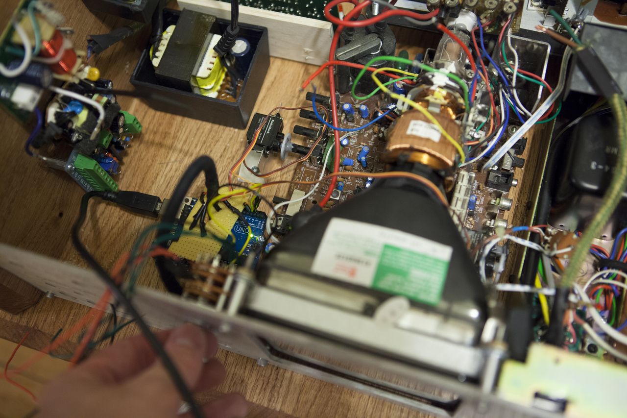
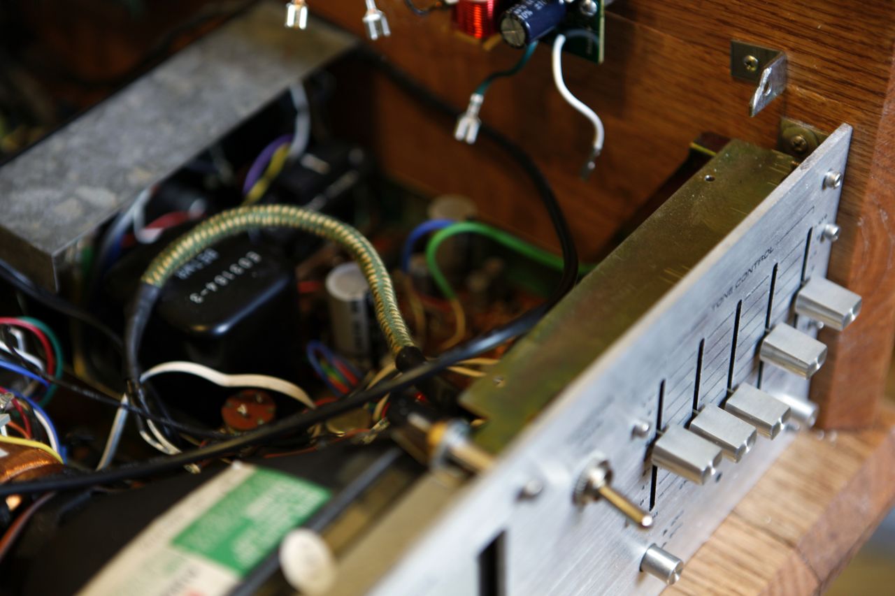
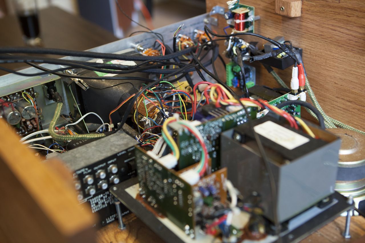
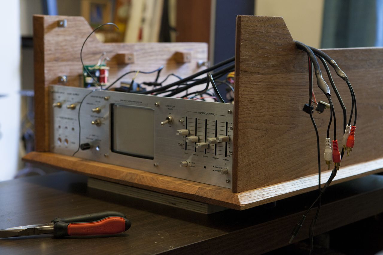
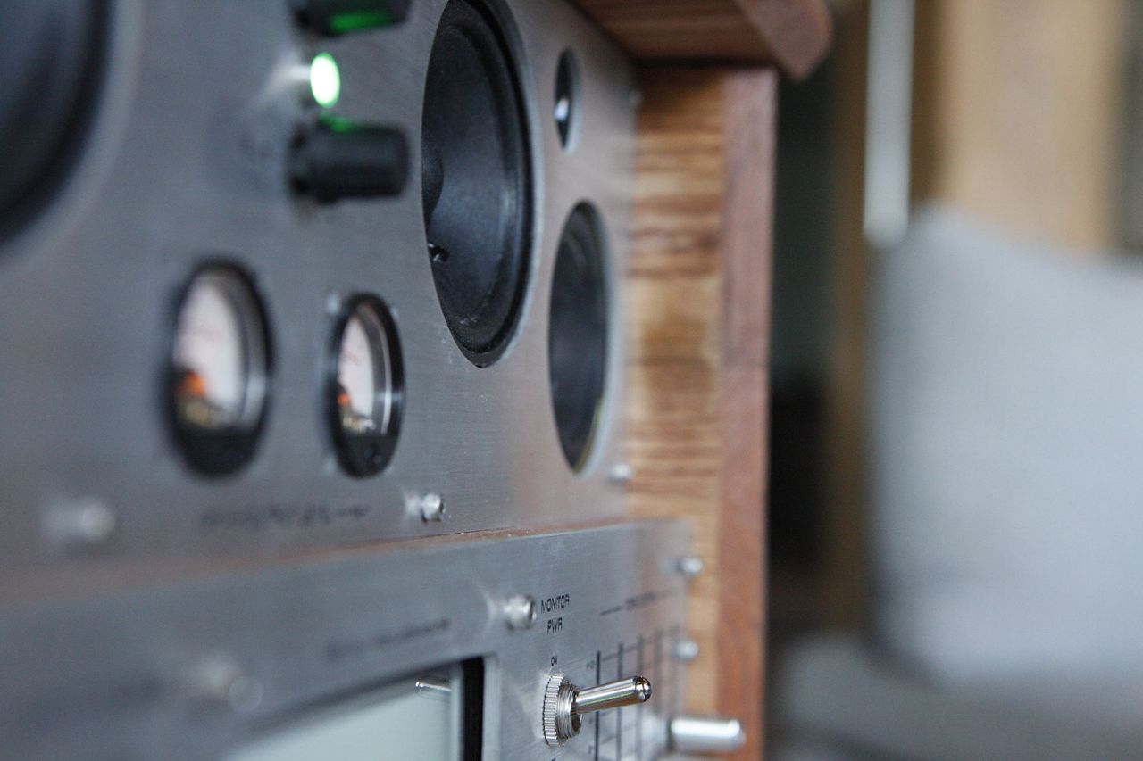
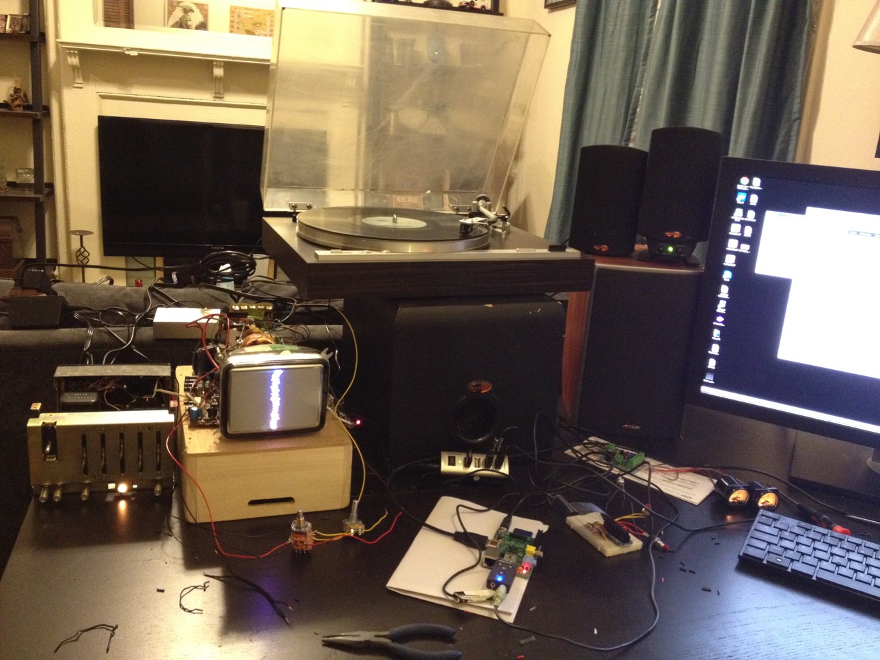
A little bit more work and I have a working prototype of all the electronic components:
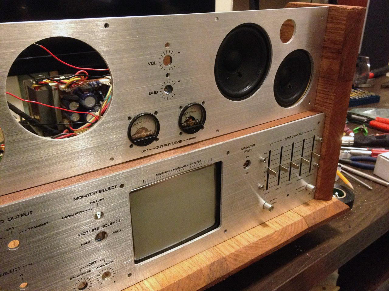
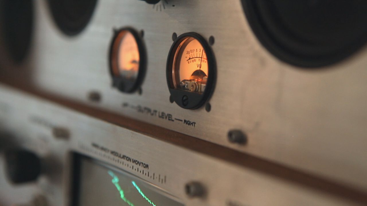
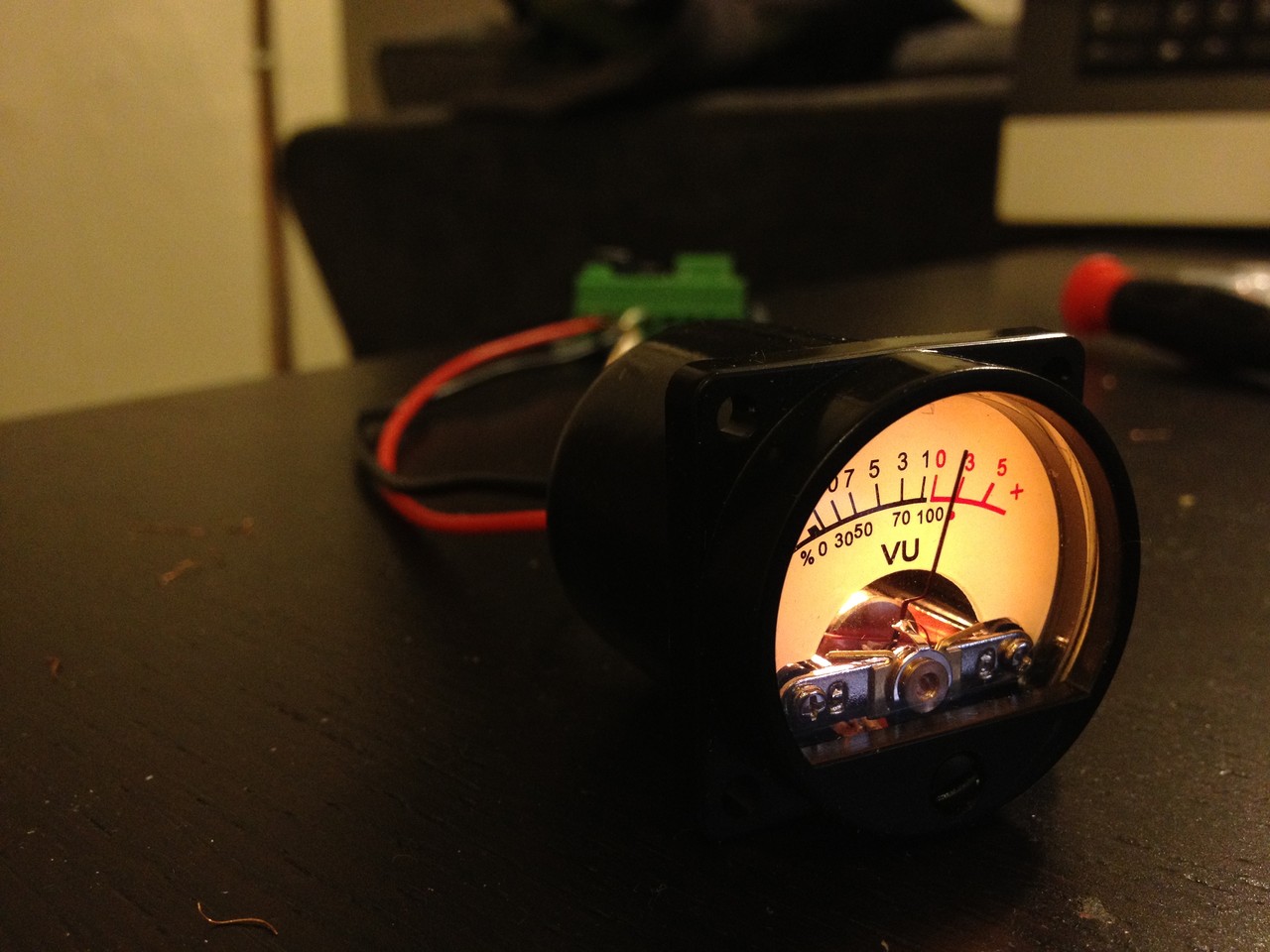
Here's a closeup of the VU meters, purchased on ebay from Japan! There will be one for LEFT and one for RIGHT channels
Now it's time to build the case. Like I said, it will be heavily inspired by vintage HiFi equipment like this Marantz amplifier, for example.
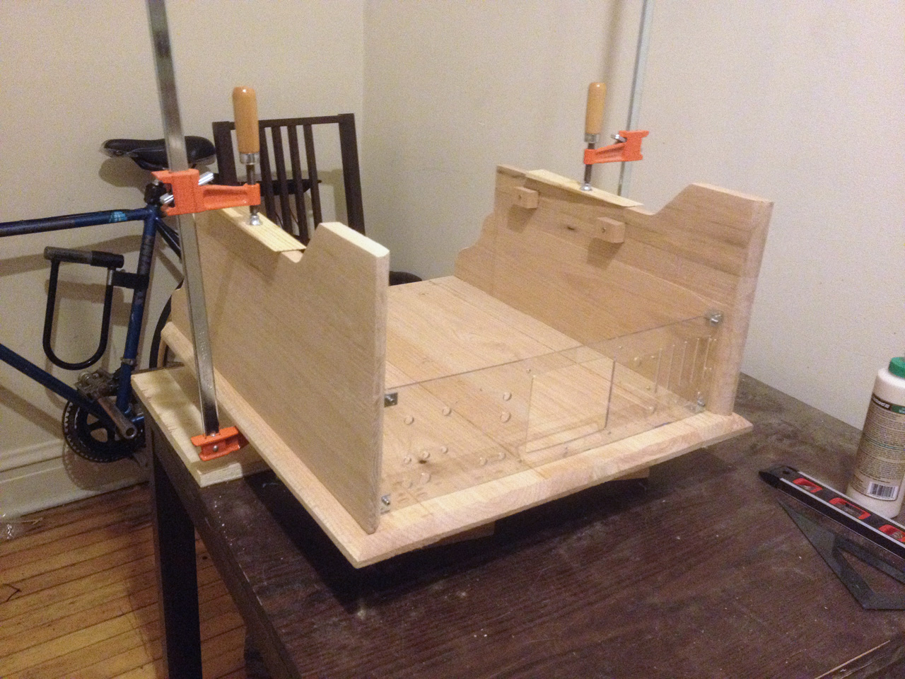
I live in the city of Chicago, so I'm limited to what I can accomplish in my 1BR apartment, with no outdoor space. My kitchen and my living room are my work spaces:
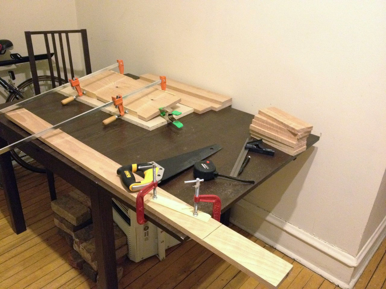
Never the less, I use hand saws, hand files, a jig-saw, Dremel, and cordless drill, and old fashion engineering to make it happen little by little:
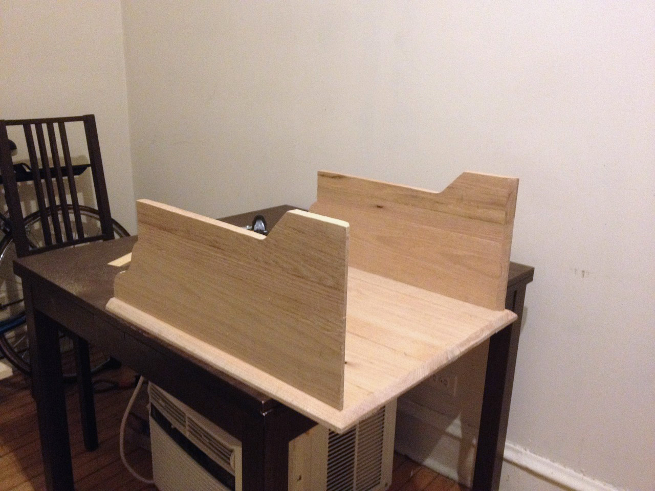
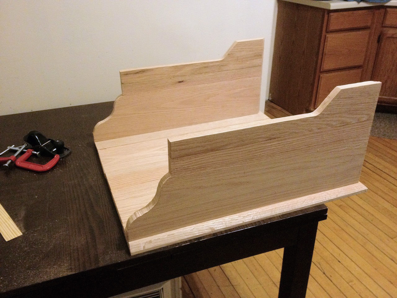
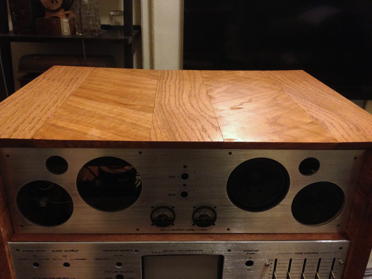
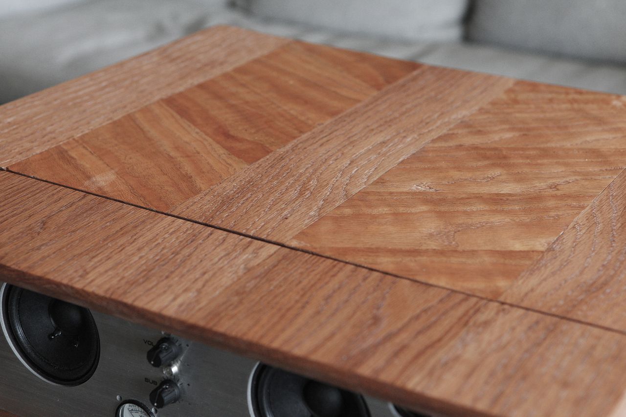
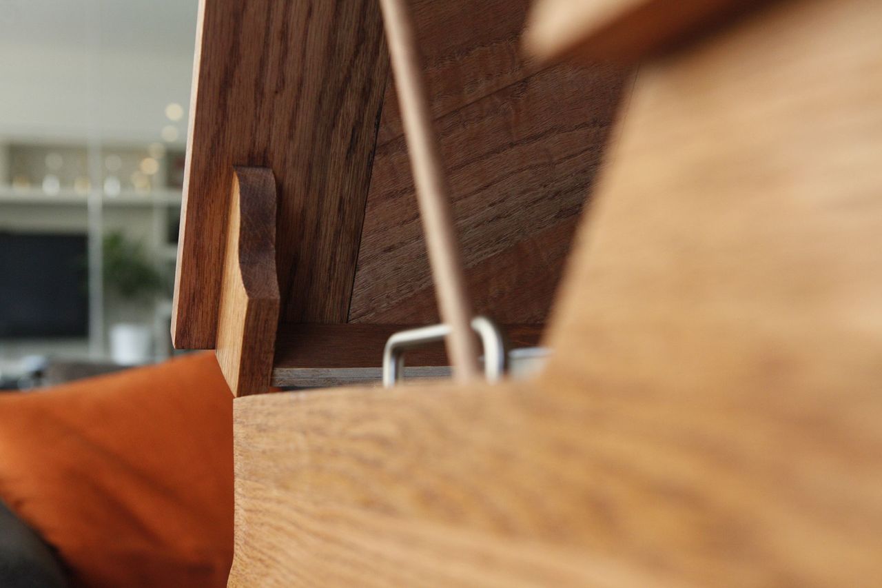
For the top, which will be a hinged lid covering the record player, I wanted to give it a slight decorative touch. I found some Red Oak with a cool marble pattern in it, so I decided to use that as angled slice insets:
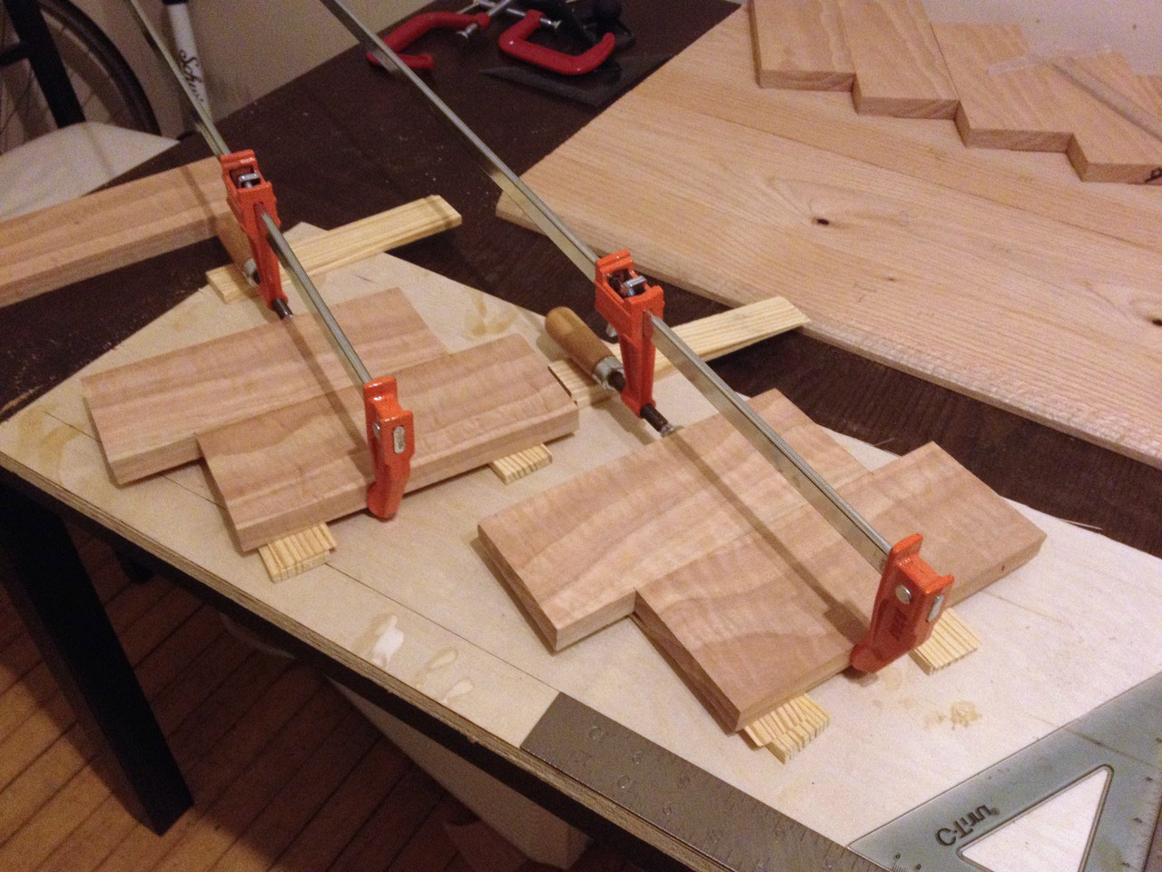
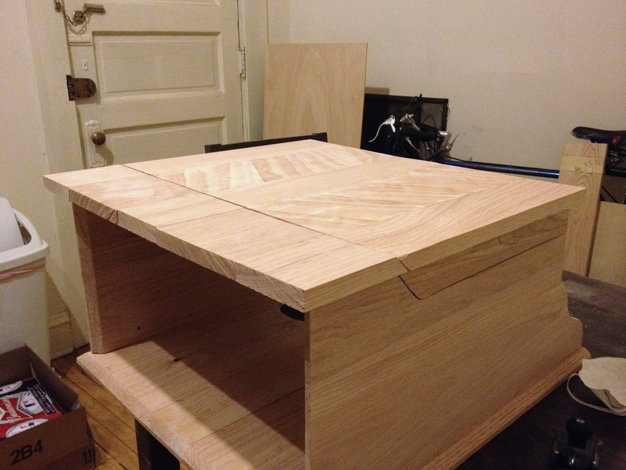
Here it is all glued together:

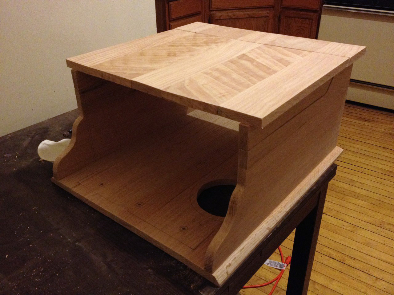
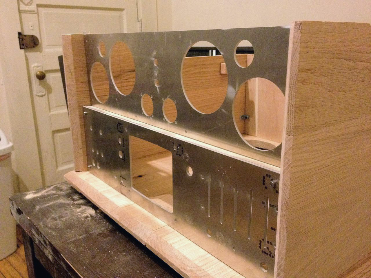
A mock-up of the case coming together: (please refer back to the [3D design image] for imaginative extrapolation purposes)
For the front, I really wanted a nice brushed aluminum face-plate to house all the switches and stuff. Since I don't have access to a CNC or other mill equipment, I found this awesome internet resource BigBlueSaw.com which will take your CAD drawing (or Illustrator or other vector image) and cut it out of various materials for you including acrylic, aluminum, steel, wood, and leather.
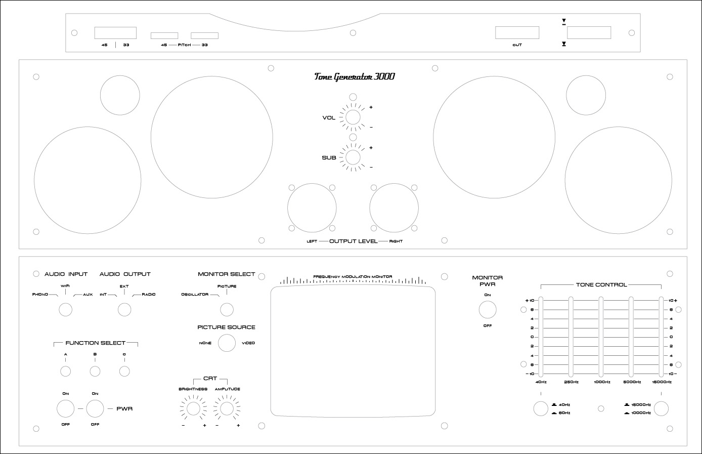
I started by designing a faceplate in AutoCAD:
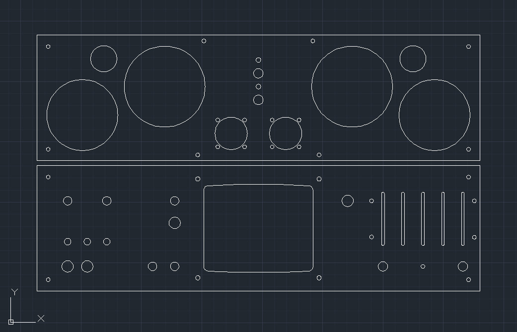
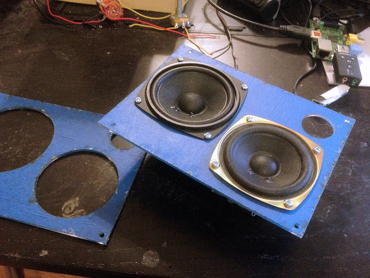
I first had Big Blue Saw cut me a prototype out of acrylic so I could test fit my size and mounting holes (which I laid out using a ruler, my eye, and best judgement)
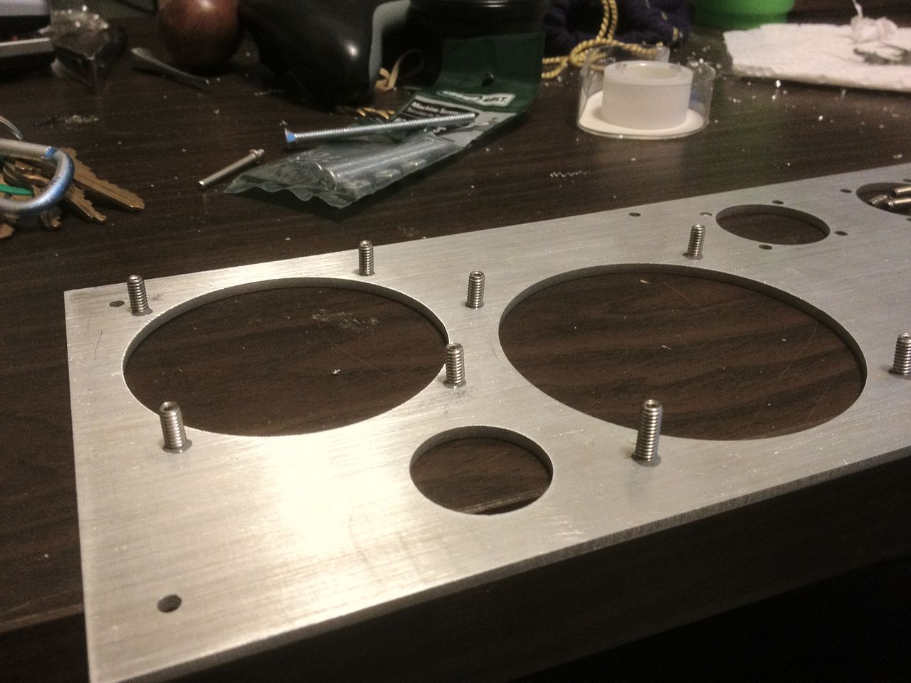
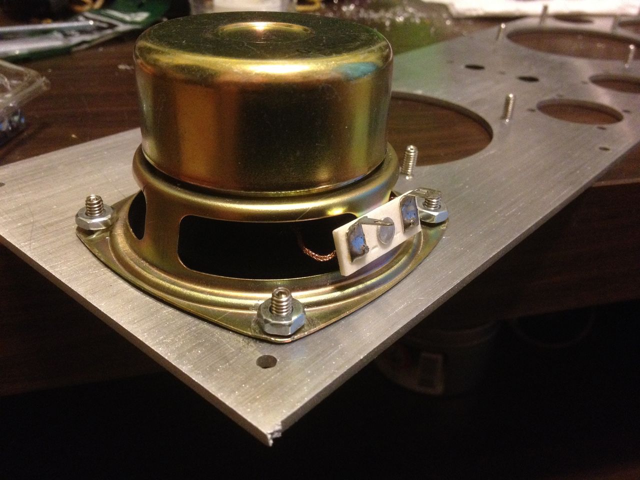
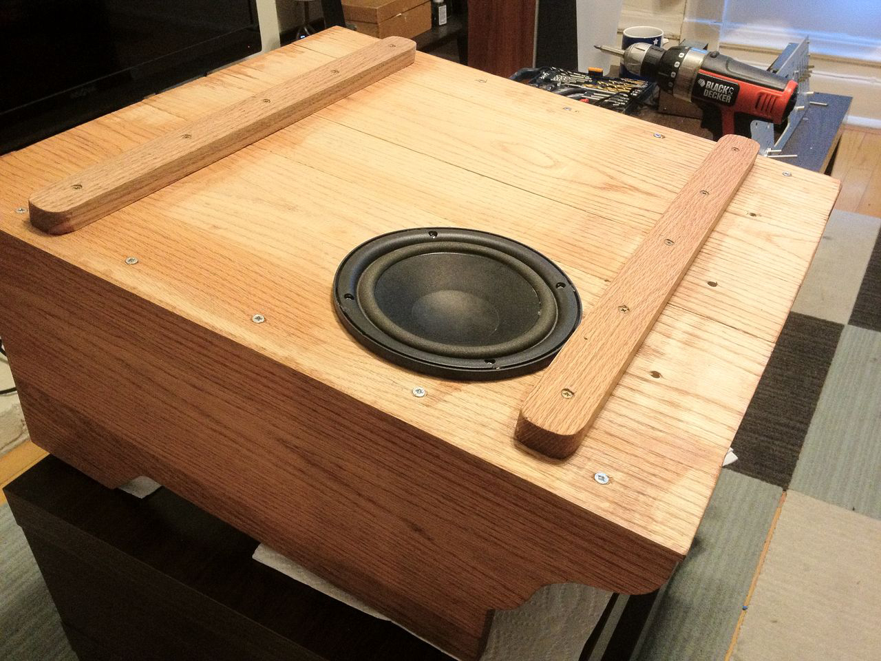
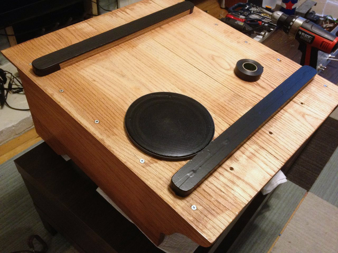
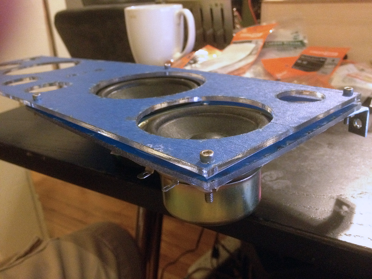
For the speaker mounting, I didn't want tons of screw holes visible on the faceplate. I designed a double-pane system that lets the speakers mount to a hidden inner plate, which is then mounted to the front using only 4 screws instead of 8+.
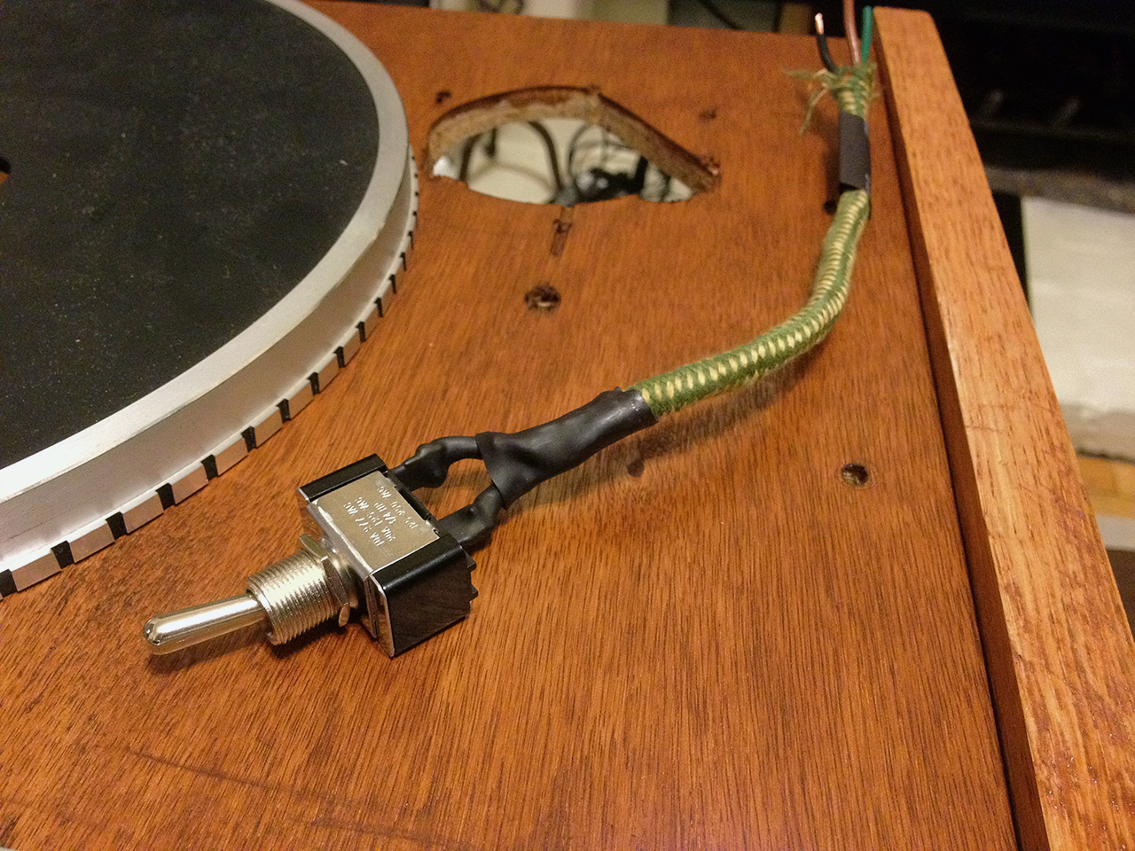
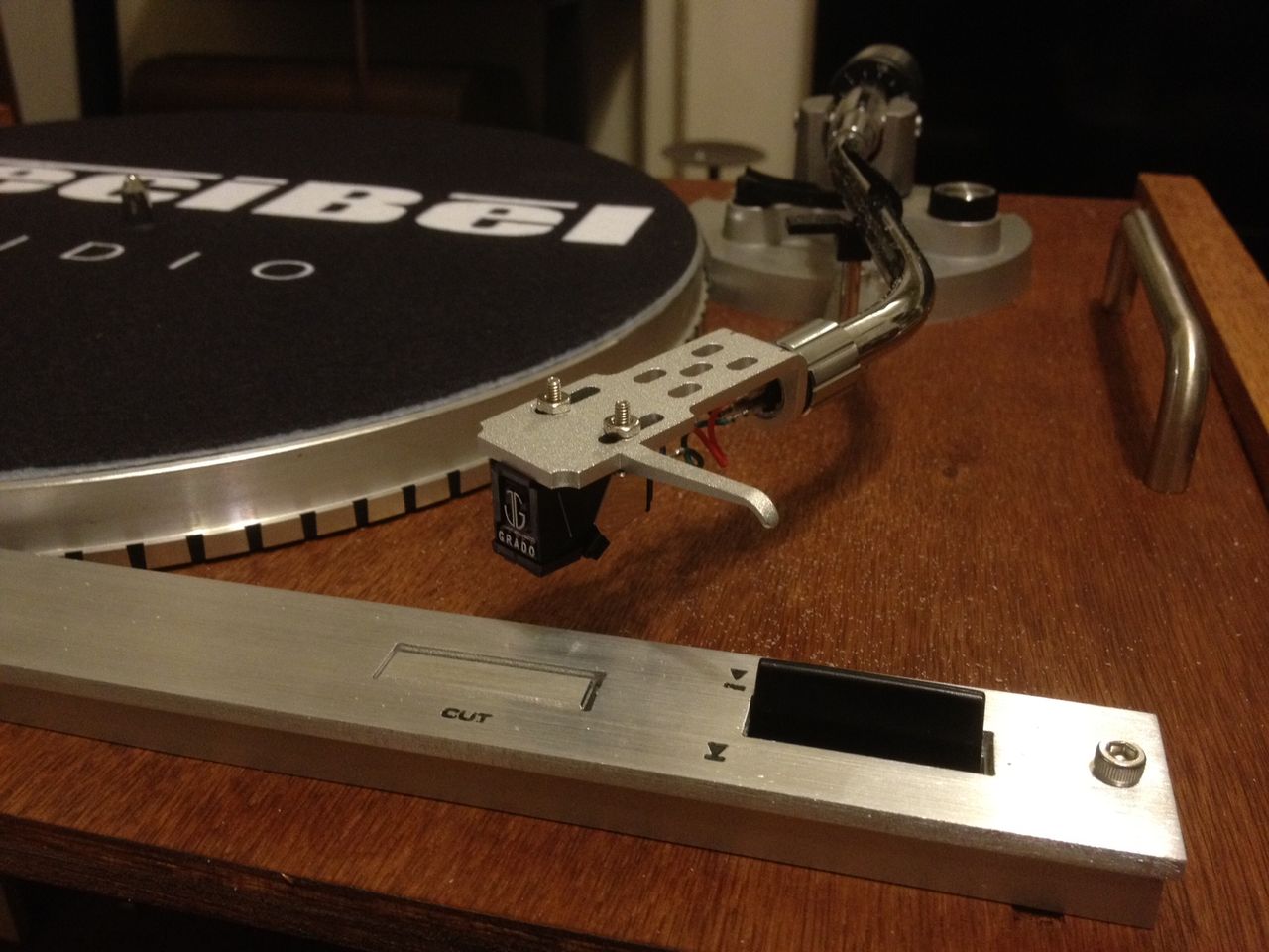
For the record player, I'm using the parts from this vintage Yamaha YP-D4. I specifically seeked out this model because I love the way the tone arm looks. I picked this one up on Craigslist for $50, as it is in pretty rough cosmetic shape. Mechanically though, all it needed was a cartridge + head-shell and it sounds amazing.
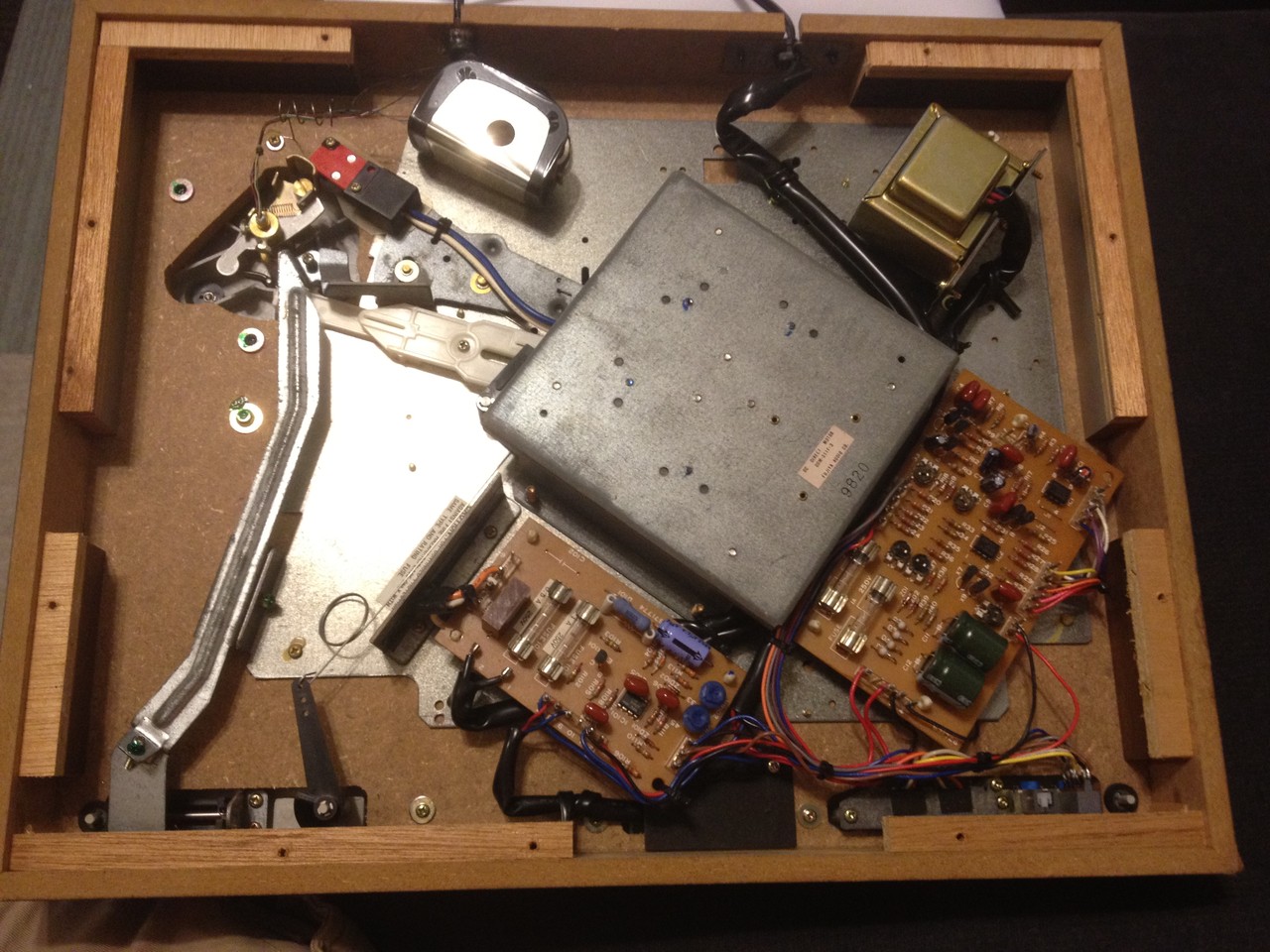
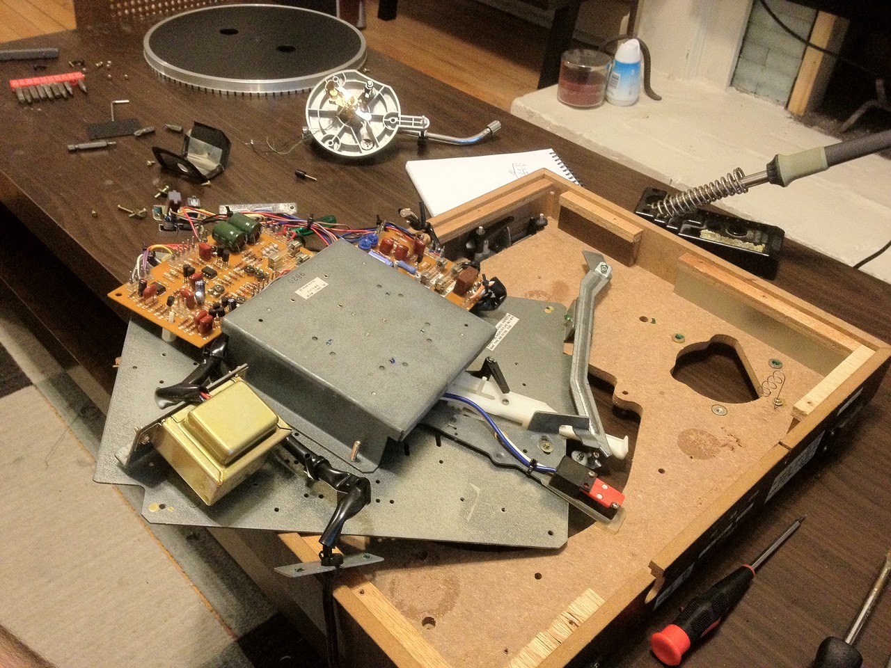
It turned out to bit a bit of a chore taking this thing apart. Yamaha used about 20 screws from both the top and bottom, AND glue. I hate glue.
The inside. Really neat vintage electronics.
Finally the guts separate from the shell.
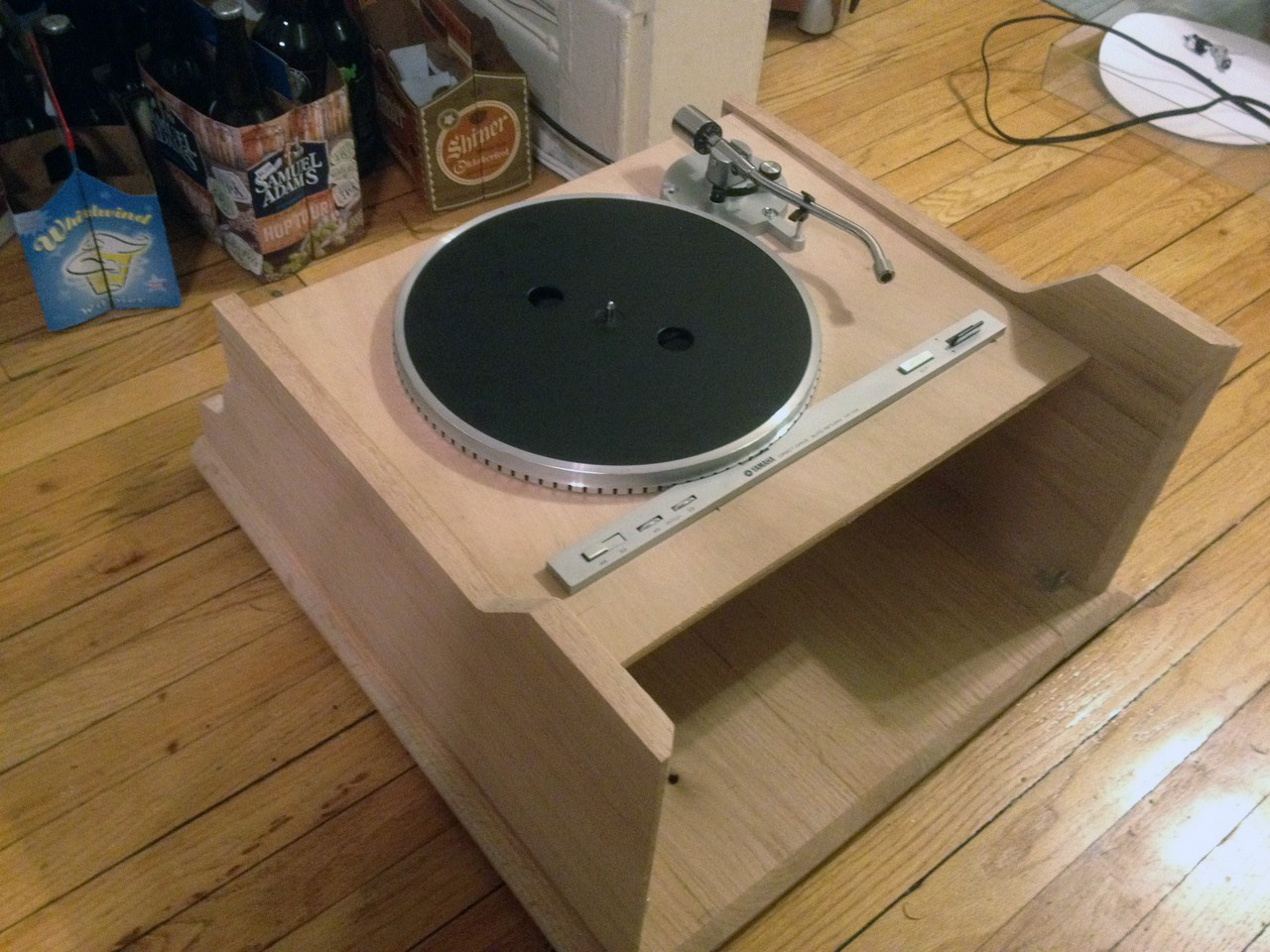
Now, for the new case, I just traced the cut-outs and mounting holes from the original directly onto the new ply.
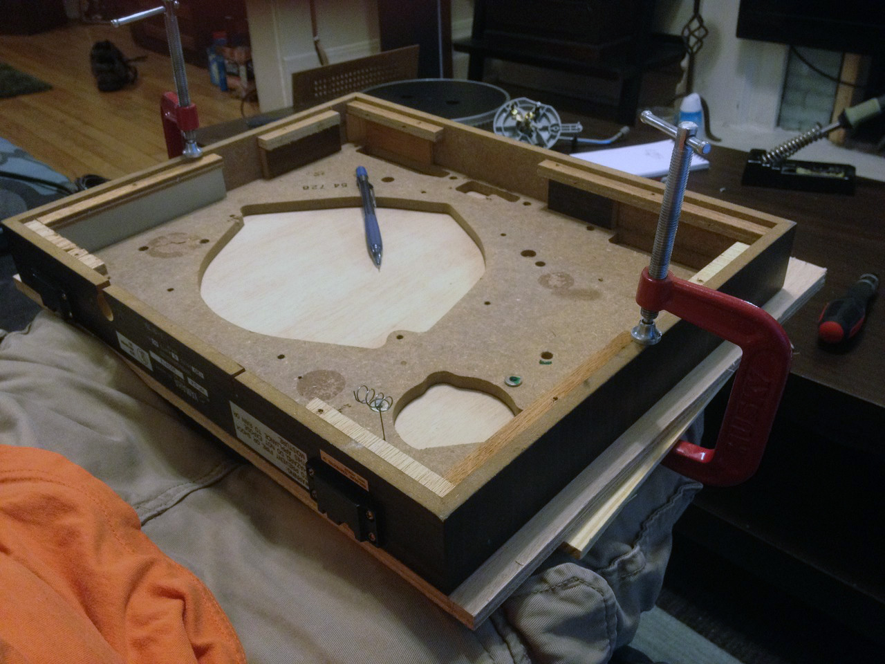
Cut it out using a jig-saw and hand drill, and here's the new base:

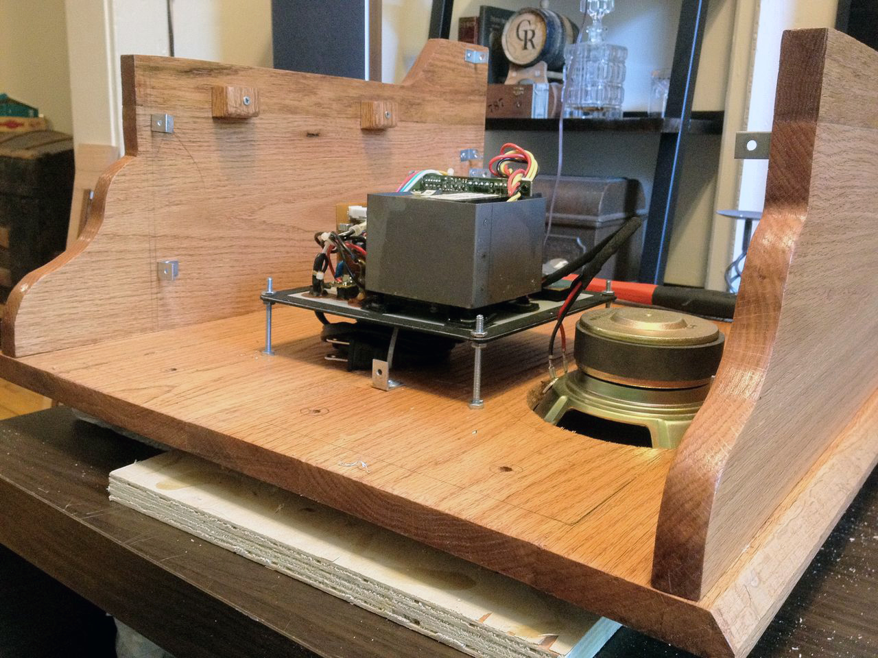
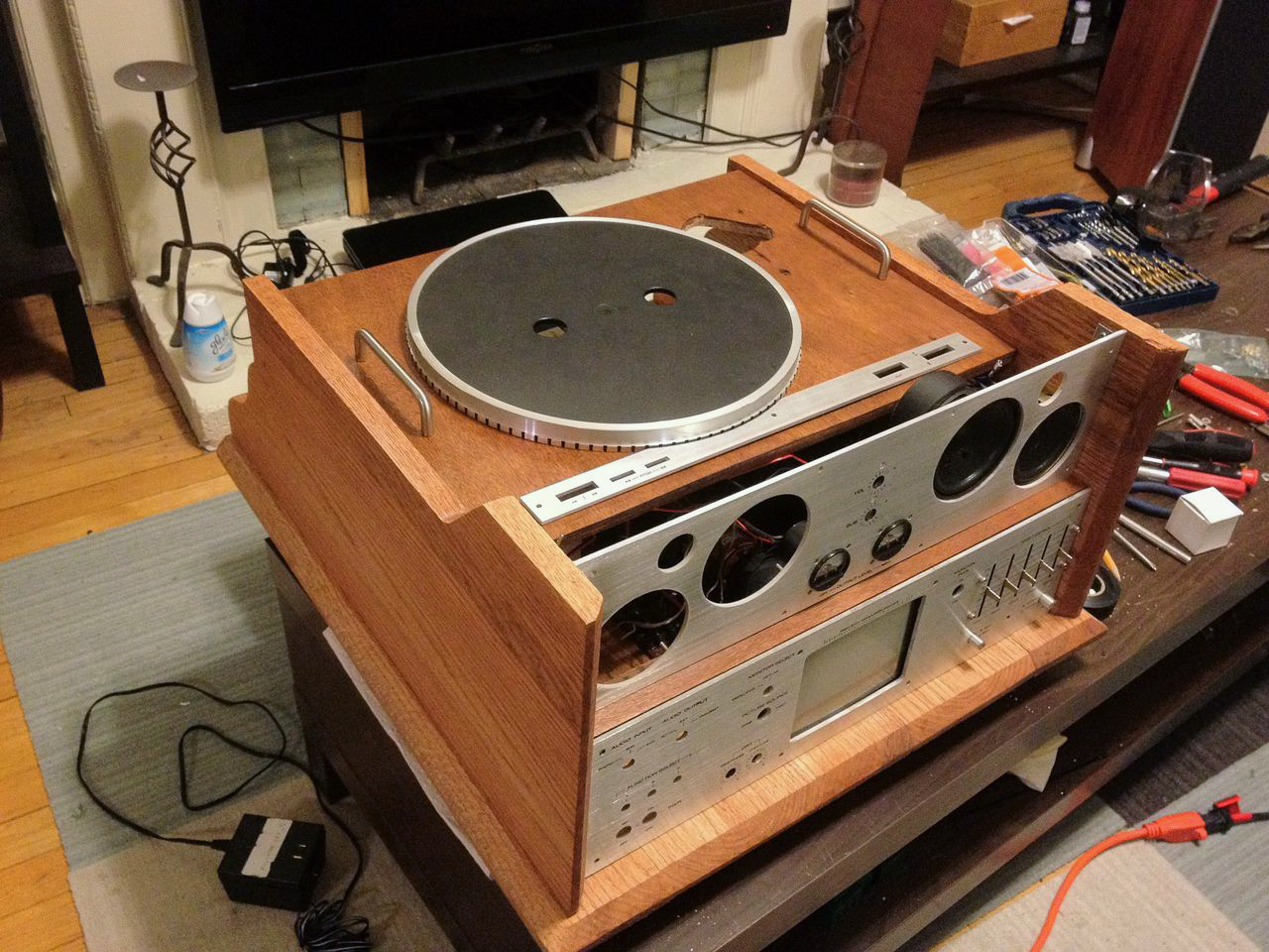
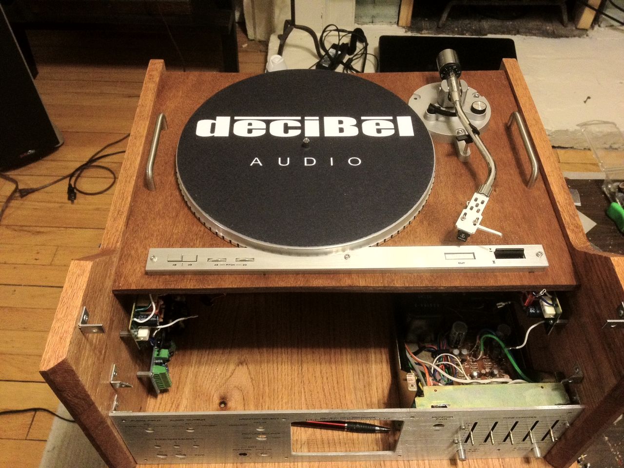
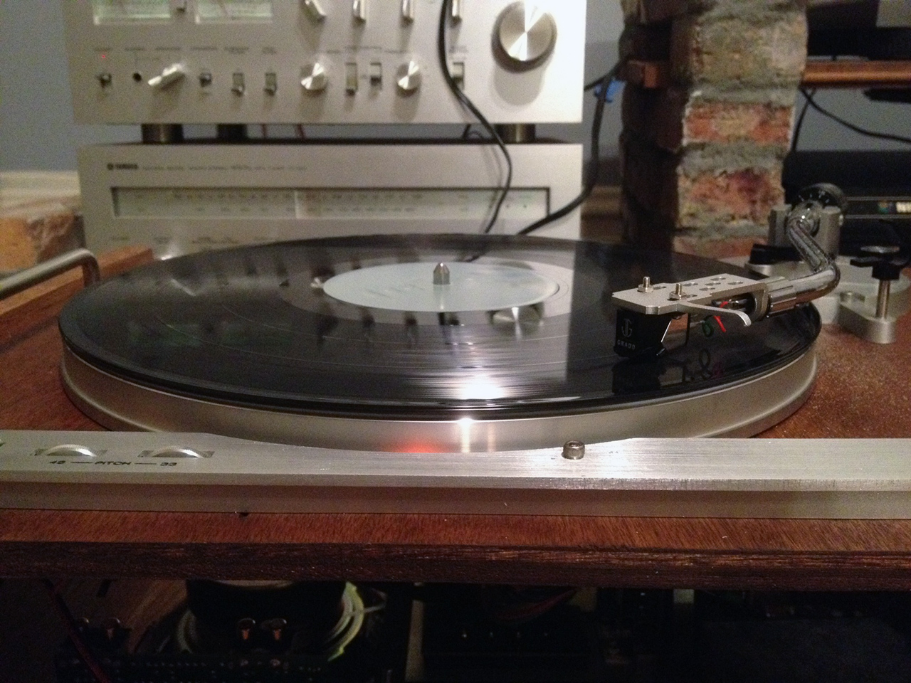
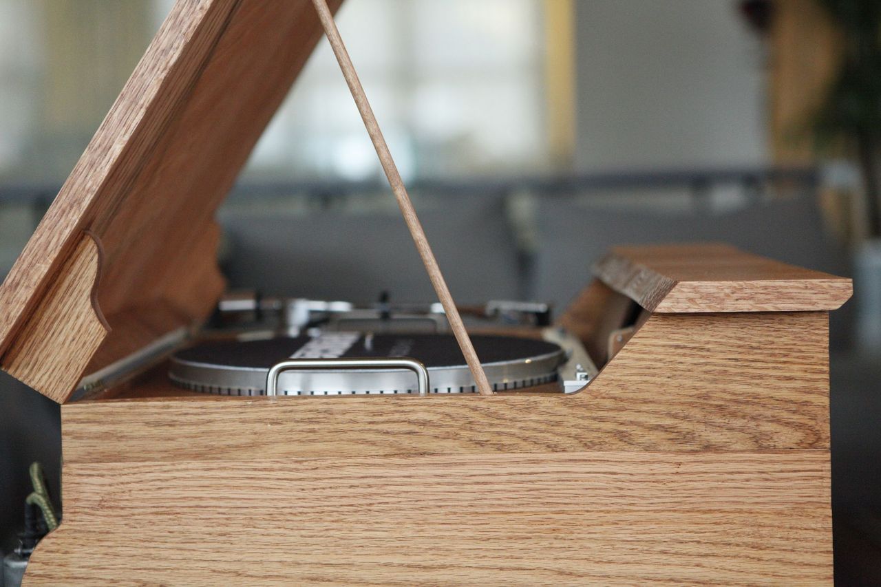
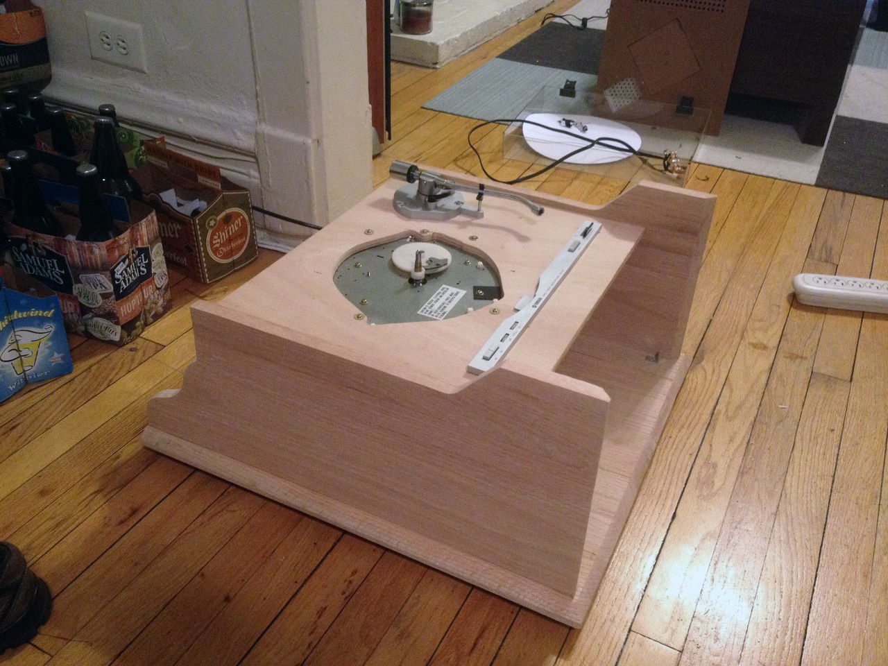
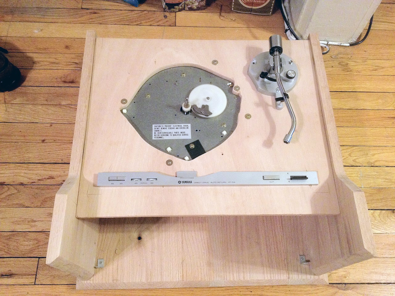
All I have to do is re-assmble all the parts into the new case. Everything should work exactly as did before, including the mechanical tone-arm controls that rely on springs & levers.
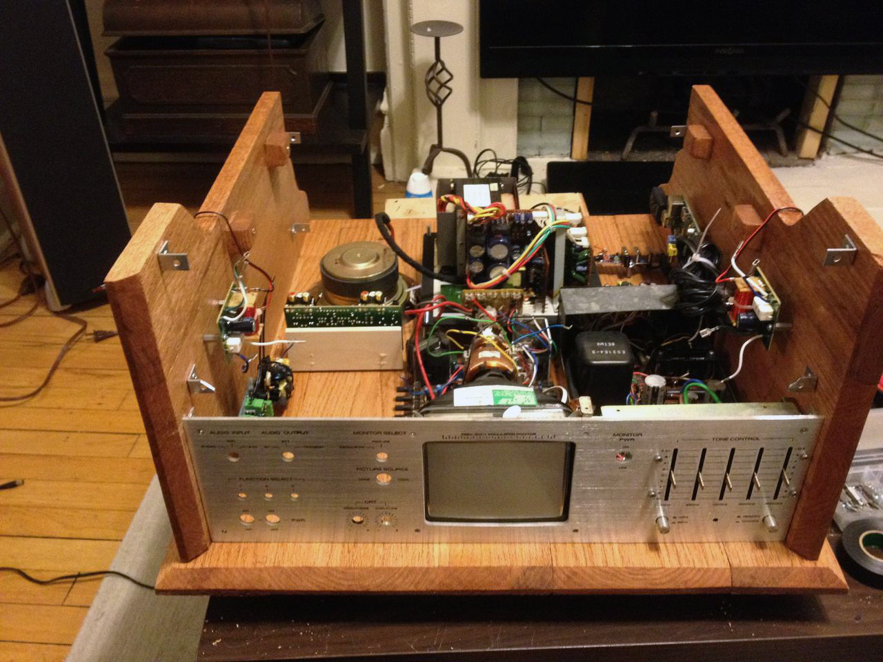
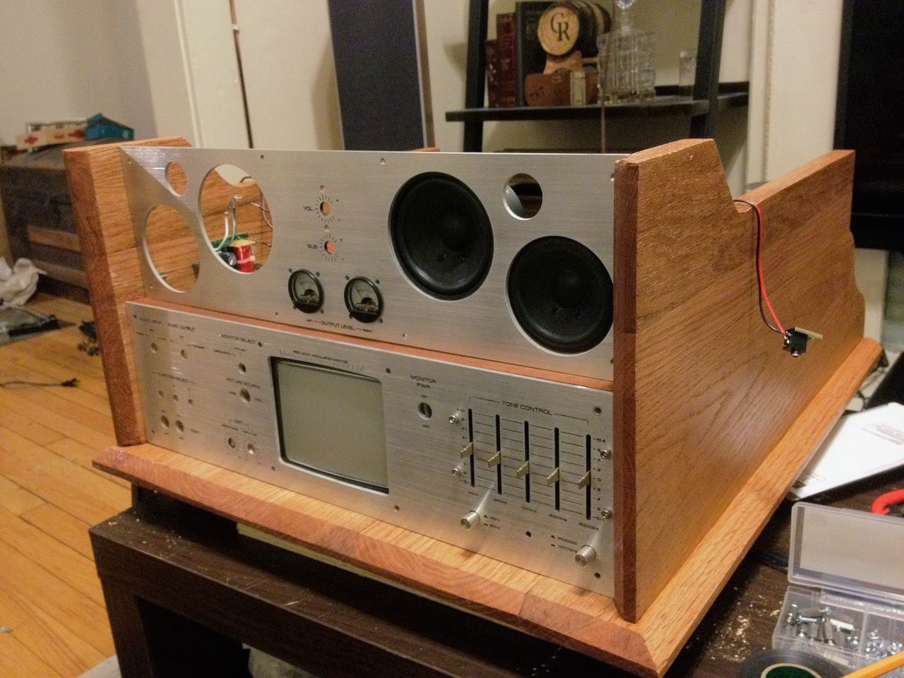
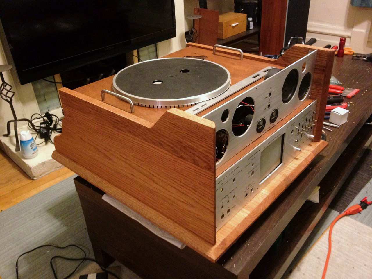
Wow, now it's finally starting to look like something:
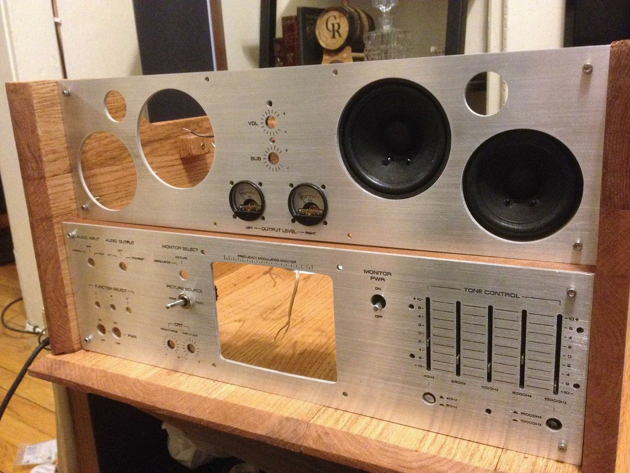
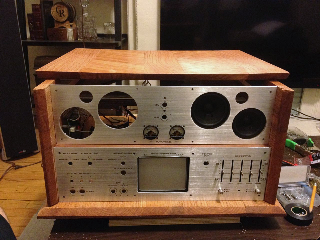
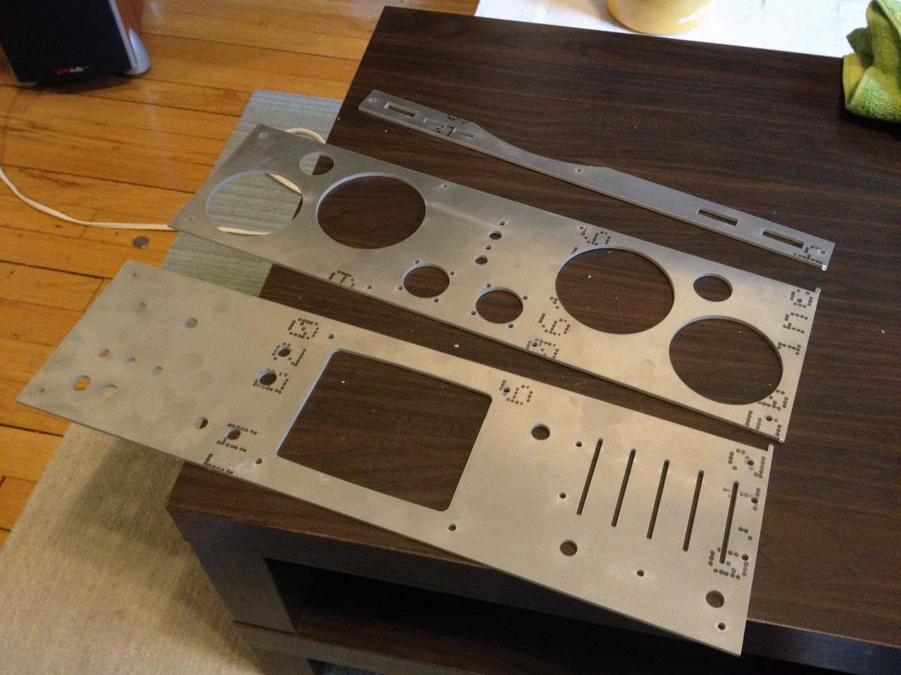
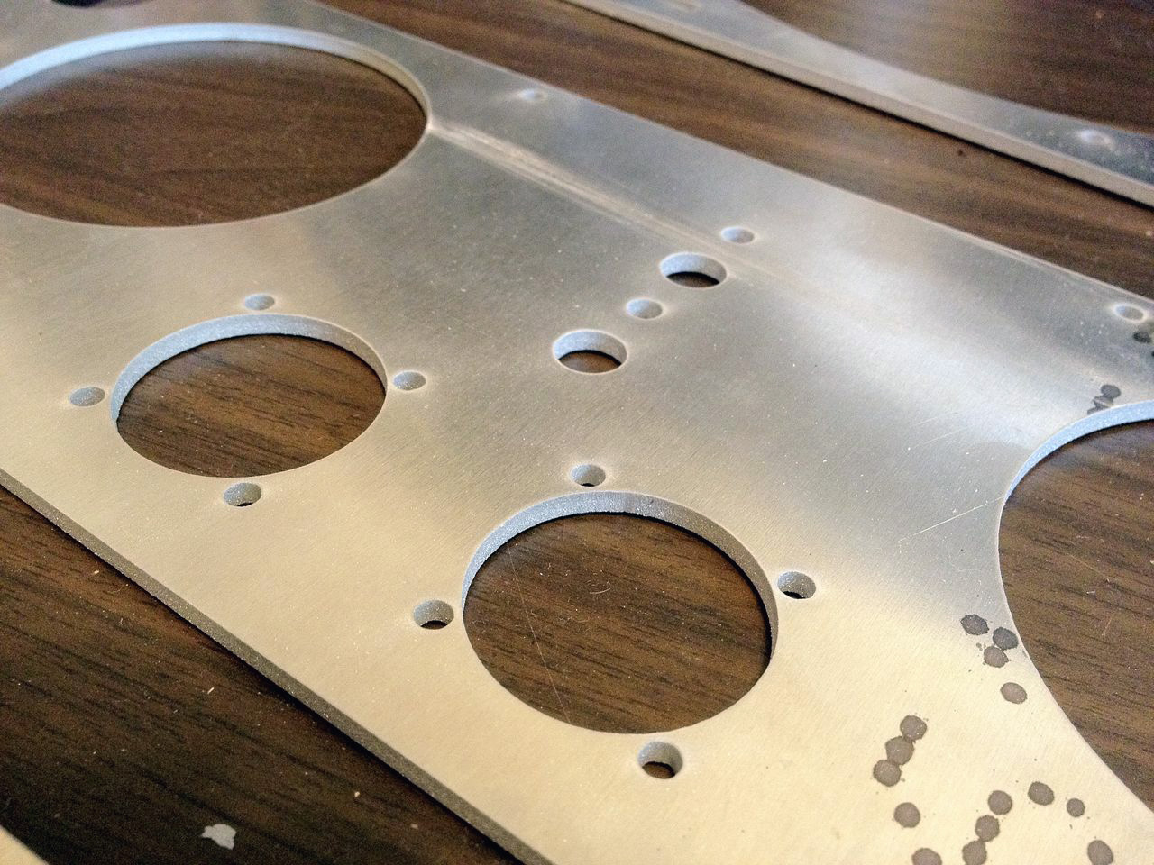
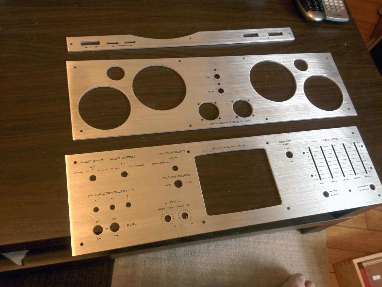
After making some alignment and layout tweaks to my faceplate design, I sent away for it to be cut out of aluminum at BigBlueSaw.com. I'm very pleased with the result:
And now for the most challenging part of the project yet...
Many vintage stereos feature etched faceplates. That is, the typography is actually engraved in the surface. It creates a unique look and spirit that I really wanted to embody here. At first it seemed like a crazy ambitious goal way out of my reach. However after discovering this thread about how to create your own custom etched metal panels, I realized it might just be in scope after-all. I researched various DIY solutions and landed on what's known as a "Saline Sulphate" etch. It's a relatively safe and simple (compared to the more acidic and electrically charged alternatives) etching process that uses a common chemical "copper sulphate" and salt solution to effectively etch aluminum.
Here's a brief rundown on the process:
Tools: Copper sulphate crystals (they're blue), salt, and all the blah-blah-safety stuff-blah-blah.
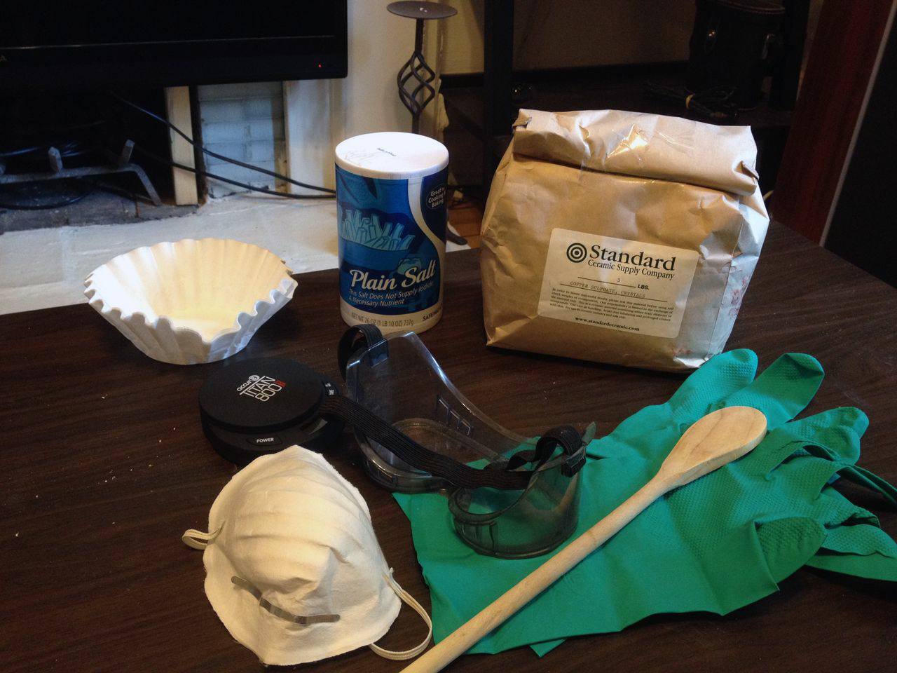

I learned the specifics of the saline sulphate etching method through this site that lists a specific recipe. I scaled it up a bit, using a solution of:
+150g copper sulphate
+150g salt
+1,800ml hot water
First you design the graphics in Illustrator or whatever you please.
Invert the colors and print it out 1:1 on glossy photo paper for laser printers. I found that the thinner, cheaper stuff works much better than the heavier weight you sometimes find in photo paper. Note that a laser printer is crucial; inkjet won't work.
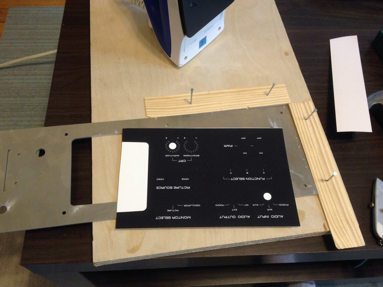
The theory here is that you print the negative (and horizontal mirror) of the design on a laser printer, which uses a liquid polymer toner that's fused through heat. Using an iron, you can transfer your printed design onto the metal surface.
I found that having my metal plate pre-cut with holes was a huge problem for the transfer of design from paper to plate. I ended up having to trim away all the excess, making sure no paper would hang over the edges. The overhangs would cause bubbling when transferring onto the plate, leading to major defects in the integrity of the graphics.
Ironed onto the back of the metal plate:
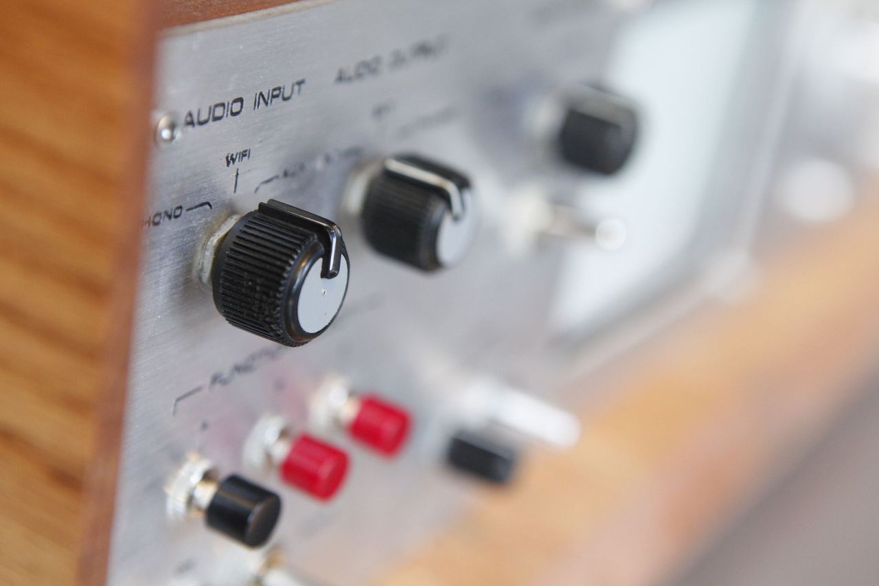
This particular piece is a new cover for the record player control pod.
After you iron on design onto the board, you mask off all the edges and extra space around the lettering. Any exposed metal will be eroded, so the idea is that you want to cover everything except for the parts you want to be etched.
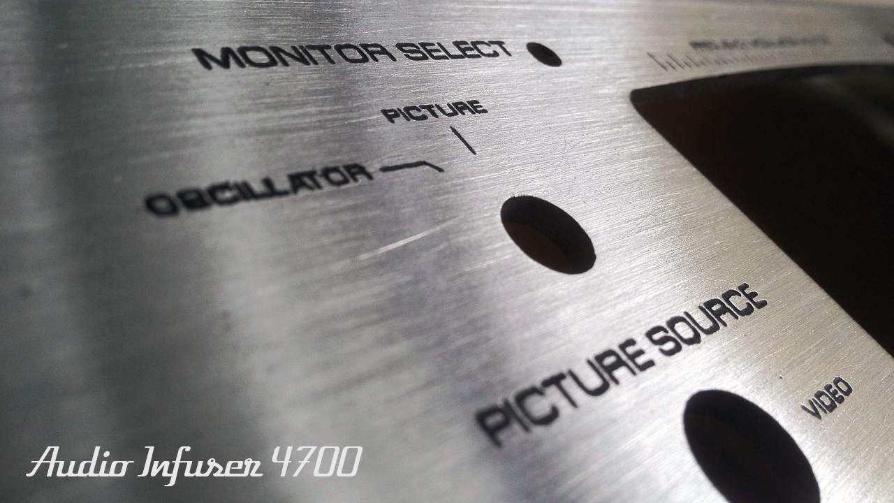
And here it is after etching and removing the tape. This was about 10 minutes spent soaking in the saline sulphate solution (copper sulphate + salt). The letters got a little too fat, so for the other pieces I ended up stopping the etch at 7 minutes which gave a much more refined result.
If you want to see an early test (my first etch test), you can see how badly it turned it compared to this one. The background plate here etched for 30 minutes, which is what I read the norm was. Guess my mixture is a little stronger than that or something....
To get the black lettering effect I wanted, I filled in all the graphics with a generous amount of black enamel paint. It looks ugly here, but you have to imagine how it will look once the surface is sanded down. Everything will be returned to bare metal except for the etched bits.
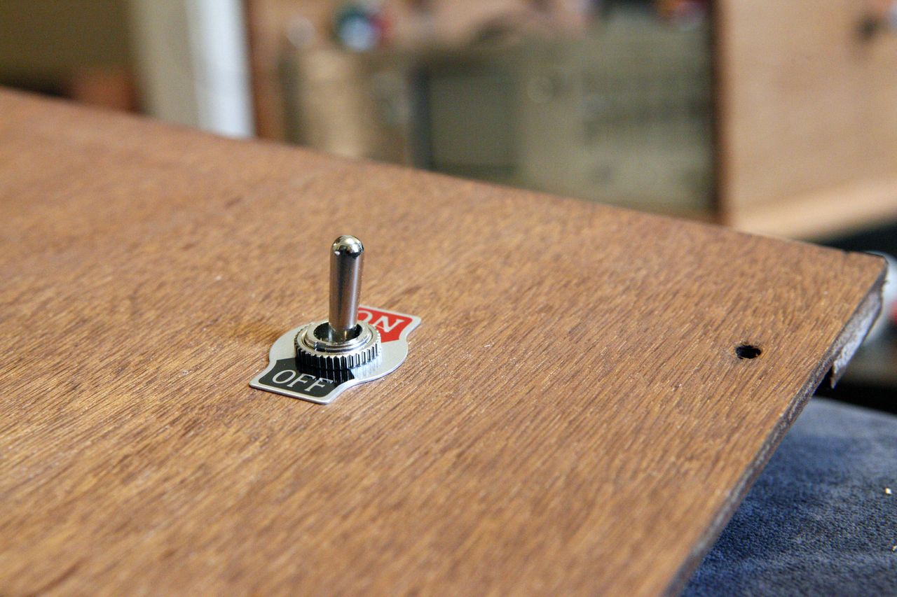
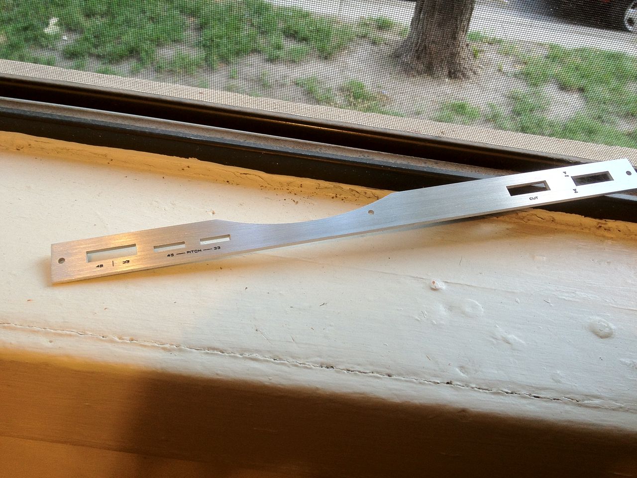
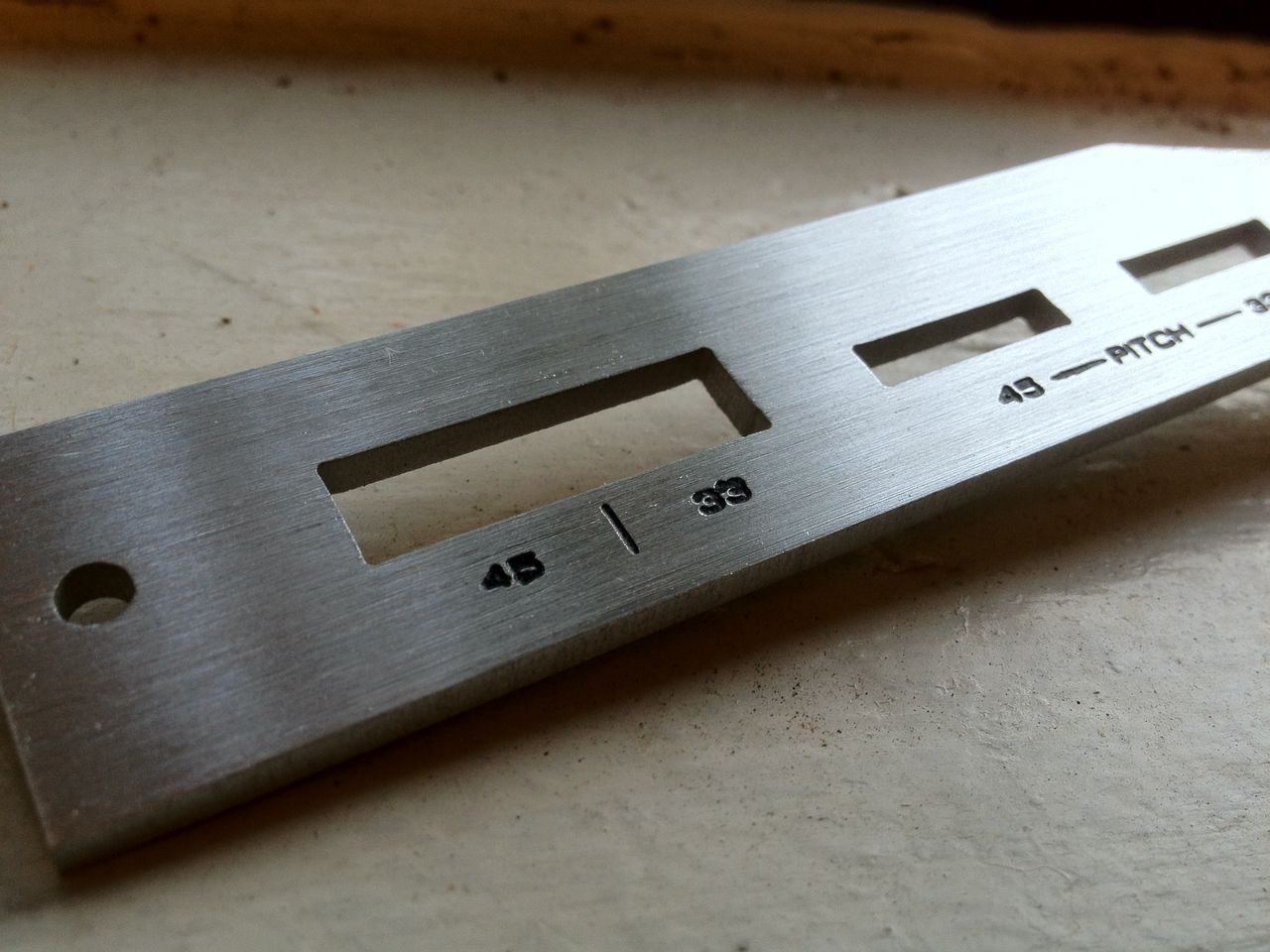
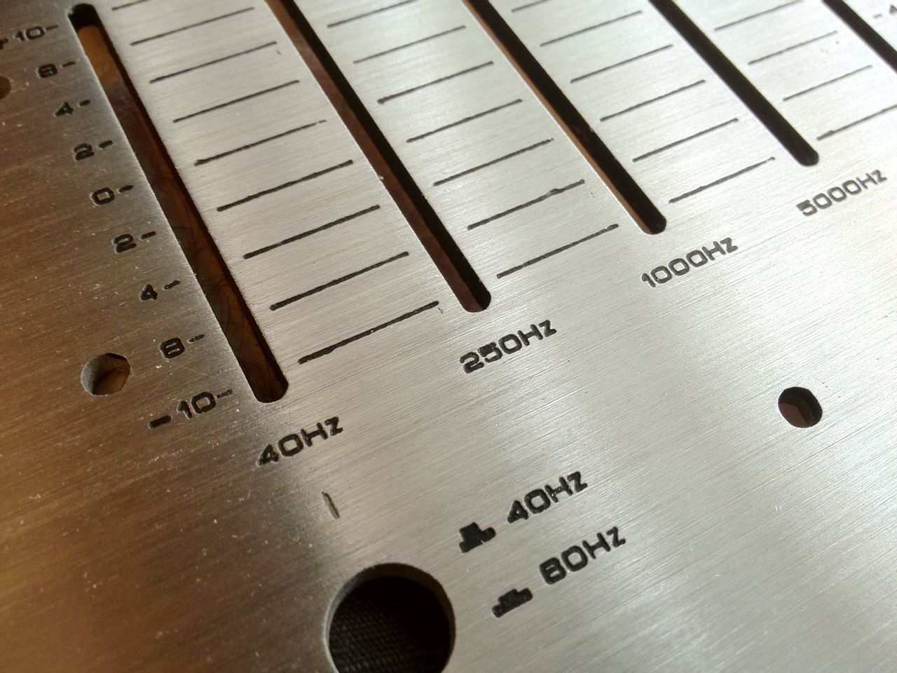
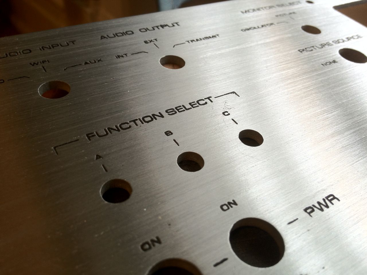
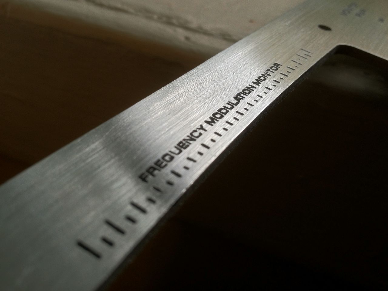
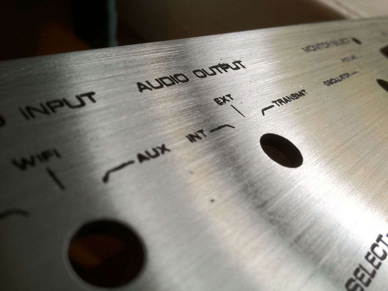
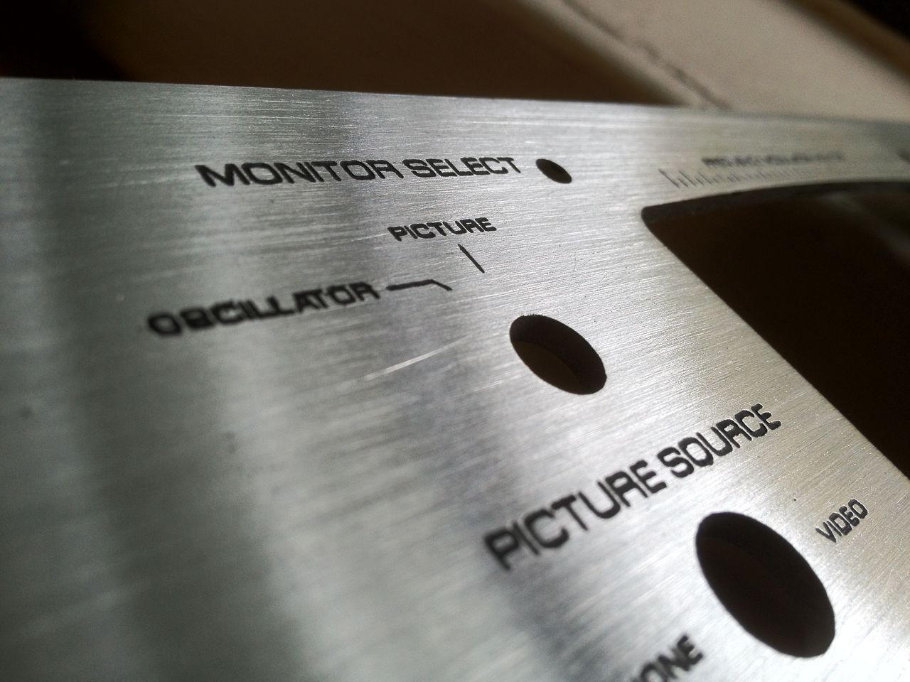
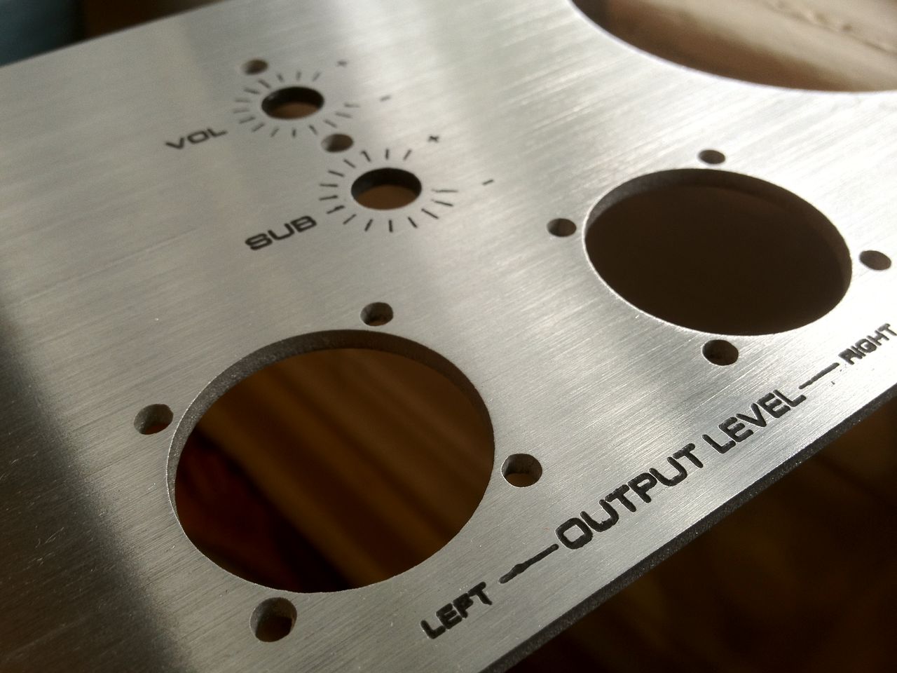
Sand down the surface and you get a rather nice looking etched panel:
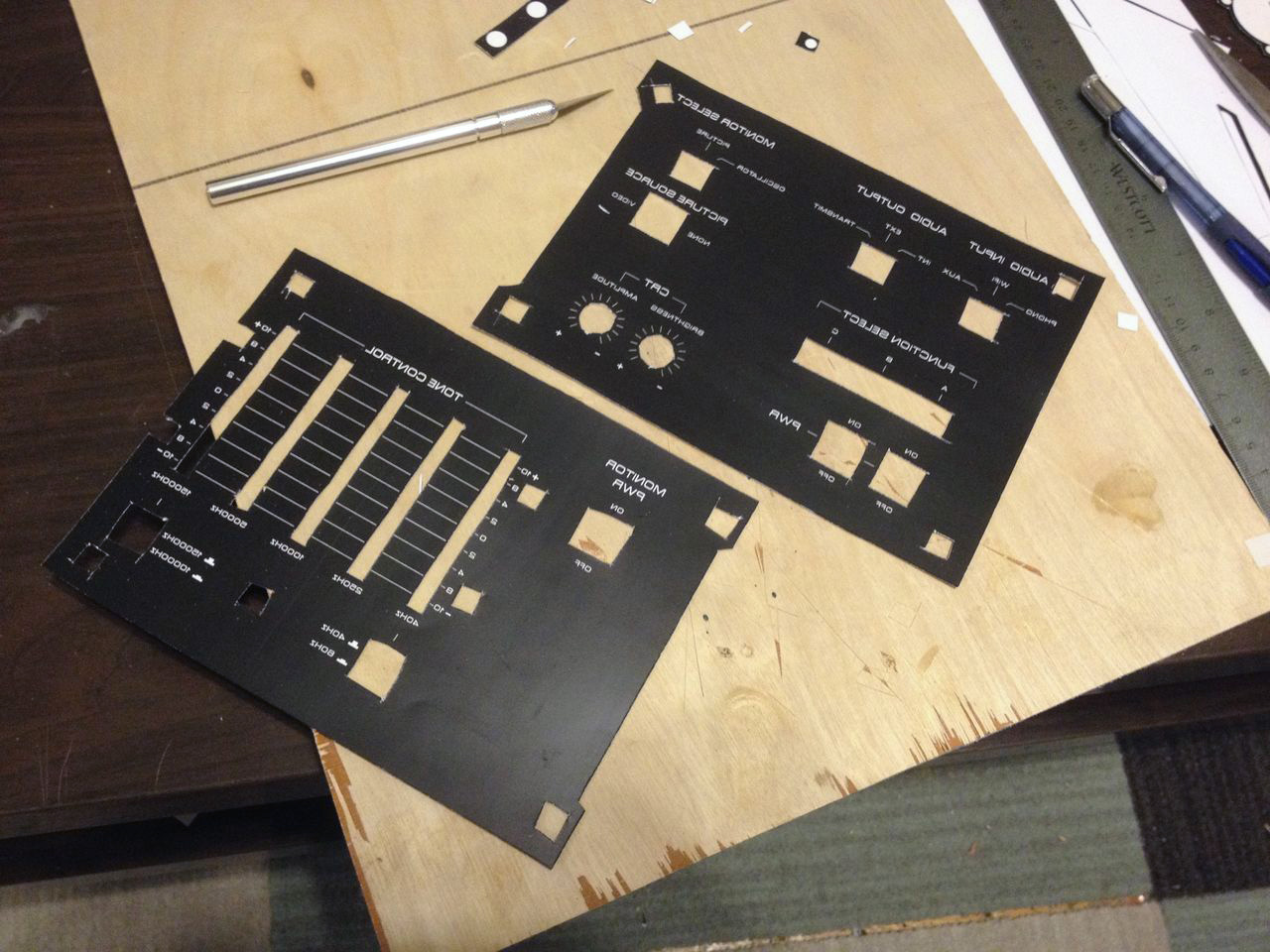
Going back a bit, here's some shots of the other metal pieces and other parts of the process:
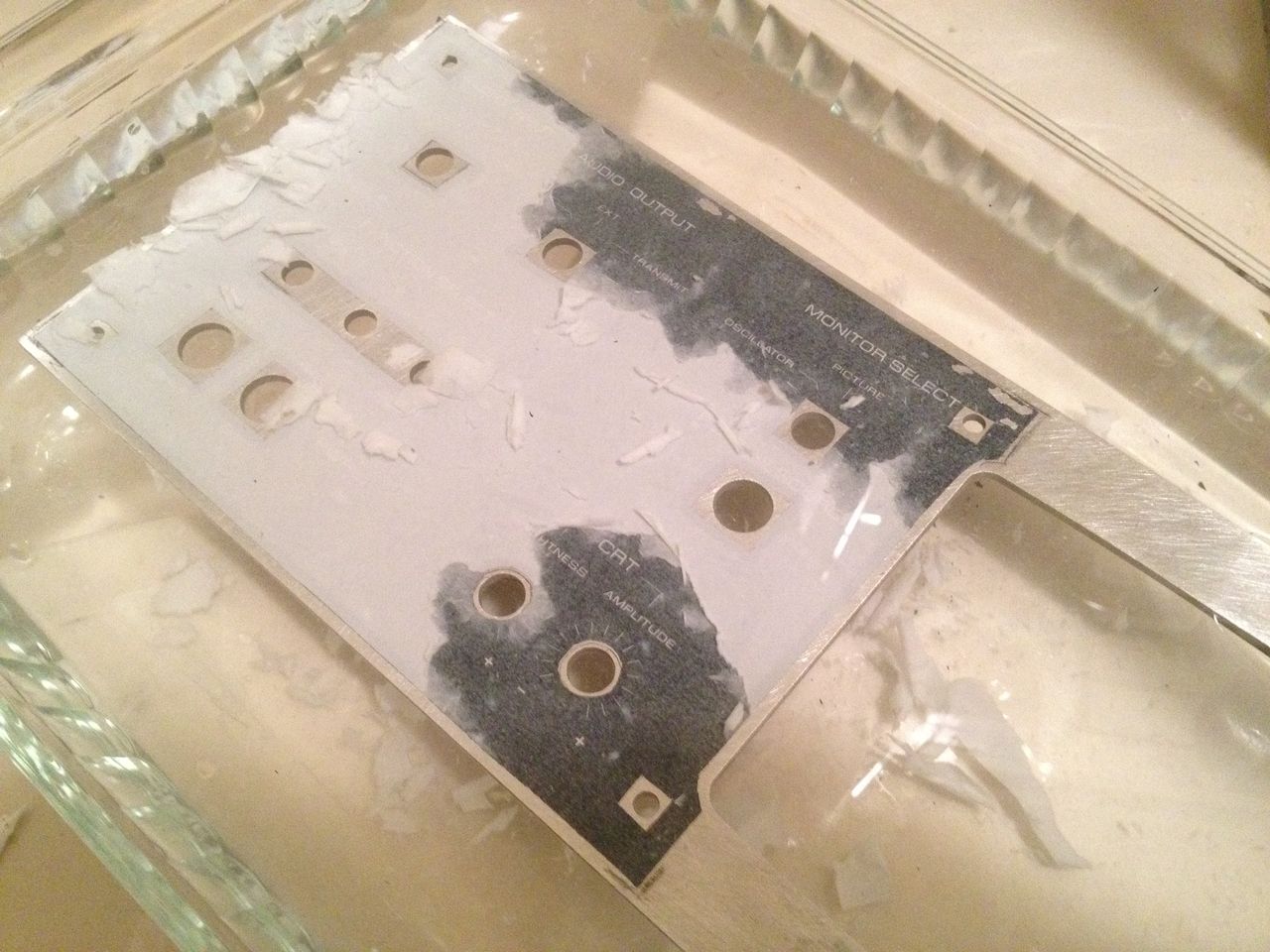
After you iron the printed graphic toner onto the plate, it gets dunked in a bath of cold water. The paper soaks, allowing you to peel it away leaving only the toner adhered to the plate.
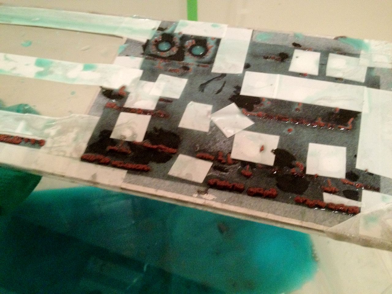
And here it is in the saline sulphate etching solution. Bubbles rise from the exposed bits and it generates a brown, rust-like by product:
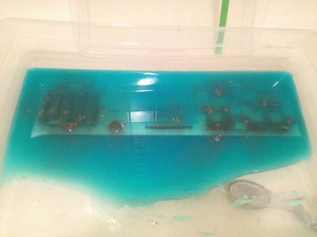
Mounds of the byproduct protrude directly from the etching graphics:
Wipe it down, peel off the tape, paint the graphics black, and sand the surface down and you get this:
I was pretty happy with how these came out. It was my first time experimenting with etching, and know it won't be my last. It did take a bit of trial and error though.
I achieved the brushed aluminum finish using 60 grit sand paper, a sanding block, and a jig to keep the sanding motion perfectly parallel with the plate. It could probably use a bit deeper of a sanding, as there are still a few stray scratches that really stand out in certain lighting.
NEXT STEPS:
01) Finish building wood case, and stain it.
02) Once case is stained, install faceplates and begin mounting components.
03) Fabricate internal brackets and standoffs for all the various components that need to be secured
04) Wire everything together.
----------------------------------
(Original build log below)
----------------------------------
This has been in design and production for about 4 months, on and off, but i'm finally now with enough progress and momentum to warrant a proper work log.
It's a stereo/boombox that streams music over WiFi and also plays vinyl records. It has a built in music visualizer, an analog graphic EQ, and a few other tricks up it's sleeve. It's meant to be an all-in-one audio playing device with dynamic options for any music playing scenario. Here's a breakdown of it's features:
WHAT IT DOES:
01) Using a Raspberry Pi, streams music over WiFi from your mobile device (using ShairPort, functions like Apple AirPlay)
02) Has a built-in turntable to play vinyl records (parts adapted from a vintage Yamaha YP-D4)
03) Has four built in mid-range speakers, two tweeters, and one subwoofer (parts adapted from Klipsche ProMedia 2.1, with two additional speakers)
04) Has an analog graphic equalizer with 7 effective frequency bands (parts adapted from JVC SEA-10 vintage EQ)
05) Has a 5" CRT monitor that functions as an analog music visualizer, behaving similar to an oscilloscope
06) Can switch output from internal speakers to external device (via RCA cables)
07) Can also output wirelessly, transmitting over a medium which is still TBD. Will be either over WiFi using the Raspberry Pi, or to a specific FM band using a mini FM transmitter.
08) Can take auxiliary input from any device via 1/8" audio jack.
09) The Raspberry Pi can be switched into arcade mode, using AdvanceMAME emulator to play classic arcade games on the 5" CRT. Current functional games include PacMan, Asteroids, and Space Invaders using a custom USB controller pad.
The visual design is very heavily inspired by vintage HiFi equipment. Its housed in a wooden case, and has a brushed aluminum faceplate with heavy-duty switches and knobs.
Here's my 3D mockup of the physical design:
I first began by collecting items i'd need.
Here's a first test using the Klipsche ProMedia stereo set, the JVC EQ, and the 5" CRT:
I knew I wanted a visualizer for this project. I wasn't able to find any good looking software based visualizers that functioned on Raspian Wheezy (the default Raspberry Pi OS; I'm a Linux newb), but I happened upon this Instructables tutorial on how to turn a CRT monitor into an analog oscilloscope: [link]
Surprisingly, all it takes is a couple of wire snips. CRT monitors have two sets of wires that run to the tube: vertical coils and horizontal coils. The combination of the two produces the X/Y grid of pixels you see. To turn a cathode tube into a crude oscilloscope, all you do is connect the horizontal coil inputs to a generic speaker wire output. It really is as simple as that. The audio sent through the speaker wire will drive the horizonal coils to jump around depending on the frequency and volume, giving you a really mesmerizing visualization of your music.
Here's a video of the CRT oscilloscope visualizer in action: [photo will link out to vimeo video]
I also recorded a video showing waveforms as I play with an analog synthesizer (actually it's just the Moog Google Doodle): [vimeo video link]. In this video you also see the demonstration of how varying volumes effect the amplitude. For my stereo, I've fixed a potometer to the speaker wire input, offering an adjustment to the amplitude without compromising the volume output. This is useful because I found it can often be visually desirable to reduce the wave amplitude (i.e. spazzyness) in high volume scenarios.
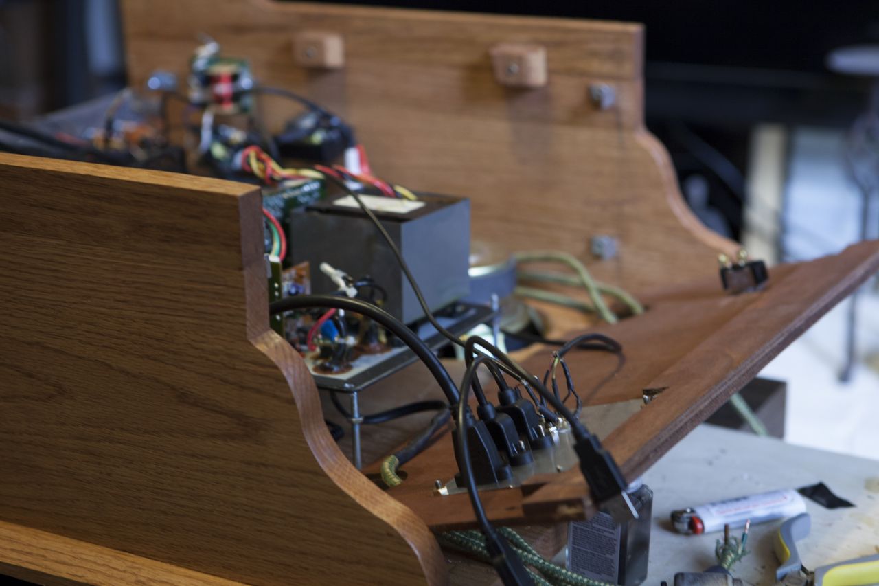
A little bit more work and I have a working prototype of all the electronic components:
Here's a closeup of the VU meters, purchased on ebay from Japan! There will be one for LEFT and one for RIGHT channels
Now it's time to build the case. Like I said, it will be heavily inspired by vintage HiFi equipment like this Marantz amplifier, for example.
I live in the city of Chicago, so I'm limited to what I can accomplish in my 1BR apartment, with no outdoor space. My kitchen and my living room are my work spaces:
Never the less, I use hand saws, hand files, a jig-saw, Dremel, and cordless drill, and old fashion engineering to make it happen little by little:
For the top, which will be a hinged lid covering the record player, I wanted to give it a slight decorative touch. I found some Red Oak with a cool marble pattern in it, so I decided to use that as angled slice insets:
Here it is all glued together:
A mock-up of the case coming together: (please refer back to the [3D design image] for imaginative extrapolation purposes)
For the front, I really wanted a nice brushed aluminum face-plate to house all the switches and stuff. Since I don't have access to a CNC or other mill equipment, I found this awesome internet resource BigBlueSaw.com which will take your CAD drawing (or Illustrator or other vector image) and cut it out of various materials for you including acrylic, aluminum, steel, wood, and leather.
I started by designing a faceplate in AutoCAD:
I first had Big Blue Saw cut me a prototype out of acrylic so I could test fit my size and mounting holes (which I laid out using a ruler, my eye, and best judgement)
For the speaker mounting, I didn't want tons of screw holes visible on the faceplate. I designed a double-pane system that lets the speakers mount to a hidden inner plate, which is then mounted to the front using only 4 screws instead of 8+.
For the record player, I'm using the parts from this vintage Yamaha YP-D4. I specifically seeked out this model because I love the way the tone arm looks. I picked this one up on Craigslist for $50, as it is in pretty rough cosmetic shape. Mechanically though, all it needed was a cartridge + head-shell and it sounds amazing.
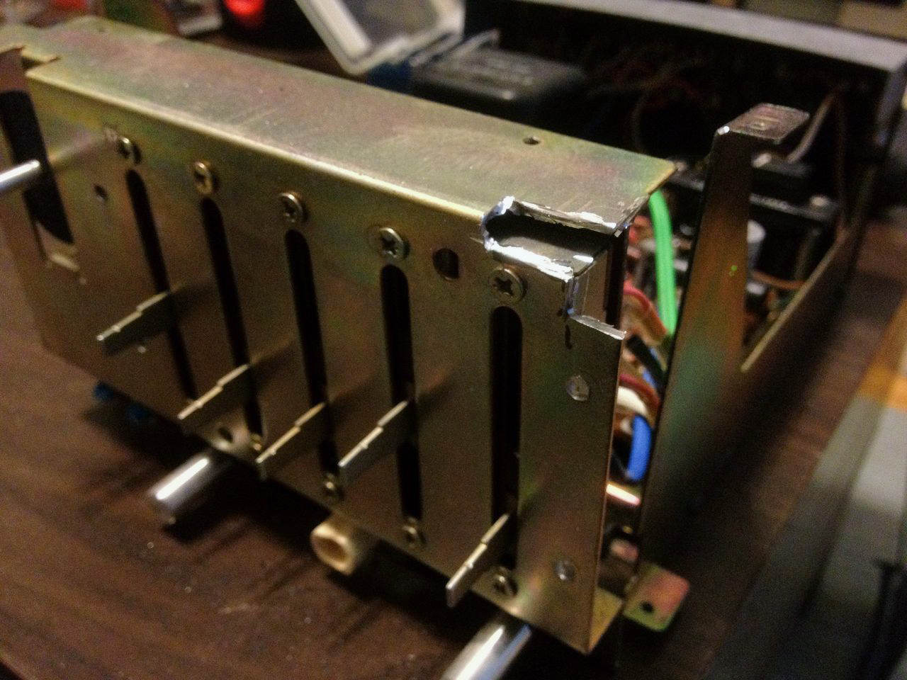
It turned out to bit a bit of a chore taking this thing apart. Yamaha used about 20 screws from both the top and bottom, AND glue. I hate glue.
The inside. Really neat vintage electronics.
Finally the guts separate from the shell.
Now, for the new case, I just traced the cut-outs and mounting holes from the original directly onto the new ply.
Cut it out using a jig-saw and hand drill, and here's the new base:
All I have to do is re-assmble all the parts into the new case. Everything should work exactly as did before, including the mechanical tone-arm controls that rely on springs & levers.
Wow, now it's finally starting to look like something:
After making some alignment and layout tweaks to my faceplate design, I sent away for it to be cut out of aluminum at BigBlueSaw.com. I'm very pleased with the result:
And now for the most challenging part of the project yet...
Many vintage stereos feature etched faceplates. That is, the typography is actually engraved in the surface. It creates a unique look and spirit that I really wanted to embody here. At first it seemed like a crazy ambitious goal way out of my reach. However after discovering this thread about how to create your own custom etched metal panels, I realized it might just be in scope after-all. I researched various DIY solutions and landed on what's known as a "Saline Sulphate" etch. It's a relatively safe and simple (compared to the more acidic and electrically charged alternatives) etching process that uses a common chemical "copper sulphate" and salt solution to effectively etch aluminum.
Here's a brief rundown on the process:
Tools: Copper sulphate crystals (they're blue), salt, and all the blah-blah-safety stuff-blah-blah.
I learned the specifics of the saline sulphate etching method through this site that lists a specific recipe. I scaled it up a bit, using a solution of:
+150g copper sulphate
+150g salt
+1,800ml hot water
First you design the graphics in Illustrator or whatever you please.
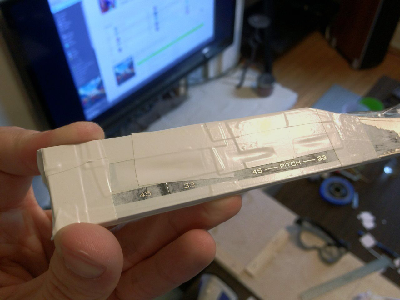
Invert the colors and print it out 1:1 on glossy photo paper for laser printers. I found that the thinner, cheaper stuff works much better than the heavier weight you sometimes find in photo paper. Note that a laser printer is crucial; inkjet won't work.
The theory here is that you print the negative (and horizontal mirror) of the design on a laser printer, which uses a liquid polymer toner that's fused through heat. Using an iron, you can transfer your printed design onto the metal surface.
I found that having my metal plate pre-cut with holes was a huge problem for the transfer of design from paper to plate. I ended up having to trim away all the excess, making sure no paper would hang over the edges. The overhangs would cause bubbling when transferring onto the plate, leading to major defects in the integrity of the graphics.
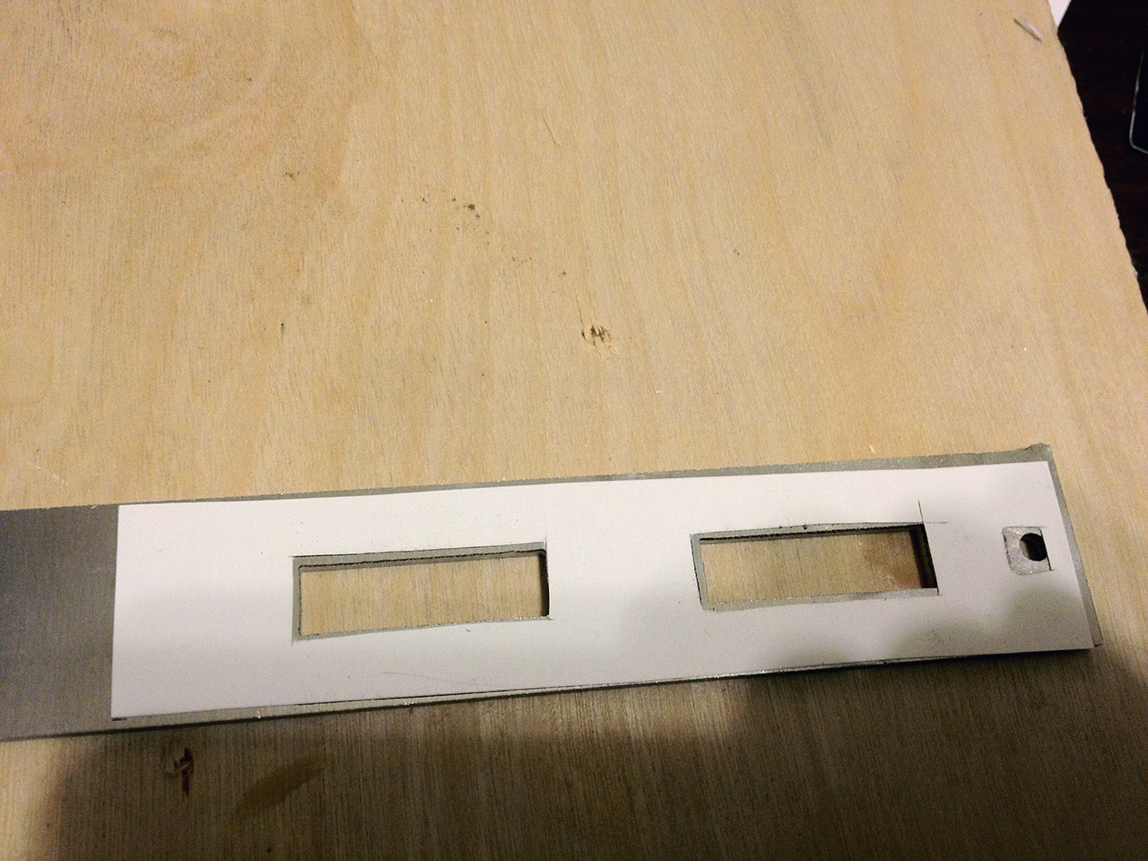
Ironed onto the back of the metal plate:
This particular piece is a new cover for the record player control pod.
After you iron on design onto the board, you mask off all the edges and extra space around the lettering. Any exposed metal will be eroded, so the idea is that you want to cover everything except for the parts you want to be etched.
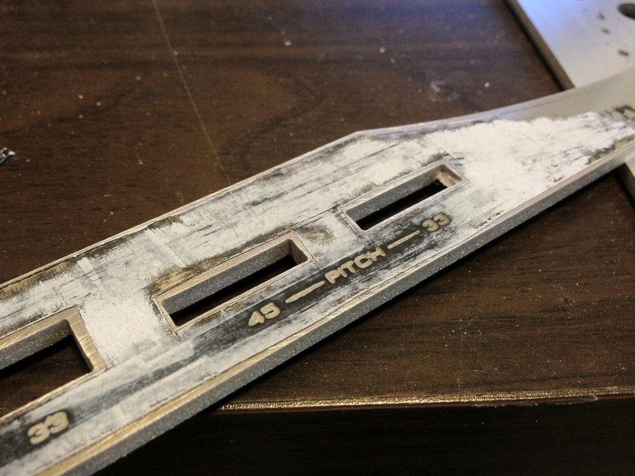
And here it is after etching and removing the tape. This was about 10 minutes spent soaking in the saline sulphate solution (copper sulphate + salt). The letters got a little too fat, so for the other pieces I ended up stopping the etch at 7 minutes which gave a much more refined result.
If you want to see an early test (my first etch test), you can see how badly it turned it compared to this one. The background plate here etched for 30 minutes, which is what I read the norm was. Guess my mixture is a little stronger than that or something....
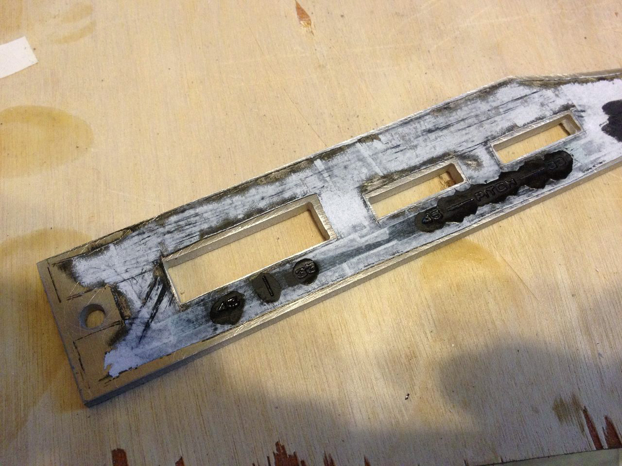
To get the black lettering effect I wanted, I filled in all the graphics with a generous amount of black enamel paint. It looks ugly here, but you have to imagine how it will look once the surface is sanded down. Everything will be returned to bare metal except for the etched bits.
Sand down the surface and you get a rather nice looking etched panel:
Going back a bit, here's some shots of the other metal pieces and other parts of the process:
After you iron the printed graphic toner onto the plate, it gets dunked in a bath of cold water. The paper soaks, allowing you to peel it away leaving only the toner adhered to the plate.
And here it is in the saline sulphate etching solution. Bubbles rise from the exposed bits and it generates a brown, rust-like by product:
Mounds of the byproduct protrude directly from the etching graphics:
Wipe it down, peel off the tape, paint the graphics black, and sand the surface down and you get this:
I was pretty happy with how these came out. It was my first time experimenting with etching, and know it won't be my last. It did take a bit of trial and error though.
I achieved the brushed aluminum finish using 60 grit sand paper, a sanding block, and a jig to keep the sanding motion perfectly parallel with the plate. It could probably use a bit deeper of a sanding, as there are still a few stray scratches that really stand out in certain lighting.
NEXT STEPS:
01) Finish building wood case, and stain it.
02) Once case is stained, install faceplates and begin mounting components.
03) Fabricate internal brackets and standoffs for all the various components that need to be secured
04) Wire everything together.
Last edited:
 This is just awesome. Great work.