My 1080 Ti completely stopped working mid game. Please help me!

Well how I exactly I do that? Do I have to solder a wire if so on which coil, which side, to the coil with the complete mosfet or the one I removed, or both? Thank you.
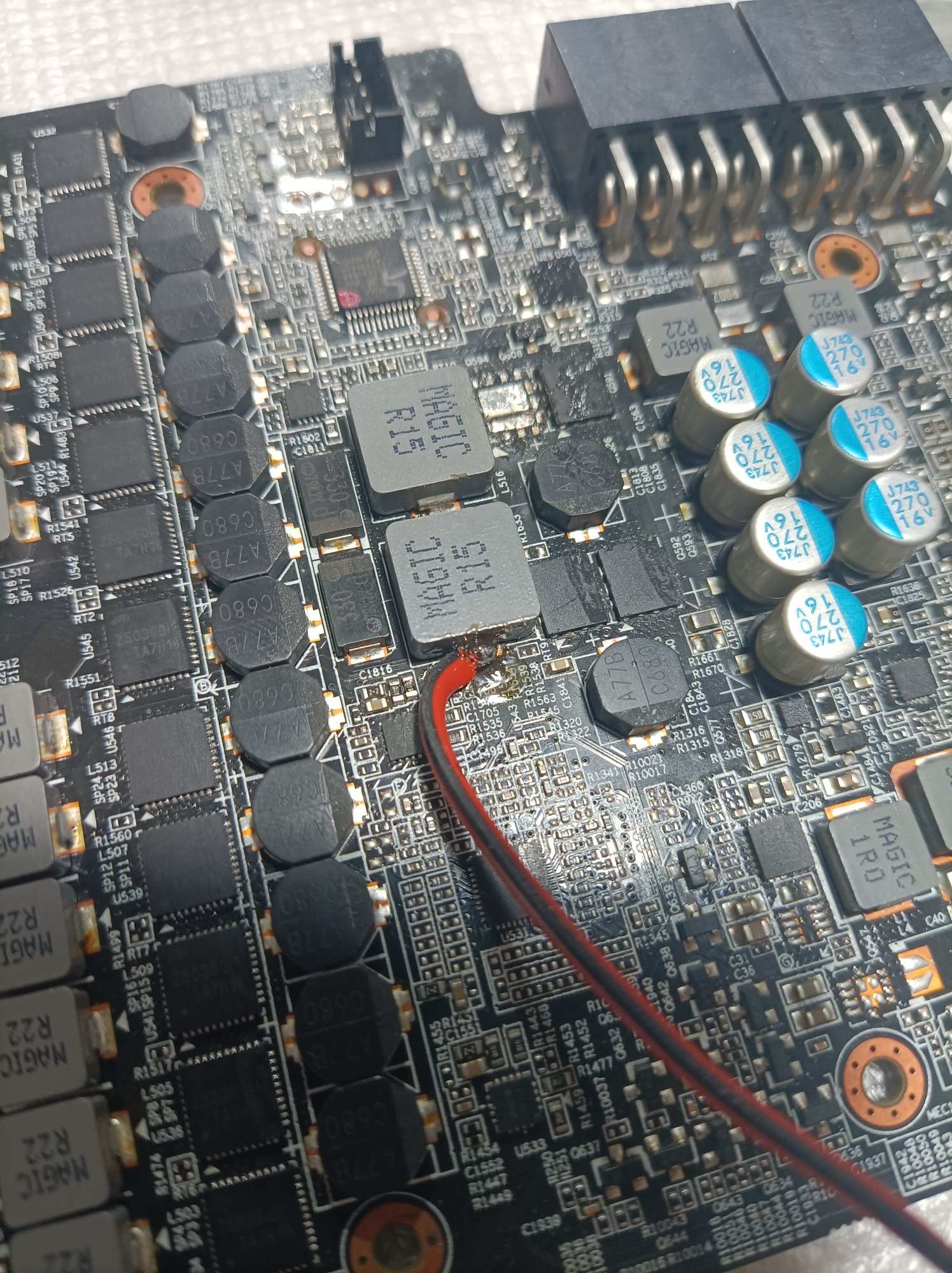
You can solder the wire to either end of any of the coils on that VRM. It doesn't really matter which end, or which one you choose, since they're all wired up together, and the coils don't have a meaningful effect if you're supplying a constant voltage.

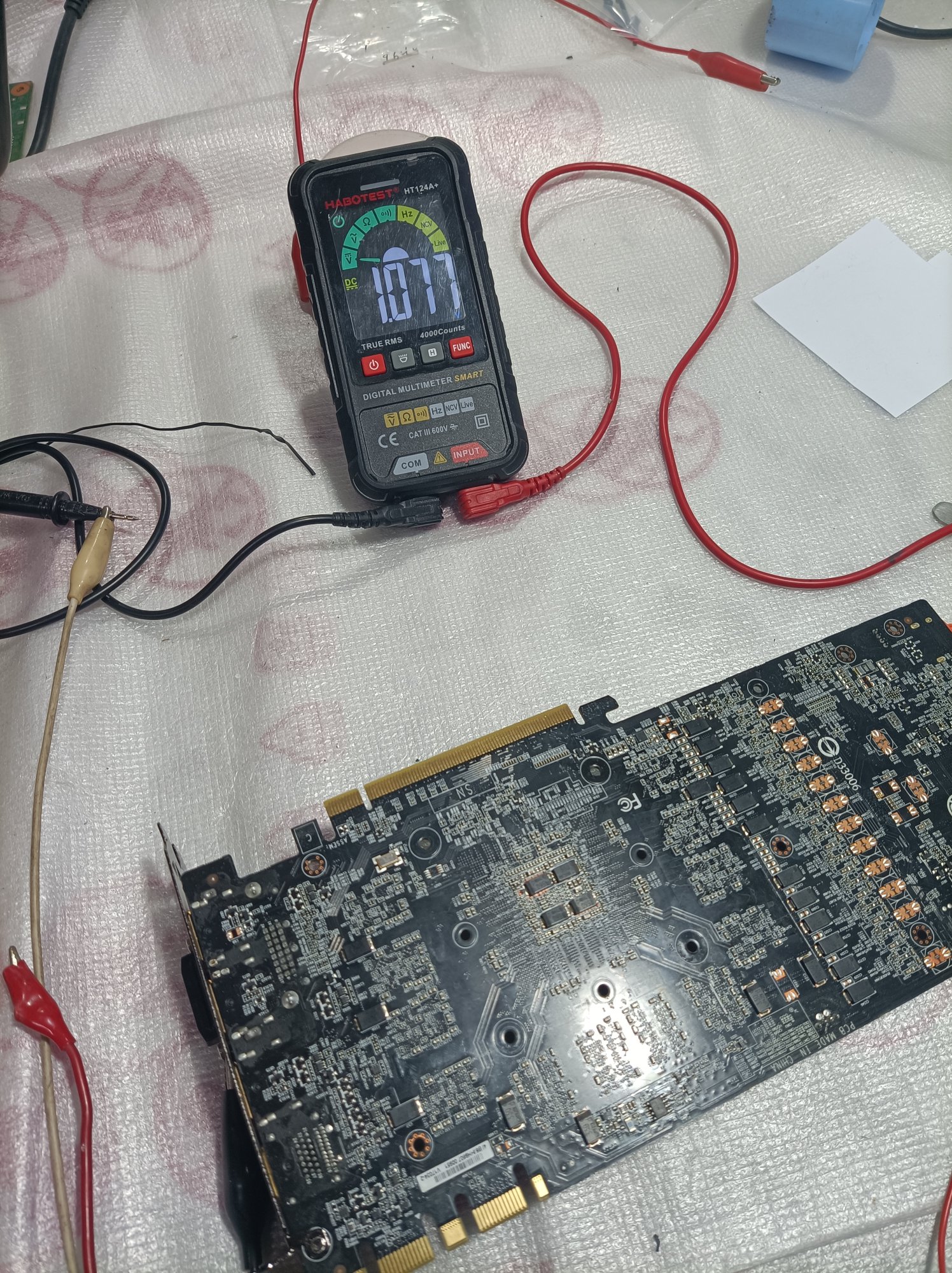
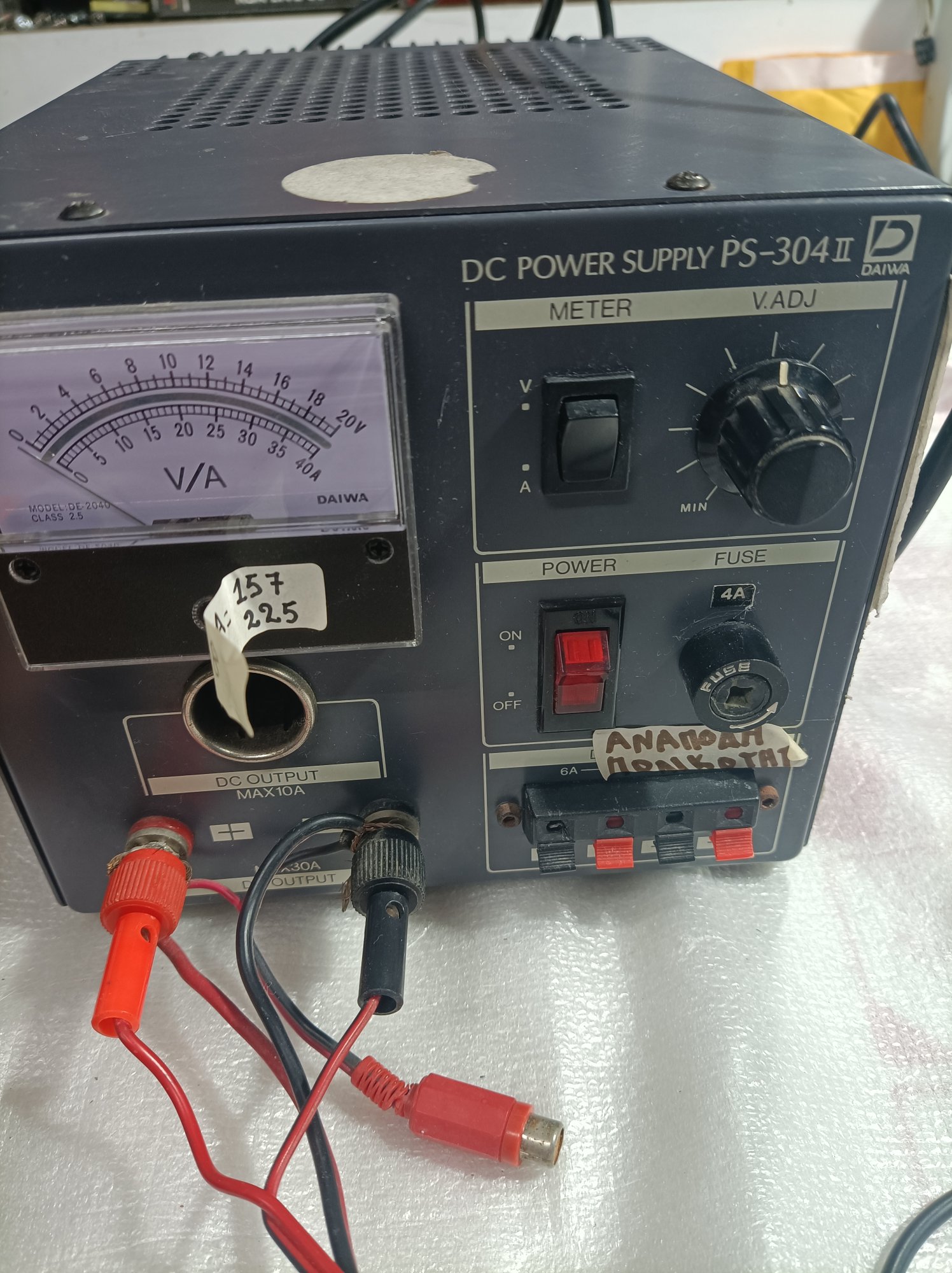
Obviously, the other end of the wire should be connected to the positive terminal of the power supply, and you need to connect the negative terminal to the ground plane on the board. If your power supply has alligator clips, just the clip the negative terminal to the slot plate.
 
As I understand this will feed the vrams only or also the memory controller on the gpu chip? Should I start at low 1-2A and if nothing gets warm increase or straight 10A. Do I need to put a heatsink on the gpu chip?
 
As I understand this will feed the vrams only or also the memory controller on the gpu chip? Should I start at low 1-2A and if nothing gets warm increase or straight 10A. Do I need to put a heatsink on the gpu chip?
You can try to start with just 1-2A if you want, but I would guess that you won't get enough temperature delta with less than 10A to be able to tell, unless you have a really good thermal camera.

You should not put a heatsink on the GPU - you actually want to see the die itself, so you can see if there's one spot on it that gets hot.

1 tiny spot that gets hot = probably bad GPU die
Whole thing gets a little warm = normal

What you're really looking for, though, is other components that get hot when you inject current, like a cracked MLC capacitor or MOSFET, or even a spot on the board itself.
 
But I do bypass the mosfet since I feed the coils or not? What follows after the coil is the vram or some capacitor/s?
 
But I do bypass the mosfet since I feed the coils or not? What follows after the coil is the vram or some capacitor/s?
No. You're injecting voltage into the memory power plane - it will reach all of those components, and then flow (mostly) through the one with the lowest resistance, dissipating energy as heat.

No need to do anything other than solder a wire to the coil terminal, supply 1.0V, and look for whatever gets hot. No heatsinks. No extra jumper wires. No "bypassing" anything. Just solder the wire and apply voltage.
 
I did solder the wire 1v and 10A, it seems the card does not get anything she stays cold. What now?
 
It's like there is no current going in the card, card is cold. I'm in a basement it's like 14C card same, with hand and infrared thermometer.
 

Attachments

  • 17050842824461785530479855434907.jpg
    17050842824461785530479855434907.jpg
    642.9 KB · Views: 0
Try putting some isopropanol on some of the suspect components, such as the FETs and the GPU die, and then turn the power supply on and leave it on for a couple of minutes, while you watch to see where the alcohol evaporates the fastest.

If you still don't see anything, start checking other components, like the MLC caps, keeping in mind that most of the ones on the back behind the GPU die are attached to this circuit, as well as the ones behind and around the memory ICs.
 
OK I understand all, but this card remains ice cold,i will leave it few minutes. How can I be certain if the card gets the amount of voltage and A?
 

Attachments

  • 1705085211059554813881501168512.jpg
    1705085211059554813881501168512.jpg
    828.6 KB · Views: 0
I have a power meter in the wall socket, when, I make the connection the consumption goes up 20w, so it seems she is getting fed, but I fail to see if so any change in Temps.
 
How are you supplying the voltage? A bench power supply should tell you how much current it's applying.

Did you try the isopropanol technique I mentioned? Watching the isopropanol evaporating is probably the best way, other than a thermal camera or freeze spray. Using your fingers won't likely be useful, but your lips might (seriously).
 
I used this a bench powersupply older one, what I saw that there not much current maybe 1. Device is capable of 10 and more,.
 

Attachments

  • 17050867874892678394380573049803.jpg
    17050867874892678394380573049803.jpg
    445 KB · Views: 1
You still think despite the power supply showing 1A (its like there was no current going in the Card, dotn know why) that an evaporation test will show a faulty component. Shouldn't the powersupply show 10A if the card was capable of demand/draw? Card was ice cold not the slightest change in anything.
 
You still think despite the power supply showing 1A (its like there was no current going in the Card, dotn know why) that an evaporation test will show a faulty component. Shouldn't the powersupply show 10A if the card was capable of demand/draw? Card was ice cold not the slightest change in anything.
Generally yes, but it doesn't always work, especially when the short is still fairly high in resistance, as yours is, and thus doesn't flow much current. The best tools to locate the warm spots on the board are, in this order:

1. a thermal camera
2. freeze spray
3. isopropanol
4. your lips
5. your fingers

https://www.fs-pcba.com/pcb-short-c...iest way to tell,to the burning of components.

If you're having trouble getting the isopropanol to evaporate, you might try taking the board to a warmer space. I'm in Texas, so it's usually around 25 degrees C in my house, and that test usually works, but I could imagine it's possible to have the room be cold enough that the alcohol doesn't evaporate fast enough to see.

If the current injection just isn't working, and you can't see anything obviously wrong with a visual inspection, you can try guessing where the current is going, and just start removing stuff, keeping in mind that:
1. The resistance of most of the circuits drops when you heat the board up, so you'll need to heat it up, remove something, and then let it cool back down before you check the resistance
2. Every time you heat the board up, you have the very significant potential to damage the remaining FETs, so it's best not to guess wrong too many times.
3. It's possible, even likely, that the short is inside a component you can't remove, such as the large BGA components or the board itself.
 
If there is still fairly high resistance, it might be safe to just replace the fuse, then apply normal power to the card while checking for hotspots, and be ready to cut power instantly. If the fuse blows again, the offender will at least get hot and stand out, thus be located. This test might only take 5 seconds for something to show as very warm or hot.. and you wouldn't want to run a graphics load on it with heatsink off. But a quick power on while pc is posting for 5 to maybe 10 seconds should be safe for the GPU, hopefully long enough to find the hotspot. Then go from there. Don't let windows boot.

If those resistance tests were reading a near short, then you would blow another fuse to find the shorted component. But if it's high enough, you probably have some time before the fuse blows, to spot the component, and then power off before the fuse blows. I suspect it would take a graphics load to pop the fuse again. But if you buy a replacement fuse, be sure to get multiple.

This way could cost you a fuse, but will take a lot of the guesswork out. The fuse will blow before the card damages itself.

Take pics with your flir when you try this, and I recommend having a helper whose job is to pull the power at a moments notice, while you are manning the camera. If it's a flir for your cell phone, take video of the 10 second power on test. It's possible that the hotspot could be something on the backside, so if 10 seconds goes by and nothing is getting hot on the GPU side, check the back real quick.
 
OK I managed the current injection. I measured 1.1v on the coils and also on the small caps on the backside of the memory chips. The card got little bit warm, memory chips gpu core in general felt warm. I used a cell phone flir camera which didn't show any significant thermal delta on a specific point.
 
Last edited:
Has baking the gpu come into the conversation? I saved a 9700pro with that. Doesn’t always work but can reset solder connections and fix things in some situations.

Oh nvm … didn’t notice the dates and the updates … heh.
 
Has baking the gpu come into the conversation? I saved a 9700pro with that. Doesn’t always work but can reset solder connections and fix things in some situations.

Oh nvm … didn’t notice the dates and the updates … heh.
In this situation, that's likely to make things worse, and not better. Hardgfg's card has experienced a failure in the memory VRM that's created a fairly high resistance short to ground. This isn't an issue of the BGA solder joints failing - something else on the board has most likely melted. If I had to guess, I'd say it's most likely inside the GPU, but at this point, it might be worth removing the low-side FETs from the memory VRM to see if that clears the short.

It most likely wouldn't have helped the OP's card, either, because that card suffered a similar failure, and no amount of baking would fix that. :(
 
Yeah when I read through it seemed like some kind of power delivery issue … or failed power protection and the gpu got an unhealthy dose of voltage.. it was late and that comment was very off the cuff. Thanks for your explanation.
 
With lowside mosfets you mean the 3 remaining mosfets in the area where i removed the one who was initially off? Some other people suggest to remove the Vram coils and check the resistance
 
Last edited:
With lowside mosfets you mean the 3 remaining mosfets in the area where i removed the one who was initially off? Some other people suggest to remove the Vram coils and check the resistance
I really meant just the low side FETs, which are the ones that stand between the switch node and ground in the buck converter (you should really read about how a buck converter works before you do anything else).

Each "phase" in the VRM has two transistors - a high side, which switches the 12V supply to the logic, and a low-side, which switches the flyback current when the high side is turned off. The transistor you removed is that phase's high side FET. The other is the low side FET. If you look at a schematic, you'll see that the low side FET sits between the switch node ( the coil terminal where you've been measuring ~5 ohms to ground) and ground. So, a failure of that FET could create your 5 ohm short to ground.

Especially if you used something other than a PCB preheater and a precise hot air rework station, for instance, a heat gun, to remove that high side FET, the low side FET being damaged is a very likely potential cause for your short.

So, I suggest removing the low side FET from the phase you've already been working on since that's the one that's most likely to be damaged, and if that doesn't work, remove the other two and see if that clears it.

Edit: If removing the low side FET(s) clears the short, plan on replacing all four of the FETs in that VRM with new ones, if not also the ones in the core VRM. When one fails, the others are usually also degraded, and the heat you likely had to use to remove the first one probably damaged them further.
 
Last edited:
I heated the pcb with a heatgun even as i could and used the smallest nostril on the rework station for removing the vram mosfet. I will try to remove the other vram mosfet and check .

Whats your take on removing the coils as others suggest and do a check ?
 
I heated the pcb with a heatgun even as i could and used the smallest nostril on the rework station for removing the vram mosfet. I will try to remove the other vram mosfet and check .

Whats your take on removing the coils as others suggest and do a check ?
What was the result of removing the low side FET? Did that clear your short to ground?

Removing the coils might help. That effectively breaks the circuit in half - you've got the VRM half on one side, and the logic side on the other. You can then check each side for a short separately, and it can help with making current injection testing more effective, since you're only testing one side a time.

Removing the coils without a PCB preheater is a pain, though. You need a TON of heat to get them hot enough to remove, which, again, has the potential to damage all the semiconductors on the board.
 
Back
Top