![[H]ard|Forum](/styles/hardforum/xenforo/logo_dark.png)
larrymoencurly
[H]ard|Gawd
- Joined
- Jul 18, 2002
- Messages
- 1,635
I have some 350W Fortron-Sparkle model FSP-350BU PSUs with empty spots where a thermistor and fixed resistor would normally be connected in series, and I'd like to know their purpose. I think that they connect this way:
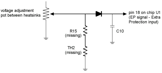
Capacitor C10 and pin 18 are on the small vertical circuit board (beneath the removed fan controller board in the photo below) housing the Fairchild KA3511DS PSU controller chip, and according to the URL=http://www.ortodoxism.ro/datasheets/fairchild/KA3511.pdf]Data sheet for KA3511DS[/URL], pin 18 is the Extra Protection (EP) input, which is supposed to shut down the PSU if its voltage goes high. In other words, this seems to rule out the thermistor being used as a overheat sensor because the pin 18 is low anyway in normal operation.
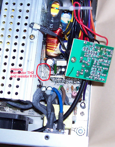
Here are where the missing resistor and thermistor are located (circled in red):
Capacitor C10 and pin 18 are on the small vertical circuit board (beneath the removed fan controller board in the photo below) housing the Fairchild KA3511DS PSU controller chip, and according to the URL=http://www.ortodoxism.ro/datasheets/fairchild/KA3511.pdf]Data sheet for KA3511DS[/URL], pin 18 is the Extra Protection (EP) input, which is supposed to shut down the PSU if its voltage goes high. In other words, this seems to rule out the thermistor being used as a overheat sensor because the pin 18 is low anyway in normal operation.
Here are where the missing resistor and thermistor are located (circled in red):