Laptop Killing Booby-Trapped USB Drive

I am not a power guy, I only know the basics. Still, to me, this sounds basicly like bullshit. Charging capacitors to -110v? from across the USB bus? Sounds like absolute BS to me. The only thing in your PC, Laptop or otherwise, that sees anything beyond 12v is the power supply because it is drawing 110v / 220v from the outlet. From there voltage is reduced to 12v / 5v / and 3.5v if I remember correctly. Nothing I know of including a capacitor could hope to hold 110v.

Add to that this language, "...as we need the N-channel field resistor, which, unlike the P-channel one, can have larger current for the same dimensions." current isn't measured as voltage, it's measured as amps but the guys says nothing anywhere about amps, all he talks about is voltage. He is talking about commuting the current.

Definition of COMMUTATE
transitive verb
: to reverse every other half cycle of (an alternating current) so as to form a unidirectional current

If I have this understood, commutation is basically what happens when you convert AC to DC. The problem is there is no AC current in a computer beyond what happens in the power supply. I just don't see how this could possibly be functionally true.

Maybe someone here knows enough more then I to explain it.
 
But would this actually kill a laptop or just the USB it charges then discharges 110v into the USB and then goes back into a recharge cycle if 5v is still present... I would think it would work once then some fuse on the USB bus would jump into that grenade and that port would be dead.
 
I wouldn't be surprised if all it took out was the USB controller, though a computer without input would rather suck.
 
It uses a DC-DC converter. This basically "chops" the DC into AC, then uses an inductor and/or capacitor to create a higher (or lower) DC voltage. It's called a boost converter if the voltage goes up and a buck converter if it goes down. Google LM2577 for a good example of a boost converter.

That being said, this is BS. At best you would kill the USB controller, but once that's gone it won't get the juice for a second pulse, and even if it did, no power would flow backward through a blown USB controller.
 
I am not a power guy, I only know the basics. Still, to me, this sounds basicly like bullshit. Charging capacitors to -110v? from across the USB bus? Sounds like absolute BS to me. The only thing in your PC, Laptop or otherwise, that sees anything beyond 12v is the power supply because it is drawing 110v / 220v from the outlet. From there voltage is reduced to 12v / 5v / and 3.5v if I remember correctly. Nothing I know of including a capacitor could hope to hold 110v.

Add to that this language, "...as we need the N-channel field resistor, which, unlike the P-channel one, can have larger current for the same dimensions." current isn't measured as voltage, it's measured as amps but the guys says nothing anywhere about amps, all he talks about is voltage. He is talking about commuting the current.


If I have this understood, commutation is basically what happens when you convert AC to DC. The problem is there is no AC current in a computer beyond what happens in the power supply. I just don't see how this could possibly be functionally true.

Maybe someone here knows enough more then I to explain it.

I didnt read the article, but capacitors can be charged to very high voltage from a very low voltage.

Think about old school film cameras, they normally used 2 AA batteries but charged the capacitors to high voltages in order to operate the flash.
 
I am not a power guy, I only know the basics. Still, to me, this sounds basicly like bullshit. Charging capacitors to -110v? from across the USB bus? Sounds like absolute BS to me. The only thing in your PC, Laptop or otherwise, that sees anything beyond 12v is the power supply because it is drawing 110v / 220v from the outlet. From there voltage is reduced to 12v / 5v / and 3.5v if I remember correctly. Nothing I know of including a capacitor could hope to hold 110v.

Add to that this language, "...as we need the N-channel field resistor, which, unlike the P-channel one, can have larger current for the same dimensions." current isn't measured as voltage, it's measured as amps but the guys says nothing anywhere about amps, all he talks about is voltage. He is talking about commuting the current.


If I have this understood, commutation is basically what happens when you convert AC to DC. The problem is there is no AC current in a computer beyond what happens in the power supply. I just don't see how this could possibly be functionally true.

Maybe someone here knows enough more then I to explain it.
It is rather complicated but this uses a DC to DC inverter to charge a number of caps that when full trip the discharge of roughly 110v until the discharge level drops to -7v dc. Thus this device delivered 110v@??? Amps to the data and 5v and ground lines of the USB last I checked had several protections vs this type of thing mostly fuses and diodes. From what I gather this USB bomb is like a tazer.
 
I am not a power guy, I only know the basics. Still, to me, this sounds basicly like bullshit. Charging capacitors to -110v? from across the USB bus? Sounds like absolute BS to me. The only thing in your PC, Laptop or otherwise, that sees anything beyond 12v is the power supply because it is drawing 110v / 220v from the outlet. From there voltage is reduced to 12v / 5v / and 3.5v if I remember correctly. Nothing I know of including a capacitor could hope to hold 110v.

Add to that this language, "...as we need the N-channel field resistor, which, unlike the P-channel one, can have larger current for the same dimensions." current isn't measured as voltage, it's measured as amps but the guys says nothing anywhere about amps, all he talks about is voltage. He is talking about commuting the current.


If I have this understood, commutation is basically what happens when you convert AC to DC. The problem is there is no AC current in a computer beyond what happens in the power supply. I just don't see how this could possibly be functionally true.

Maybe someone here knows enough more then I to explain it.

There is a DC/DC charge pump. It is a very small IC at the top left of the pictures you see that takes a DC voltage and spits out another by using switched charge pumping inside. If you have two capacitors inside the chip (usually they are integrated), and run the USB 5V across each capacitor in parallel, you have 2x5V charged capacitors. If you suddenly switch this orientation to series, you now have 5V across each capacitor in series which is 10V in total. That's how a charge pump operates by constantly switching between series and parallel mode with some fancy control logic and so on to increase the output voltage at the expense of current (since total power is conserved with a bit of waste at the pump). It is the capacitor version of a inductor-based transformer.

These things are used every where in consumer devices to step up the voltages and also create a negative voltage rail from a single input rail. Here it is used in a sinister way. I am not sure how well this USB would fry all the devices since some USB have common mode filters and isolators at the outputs, which are capacitively coupled. The transient may be big enough to damage some though.
 
I wouldn't be surprised if all it took out was the USB controller, though a computer without input would rather suck.

Depends on the amount of energy of the "evil device". You are correct that driving negative voltage into the ground or +5 rail would only take out the USB chip since hte internal juice of the laptop would just absorb it. But putting this into the signal chain might propagate fault further into the system. If they wanted to have fun...getting this to a couple of kV with bit more juice behind it might have a better effect.
 
If you don't know where it's been, don't stick it in.

Saying has multiple applications. May save your life one day.
 
Huh?

AC what?

No, it uses the USB power to charge up an internal -110V DC charge of sufficient power that when it then uses this to fire the -110V DC back into the 5V and 3.3V power lines (which are usually just connected to the power planes on your computer's motherboard .... it will fry all the chips in the system. I assume even the memory chips in SSD drives. Though this won't affect magnetic data stored on hard drives (though the drive's electronic components will also be fried.

I have no idea, but I'm just assuming the goal is to fry and make useless a computer so as to stop law enforcement or someone else from getting access to it?

Not sure any of the motherboard manufacturers have isolated the USB power to the connectors other than maybe a surface mount fuse.

I would assume something designed to be "hardened" would actually have isolated power/ground on all external connections so getting zapped by EMP or anything else would be prevented.

Sounds like this could definitely ruin someone's day as a prank. :eek:
 
Huh?

AC what?

No, it uses the USB power to charge up an internal -110V DC charge of sufficient power that when it then uses this to fire the -110V DC back into the 5V and 3.3V power lines (which are usually just connected to the power planes on your computer's motherboard .... it will fry all the chips in the system. I assume even the memory chips in SSD drives. Though this won't affect magnetic data stored on hard drives (though the drive's electronic components will also be fried.

I have no idea, but I'm just assuming the goal is to fry and make useless a computer so as to stop law enforcement or someone else from getting access to it?

Not sure any of the motherboard manufacturers have isolated the USB power to the connectors other than maybe a surface mount fuse.

I would assume something designed to be "hardened" would actually have isolated power/ground on all external connections so getting zapped by EMP or anything else would be prevented.

Sounds like this could definitely ruin someone's day as a prank. :eek:

It would likely not go past the USB controller chip in most computers, laptop or not. The power circuitry is not connected everywhere whether there is fuses or not. This device sends the power on the signal wires only as it needs the 5V lines for charging itself. The upstream USB chipset controller logic has plenty of gates/transistors, many of which are fail-open as well as some of the capacitors inline in the signal wires. Fail-open is really a big deal in modern electronics so that faults in one section doesn't propagate into another. With only 110V or so on tap, this thing can't "pierce" (dielectric breakdown) most of the dielectrics after just one or two devices fail-open inside the controller logic. I don't see it zapping everything down to the SSD, since those buses are all isolated and there are tons of devices (transistors/capacitors/inductors/etc) inline.
 
It uses a DC-DC converter. This basically "chops" the DC into AC, then uses an inductor and/or capacitor to create a higher (or lower) DC voltage. It's called a boost converter if the voltage goes up and a buck converter if it goes down. Google LM2577 for a good example of a boost converter.

That being said, this is BS. At best you would kill the USB controller, but once that's gone it won't get the juice for a second pulse, and even if it did, no power would flow backward through a blown USB controller.

And I seen plenty enough caps near a CPU socket and those are at most 12v caps. Any of you guys see even one cap that looks the same on the pic of this USB device?
 
I didnt read the article, but capacitors can be charged to very high voltage from a very low voltage.

Think about old school film cameras, they normally used 2 AA batteries but charged the capacitors to high voltages in order to operate the flash.

I understand, but I still don't see anything that looks like a cap on the pic of that USB device. Maybe it's on the back ?
 
Huh?

AC what?

No, it uses the USB power to charge up an internal -110V DC charge of sufficient power that when it then uses this to fire the -110V DC back into the 5V and 3.3V power lines (which are usually just connected to the power planes on your computer's motherboard .... it will fry all the chips in the system. I assume even the memory chips in SSD drives. Though this won't affect magnetic data stored on hard drives (though the drive's electronic components will also be fried.

NO JUST NO. The connected device is a fixed energy source. If I apply -110V from an infinite source (e.g. a wall supply), you are right. But in this case, the amount of energy stored by the thumb drive probably wouldn't make a dent in the rails.

Energy = 1/2 C*V^2. That is what the thumb drive has. No more...no less. In this case C is very small (maybe a few uF). The amount of capacitance on the mobo will swamp that.

Again..as stated, it will probably burn out the USB power controller..but that is it.
 
I see how the theory is on it, could be off but here is my best guesstimate:

They are using 12 capacitors, however only using -110V. So to get to that voltage they are charging 2 capacitors in parallel, so 5V each. Once they are charged those two disconnect from the USB VCC+/VCC- power and sets them in series, so 10v between the two and either charges the other 10 caps, probably in series/parallel, so the end result is one cap is -10v. Disconnect power from the series caps and put them back in parallel and switch input power back to USB. Repeat for the other 9 capacitors. Once -110v is achieved send the power to Data+/Data- only, and repeat if VCC+ and VCC- are still receiving power.

Best part is no drivers required! It may not be enough to cause your computer to catch fire, but any IC can be very sensitive to massive sudden power surges. A slight pop of the USB controller is enough to take out the motherboard, especially motherboards with the USB controller integrated into the southbridge.
 
And I seen plenty enough caps near a CPU socket and those are at most 12v caps. Any of you guys see even one cap that looks the same on the pic of this USB device?

These are much higher voltage rated ceramic surface mount capacitors (google it if you want to see more). These are the brown-yellowish blocks you see on the PCBs of which there are larger ones (for energy storage) and smaller ones on the flip side (for the charge-pump, presumably).

You don't see these often in this size on computer boards because these are super expensive at higher capacitances and are not space efficient. The main reason why this device uses these capacitors is for a good ratio between voltage rating and being low-profile.
 
I understand, but I still don't see anything that looks like a cap on the pic of that USB device. Maybe it's on the back ?

Just FYI, there are many different varieties of capacitors based on shape alone. The ones in the microwave ovens and your furnance looks like a small metallic can, the old tube radio ones look like a wax candle with paper covers, the ones in your old transistor radios looked like a candy with legs and so on. It is all based on construction and application. There are miniscule capacitors that are any colored and could be any plastic/metal/ceramic construction. These are used a lot on condensed circuitry that is found in phones/pads/portable computers lately.
 
I understand, but I still don't see anything that looks like a cap on the pic of that USB device. Maybe it's on the back ?

The physical size of a ceramic capacitor doesn't tell you a whole lot about its voltage rating or it's capacitance really. It can to a degree, but you can for example buy a 100V rated MLCC capacitor at 20+uF that's about 1/4"x1/4". 20ish uF isn't really that high, but the ones on that PCB look like they could be a little higher. With other types of capacitors (mainly film types) the physical size will change fairly dramatically with voltage and capacitance values.

There could be enough power on that little board to do some damage. How much is the question. Also, a lot of logic circuits (especially CMOS types) do not like negative voltages at all. Depending on the protection scheme for this type of input, this could get past that, and do a little damage.

This actual device may or may not do more damage than just fry a controller, but you wouldn't catch me plugging one into any of my ports. :D
 
Wow, a thread full of experts, and most of you don't know wtf your'e talking about.

I won't plug that into my pc's.... and it likely would fry most all the chips.
 
Wow, a thread full of experts, and most of you don't know wtf your'e talking about.

I won't plug that into my pc's.... and it likely would fry most all the chips.

I don't know who you are aiming at, but if you have some interesting opinions on the topic rather than others who are discussing it, please do share.
 
I think this is more designed to plug into someone else's laptop to attempt to damage it, or to be made as counterfeit products to be mixed in with legitimate items. You buy what you think is a legitimate memory device, and it turns out one of these is in their instead.

As for all the arm-chair speculation about whether this would or would not work... this is why real science is rooted in empirical observation, not hypothesis. Nobody, except perhaps the people who have made this device, have observed whether or not it even functions at all. There's absolutely no way to know what kind of harm it may or may not do until someone tests one and observes the results.
 
I think this is more designed to plug into someone else's laptop to attempt to damage it, or to be made as counterfeit products to be mixed in with legitimate items. You buy what you think is a legitimate memory device, and it turns out one of these is in their instead.

As for all the arm-chair speculation about whether this would or would not work... this is why real science is rooted in empirical observation, not hypothesis. Nobody, except perhaps the people who have made this device, have observed whether or not it even functions at all. There's absolutely no way to know what kind of harm it may or may not do until someone tests one and observes the results.

Kinda what I was thinking.

I am not knowledgeable enough in electronics to have an educated or accurate guess if this would work or not.

My thought was, is there a way to get a hold of and/or recreate such a device and does anyone have a laptop ready to give up it's life in the name of research.

I would think an older laptop :)

Question: With the USB controllers and sockets on computers adn devices, does the power line come though the controller and data channels or does it pretty much come straight from the power supply.

Is the ground for everything on the motherboard common?

Thanks
 
I'd be far more effective if it squirted water and started shorting out components. Harder? maybe but definitely a better shot at destroying a *ahem* targets laptop.
 
I see how the theory is on it, could be off but here is my best guesstimate:

They are using 12 capacitors, however only using -110V. So to get to that voltage they are charging 2 capacitors in parallel, so 5V each. Once they are charged those two disconnect from the USB VCC+/VCC- power and sets them in series, so 10v between the two and either charges the other 10 caps, probably in series/parallel, so the end result is one cap is -10v. Disconnect power from the series caps and put them back in parallel and switch input power back to USB. Repeat for the other 9 capacitors. Once -110v is achieved send the power to Data+/Data- only, and repeat if VCC+ and VCC- are still receiving power.

Best part is no drivers required! It may not be enough to cause your computer to catch fire, but any IC can be very sensitive to massive sudden power surges. A slight pop of the USB controller is enough to take out the motherboard, especially motherboards with the USB controller integrated into the southbridge.
I like the idea of switching capacitors from parrrallel to series, but I suspect the pulse goes back over power. That way the whole board sees it and if they do a shock pulse, nothing can react to the spike but at the same time its not enough to fry anything closed. Most USB devices are passively powered and others would be assumed to be well behaved as part of the spec so for cost savings I doubt very few PC's are hardened/isolated against voltage spikes on the USB power so everything gets exposed. The pulsing could be dozens or hundreds of times a second. Its like having a dirty power supply except intentionally dirty. Everything will suffer.
 
I think this is more designed to plug into someone else's laptop to attempt to damage it, or to be made as counterfeit products to be mixed in with legitimate items. You buy what you think is a legitimate memory device, and it turns out one of these is in their instead.

As for all the arm-chair speculation about whether this would or would not work... this is why real science is rooted in empirical observation, not hypothesis. Nobody, except perhaps the people who have made this device, have observed whether or not it even functions at all. There's absolutely no way to know what kind of harm it may or may not do until someone tests one and observes the results.

This is true, no way to know outside testing it. However to be fair there is some room for them to be extremely skeptical. Delivering a system shock capable of blowing the entire machine through the USB bus isn't as clear cut as it would seem. I would put it in the category of "plausible". I've seen computers blown out from a electrical surge through the ethernet port, so based on the same principle It is possible. Though more often then not I've simply seen the port itself blown and the rest of the PC be fine. So I would expect that most likely it will just blow the port, but it has a fair chance of probability to succeed in taking the entire board. So all in all I would say that yes this is possible, just not probable in most cases.
 
This is interesting, would like to see some testing to prove if this is actually possible. Maybe the "H" could do a mythbusters video on this little evil device. :D
 
... i do have an old dell laptop that could be sacrificed for science of course.
 
Would have used a drive last night if I had remembered to bring it home so i could transfer the rest of the Archer Season with me to work.
 
I think this is more designed to plug into someone else's laptop to attempt to damage it, or to be made as counterfeit products to be mixed in with legitimate items. You buy what you think is a legitimate memory device, and it turns out one of these is in their instead.

As for all the arm-chair speculation about whether this would or would not work... this is why real science is rooted in empirical observation, not hypothesis. Nobody, except perhaps the people who have made this device, have observed whether or not it even functions at all. There's absolutely no way to know what kind of harm it may or may not do until someone tests one and observes the results.

Phoenix333, all I am saying is I am looking at the pic and I don't see a single component that even looks like a capacitor. I googled images of capacitors and scoured them looking for examples that look like the components on this board and I still don't see anything that looks like a capacitor on it. I never claimed to be an expert and stated so on my first post. I asked others and I got explanations about how capacitors don't have to be very large to hold a large charge yet this guy didn't point out which components on the PCB were capacitors.

Truthfully my gut feeling is this is a hoax. I'm not saying a device that was made to do what the article claims couldn't damage a computer. I'm just saying the device doesn't look to me like it's representative of the real deal. Come on, the PCB has "High Voltage" printed on it in English, from a Russian website. Just saying.
 
Phoenix333, all I am saying is I am looking at the pic and I don't see a single component that even looks like a capacitor. I googled images of capacitors and scoured them looking for examples that look like the components on this board and I still don't see anything that looks like a capacitor on it. I never claimed to be an expert and stated so on my first post. I asked others and I got explanations about how capacitors don't have to be very large to hold a large charge yet this guy didn't point out which components on the PCB were capacitors.

Truthfully my gut feeling is this is a hoax. I'm not saying a device that was made to do what the article claims couldn't damage a computer. I'm just saying the device doesn't look to me like it's representative of the real deal. Come on, the PCB has "High Voltage" printed on it in English, from a Russian website. Just saying.

http://www.vishay.com/capacitors/list/product-45221/
 
Kinda what I was thinking.

I am not knowledgeable enough in electronics to have an educated or accurate guess if this would work or not.

My thought was, is there a way to get a hold of and/or recreate such a device and does anyone have a laptop ready to give up it's life in the name of research.

I would think an older laptop :)

Question: With the USB controllers and sockets on computers adn devices, does the power line come though the controller and data channels or does it pretty much come straight from the power supply.

Is the ground for everything on the motherboard common?

Thanks

First thing to do is stop thinking about electrical current as something that is coming "from" somewhere. It's not being "pushed", it's being "pulled" and the way this is expressed is "draw". Electrical devices always try to draw enough current to do what they were designed to do. A 12v, .3 Amp fan will draw 3.6 watts of juice when it's running.

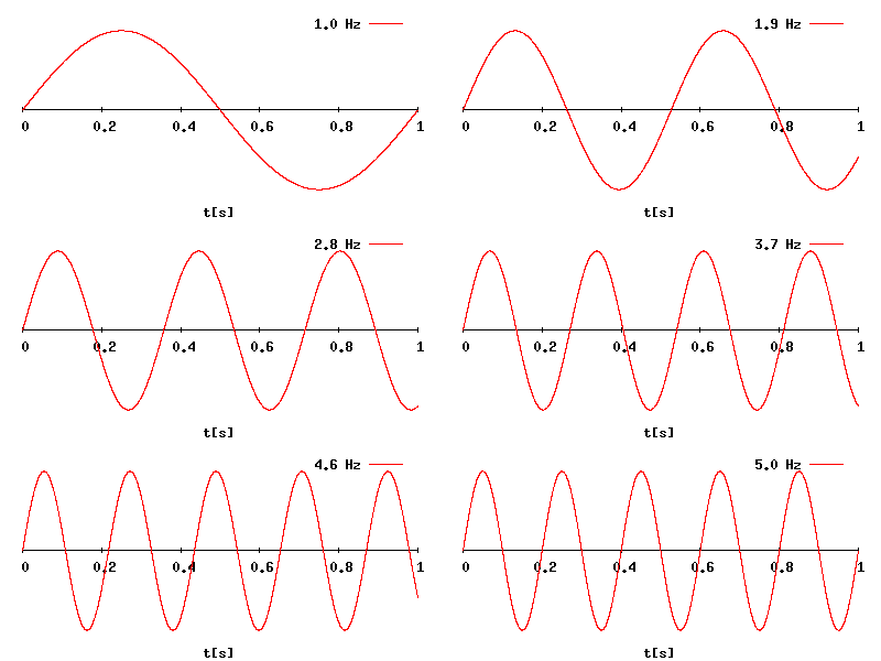
That being said, the power is always delivered down the power channels and not across data lines. That doesn't mean electricity doesn't flow along the data lines as well, it does. But that electricity is in the form of discrete and precisely controlled signals that can be measured and "read" in order to discern data. These signals are like milli-volt micro-amp type signals. You probably know how a signal is typically displayed as a wavy line. Think of each "peak" of each wave as a single pulse(cycle) of the signal, how many times the signal pulses in a second would be the frequency of the signal. 133Mhz is 133 million times a second. I hope this image of a signal that varies in frequency works. If not, there is another link to the page where it does.

Wave_frequency.gif


http://en.wikipedia.org/wiki/Hertz
 
Phoenix333, all I am saying is I am looking at the pic and I don't see a single component that even looks like a capacitor. I googled images of capacitors and scoured them looking for examples that look like the components on this board and I still don't see anything that looks like a capacitor on it. I never claimed to be an expert and stated so on my first post. I asked others and I got explanations about how capacitors don't have to be very large to hold a large charge yet this guy didn't point out which components on the PCB were capacitors.

Truthfully my gut feeling is this is a hoax. I'm not saying a device that was made to do what the article claims couldn't damage a computer. I'm just saying the device doesn't look to me like it's representative of the real deal. Come on, the PCB has "High Voltage" printed on it in English, from a Russian website. Just saying.

There are different types of capacitors with different functions and properties. The ones you are most likely thinking of are cylindrical electrolytic capacitors: http://en.wikipedia.org/wiki/Electrolytic_capacitor
The primary benefit of which is high capacitance at low cost. This device uses surface mount capacitors: http://en.wikipedia.org/wiki/Surface-mount_technology
which is smaller and a different form factor, as well as being ceramic instead of electrolytic. The benefit is size, lower leakage, and higher voltage rating, but the trade off is that there's not as much capacitance density and higher cost. Energy storage is a function of the square of voltage, so high voltage is useful in this scenario, but you can only go so high in voltage before the small size is susceptible to arcing.
 
OK, were getting closer. So tell me, why the "High Voltage" print on the PCB?

Seems the only way this makes sense is that the original device was some sort of USB amplifier or antenna and was modified for a new purpose or someone decided there was a need for a device that could destroy a computer quickly without causing great damage to the building it was in. Like a self destruct for spy laptops or a military application for destroying computers in the event a headquarters is being over run by the enemy.

problem is the real jewel is the data and not the computer itself and this device might not do that much damage to a HD before it tears up enough other stuff to just kill the comp before the drive is toast.
 
Back
Top