GPU Mini Fan Header Pinout?

Zarathustra[H]

Extremely [H]
Joined
Oct 29, 2000
Messages
38,878
Hey,

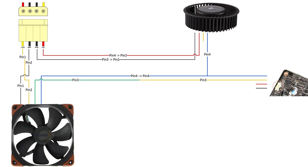
Does anyone know if the 4 pin mini fan header used on most GPU's has the same pinout as 4 pin PWM case fans?

I'm thinking I could tap into pin 4 on my GPU's and use that PWM signal to also control a bigger PWM case fan (of course, getting its power separately, wouldn't want to overload the GPU fan header)

Thoughts?
 
I am also curious about this. It looks like on GPUs they use the same 4pin headers but i think the fans are smaller.
 
Nah, they are still four pins in a row, but the connector is smaller.

If the pinout is the same I should be able to just tap into pin 4, and use it to control my case fans using one of these:

22141106114_20872b8228_b.jpg
 
Ahh yeah, i just double checked on one of my GPUs and it is 4pin but just smaller. What would the difference be between doing this and changing the fan curve on your GPU?
 
Ahh yeah, i just double checked on one of my GPUs and it is 4pin but just smaller. What would the difference be between doing this and changing the fan curve on your GPU?

Well, I'm planning on using the fan curve on the GPU to control a case fan, so that the case fan ramps up at the same time the GPU fan does, and expels the extra heat.
 
Zarathustra[H];1041950650 said:
Well, I'm planning on using the fan curve on the GPU to control a case fan, so that the case fan ramps up at the same time the GPU fan does, and expels the extra heat.

Ahh thats an interesting idea. Good luck man!
 
Zarathustra[H];1041950650 said:
Well, I'm planning on using the fan curve on the GPU to control a case fan, so that the case fan ramps up at the same time the GPU fan does, and expels the extra heat.

give us some pic's....idea sounds interesting;)
 
give us some pic's....idea sounds interesting;)

Sure thing.

Really quite simple though.

If you look at the pic above with the molex connectors, fan connectors and blue wire. All you need is something like that (I got a three way PWM splitter, and cut off the wires I didn't need) and then you connect the blue wire to the PWM wire on the GPU.

In my case there are two, because I have two GPU's and two case fans I plan on hooking up.

Once you do that, if you have a 4 pin case fan, it should obey the same duty cycle commands as the on board GPU fan does. So when the on board GPU fan is spinning at 50%, so is the case fan.

Now in my case, they aren't strictly case fans. I got a couple of Corsair HG10 N980's, which I plan to hook up with H90's in the front of my 750D.

(Click for larger)

22791608015_18d78f8707.jpg 22778098612_7d668a2ed4.jpg


22765623926_d46018d8c0.jpg 22802820901_26c5bdf027.jpg


22802825151_2fe9bf2f1a.jpg 22168885054_f970e3a25b.jpg

22168884504_101ca20372.jpg

(In that last pic, I want to join the blue wire from my PWM splitter above, with the blue wire on the GPU fan.)

Might be a while until I pull it off though, as it turns out the H90 has shorter tubing than I thought. It doesn't quite reach.

22375185847_f92cf0b18c_c.jpg


It looks like the tubes on the H90's are between 45 and 50mm (~2") too short to reach the front of the 750D :(

22793555105_626c5c1c37_c.jpg


I was suspecting they might be short, but I wasn't expecting them to be THIS short.

This isn't the end of the world, I can still work with it though. 50mm is about two fan widths, and I have found extra long radiator screws that are that long.

I can use 4 junk fans (2 for each radiator) hollow them out and just keep the frames, and then use the extra long radiator screws to attach everything.
 
Last edited:
Have you installed the cooling brackets yet? I noticed your post on the corsair forum and I noticed people were having issues with the brackets.
 
Have you installed the cooling brackets yet? I noticed your post on the corsair forum and I noticed people were having issues with the brackets.

I have not.

I am waiting for some longer screws and cheap junk fans I can gut out the centers of and use as spacers.

I have measured it, and i think it will work, but its difficult with the way the tubing bends, so I I want to verify that they will actually reach before I go ahead.

I'll post here with my experiences when I do.

My last parts arrive on Tuesday. Hopefully I will have time during the week to do it.
 
Last edited:
Looking forward to your experience and hope you do some sort of mini guide. I am sure it will help a bunch of folks, since there seems to be some confusion with installation.
 
Looking forward to your experience and hope you do some sort of mini guide. I am sure it will help a bunch of folks, since there seems to be some confusion with installation.

I'll be sure to post my experiences here after I'm done.

For now, I just made the spacers I need to make the H90's fit in the front of my case and reach the GPU's:

22436204888_f25ac1a4c8_c.jpg


Just waiting for my 2.5" (~65mm) radiator screws from Fastenal to arrive before I start putting things together.

I'm REALLY hoping I can both install these brackets without severe bending, and get a good mating surface, so my temps are good.

My suspicion is that while Corsair designed these brackets for a standard video card board layout, they can't control for how high the components sit on the board, as different GPU makers may use different components.

Because of this, the thermal tape on the back of the cards may be too thick for some applications, causing the bending some are seeing. I'm going to keep an eye on this when I install, and if I need it, get different, thinner thermal tape.
 
Question for those of you who may have played with GPU coolers before:

I plan on doing a thorough assessment of the mating of the GPU to the cooler and removing any thermal tape in the wrong spots and replacing it with thinner tape if needed during my install.

But which parts of the board (other than the GPU) are the ones that really get hot? Is it the mosfets in the VRM?
 
Did we ever get to the bottom of this pinout? It seems like it would be a standard
 
beware with the GPU pinout as I know some brands and models have different pinout than common case fans, a typical fan its Voltage(red) - Ground(black) - RPM Report(yellow) - PWM Control(blue). in some GPUs the layout is Ground(black) - Voltage(red) - RPM Report(yellow) - PWM control(blue)

a Tester/Multimeter will be always the best friend in this case.. =)
 
Did we ever get to the bottom of this pinout? It seems like it would be a standard

Yep!

I haven't installed everything yet, but I did get to messing around with the wires, my multimeter and a spare power supply.

I can confirm that the pinout is identical to a 4pin CPU fan, just smaller.

I also figured out that the blower fan spins much faster on these than I believe is necessary to cool just the VRM's, and creates an unnecessary amount of noise.

I figured out that PWM speed control still works, even after volt modding, so I decided to custom solder some wires in order to lower the blower fan speed, like this:

Click for Bigger:


And here is the end result on one of the two brackets:


Not my prettiest work, but it definitely works.

I haven't actually hooked it up to a PWM source yet, but I did hook it up to my spare PSU, and verified that the case fan spins at full speed, and the blower fan spins at ~40% speed with no PWM signal, as expected.

I then shorted the PWM input to ground to emulate 0% pwm signal. The blower fan spins down very slowly and quietly, and the case fan goes down to it's minimum speed as expected.

I won't know for sure until I actually try to drive them off of the video cards (hopefully Friday?) but for now, my two-point (0% PWM and "no PWM"=100%) suggests that this should work beautifully.
 
beware with the GPU pinout as I know some brands and models have different pinout than common case fans, a typical fan its Voltage(red) - Ground(black) - RPM Report(yellow) - PWM Control(blue). in some GPUs the layout is Ground(black) - Voltage(red) - RPM Report(yellow) - PWM control(blue)

a Tester/Multimeter will be always the best friend in this case.. =)

I have never seen a case/CPU fan with +12vdc on pin 1. Pin 1 is always ground.

Fan Pinout on all 4-pin fans that I have seen (now including this GPU blower) is as follows:

Pin1 - Ground
Pin2 - +12VDC
Pin3 - RPM signal
Pin4 - PWM

There are two different color schemes though, apart from cosmetic wires where all the wires are the same color, I have seen:

Pin1 - Black (Ground)
Pin2 - Yellow (+12VDC)
Pin3 - Green (RPM Signal)
Pin4 - Blue (PWM)

and:

Pin1 - Black (Ground)
Pin2 - Red (+12VDC)
Pin3 - Yellow (RPM)
Pin4 - Blue (PWM)

The electricals of the pins have always been the same though, despite the differing color schemes.

I'm not saying that all GPU's follow this pinout, there are likely others that don't, but it appears that at least Maxwell based oem layout boards do.
 
Last edited:
well yes, I was just saying to be sure to check with a tester. they aren't always the same... better prevent now than lament later, couple of friends have learned this in the bad way.
 
well yes, I was just saying to be sure to check with a tester. they aren't always the same... better prevent now than lament later, couple of friends have learned this in the bad way.

Of course!

In this case, I've determined it by a little deduction, as I haven't easily beena ble to get in there with a multimeter while running.

Instead I applied the voltage and fake PWM signals to the pins on the fan plug I thought they might be, and it responded as I expected, so I feel good about it.

I'd feel nervous poking in a running GPU with my multimeter.
 
Dang just read this thread. Interesting build for sure.
 
Back
Top