
Navigation
Install the app
How to install the app on iOS
Follow along with the video below to see how to install our site as a web app on your home screen.
Note: This feature may not be available in some browsers.
More options
You are using an out of date browser. It may not display this or other websites correctly.
You should upgrade or use an alternative browser.
You should upgrade or use an alternative browser.
Good compact 5.1 amplifier for PC system
- Thread starter echn111
- Start date

SJetski71
Fully [H]
- Joined
- Sep 6, 2002
- Messages
- 18,453
Thor thanks for taking the time, seriously. That looks like two ways we can wire it up.
Looks like i may try to wire it up a third way, though i haven't figured it out yet

The power switch is in-line with the power cord.
Any idea if i'd follow one of your two examples for this particular setup?
Edit: just read your edit underneath the first pic you posted. Looks like i'll jumper SW402, then strip off the white molex looking connector and direct those two black wires into CN401 (?)
Looks like i may try to wire it up a third way, though i haven't figured it out yet
The power switch is in-line with the power cord.
Any idea if i'd follow one of your two examples for this particular setup?
Edit: just read your edit underneath the first pic you posted. Looks like i'll jumper SW402, then strip off the white molex looking connector and direct those two black wires into CN401 (?)
Last edited:
Edit: just read your edit underneath the first pic you posted. Looks like i'll jumper SW402, then strip off the white molex looking connector and direct those two black wires into CN401 (?)
this, but post a pic for me befor you try and plug it in. if you would please, try and get a slightly wider angle on it if you could.
be sure to use the same guage wire for your jumper as i said, a small piece from the original (2 prong) cable will do.
SJetski71
Fully [H]
- Joined
- Sep 6, 2002
- Messages
- 18,453
will do,this, but post a pic for me befor you try and plug it in. if you would please, try and get a slightly wider angle on it if you could.
be sure to use the same guage wire for your jumper as i said, a small piece from the original (2 prong) cable will do.
will post a wider angle pic, full mock setup with jumper cable included.
If i can't post it wednesday morning then i'll definitely post it wednesday night.
SJetski71
Fully [H]
- Joined
- Sep 6, 2002
- Messages
- 18,453
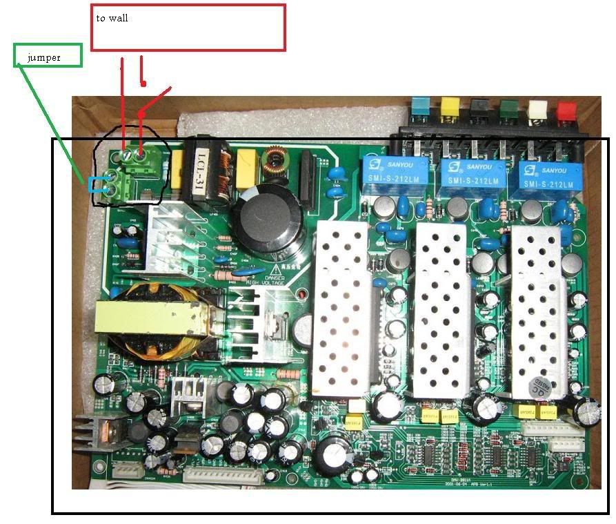
Here goes nothing, all descriptions will be underneath their respective pics:

That's the original molex power connector the seller included. Going by the pic in the PDF file, and going by shape, it would have connected to CN401 this way (the green screw terminals are not original, he added them after)

Here's how the power connector would have originally aligned with SW402

Here's my proposed setup with a mock jumper cable. Eventually i'll snip off a small piece of the same power wire.
If you look closely at the silver enclosure you'll notice some black electrical tape insulating the metal standoffs to keep them from touching the amp pcb (the fastening holes don't line up anyway). I'll say one thing, that amp fits nearly perfect in that case. One of the components is about 1/2" too tall, but i plan on snipping a hole for it at the top of the case.
echn111, how's your end coming along, are you able to make heads or tales out of Thor's examples?
That's the original molex power connector the seller included. Going by the pic in the PDF file, and going by shape, it would have connected to CN401 this way (the green screw terminals are not original, he added them after)
Here's how the power connector would have originally aligned with SW402
Here's my proposed setup with a mock jumper cable. Eventually i'll snip off a small piece of the same power wire.
If you look closely at the silver enclosure you'll notice some black electrical tape insulating the metal standoffs to keep them from touching the amp pcb (the fastening holes don't line up anyway). I'll say one thing, that amp fits nearly perfect in that case. One of the components is about 1/2" too tall, but i plan on snipping a hole for it at the top of the case.
echn111, how's your end coming along, are you able to make heads or tales out of Thor's examples?
Here goes nothing, all descriptions will be underneath their respective pics:
/snip
Here's my proposed setup with a mock jumper cable. Eventually i'll snip off a small piece of the same power wire.
If you look closely at the silver enclosure you'll notice some black electrical tape insulating the metal standoffs to keep them from touching the amp pcb (the fastening holes don't line up anyway). I'll say one thing, that amp fits nearly perfect in that case. One of the components is about 1/2" too tall, but i plan on snipping a hole for it at the top of the case.
that will work just fine.
i was wondering about the metal casing as well (how you where planing on keeping it from shorting), looks like you have a plan however.
what part is to tall? the cap? that heatsink on the left in the supply section? the supply coil? the heatsink just inside the supply section? all of the above? regardless, the cap wont be an issue, however once you have the holes cut beware that somtimes heatsinks may have voltage running through them in the KV range. high enought that you dont need to be touching ground for a good shock, it depends on what it is cooling, and weather or not he isolated it electricly (i cant tell, and the only real way to know for sure is to fire it up, find a ground and test it with a meter for current) so be sure that when you cut your holes, that there is a good ammount for room between the exposed pieces and the case, if its touching and it is carrying current you could get a nice supprise.. (and any critters passing by as well.. say a curiose cat for example... )
this could be elliminated by simply glueing a piece of plexi glass to the top of the exposed part, but if its not a problem, and you know its there, then it may not be an issue
Last edited:
SJetski71
Fully [H]
- Joined
- Sep 6, 2002
- Messages
- 18,453
Nice to have some confirmation, i can move forward nowthat will work just fine, i was wondering about the metal casing as well (how you where planing on keeping it from shorting), looks like you have a plan however. what part is to tall? the cap? that heatsink on the left in the supply section? the supply coil? the heatsink just inside the supply section? all of the above? regardless, the cap wont be an issue, however once you have the holes cut beware that somtimes heatsinks may have voltage running through them in the KV range. high enought that you dont need to be touching ground for a good shock, it depends on what it is cooling, and weather or not he isolated it electricly (i cant tell, and the only real way to know for sure is to fire it up, find a ground and test it with a meter for current) so be sure that when you cut your holes, that there is a good ammount for room between the exposed pieces and the case, if its touching and it is carrying current you could get a nice supprise.. (and any critters passing by as well.. say a curiose cat for example... ) this could be elliminated by simply glueing a piece of plexi glass to the top of the exposed part, but if its not a problem, and you know its there, then it may not be an issue
By the way, as per the pdf file, the entire section of PCB circled in white is unsafe to touch once everything is powered, and it takes a good while to dissipate once unpowered. The part that rises higher than the case is that yellow houhah in the third pic underneath my words "jumper cable" which i will have to assume is Not safe to touch. I'll glue something on top of it to stay safe, and cut out a hole big enough to give it wiggle room. And i won't not let anything conductive touch the enclosure. Going to proceed cautiously here, and will use a meter to test different parts after a very careful inspection.
I wish i knew what company used this amp. Going to search the PCB for some clues. The speaker clips look trashy compared to some nice binding posts, that might be a clue right there...
Thor, did you want me to email you a copy of the PDF file i have?
Thor, did you want me to email you a copy of the PDF file i have?
sure ill pm you my email in just a sec
Nice to have some confirmation, i can move forward now
By the way, as per the pdf file, the entire section of PCB circled in white is unsafe to touch once everything is powered, and it takes a good while to dissipate once unpowered. The part that rises higher than the case is that yellow houhah in the third pic underneath my words "jumper cable" which i will have to assume is Not safe to touch. I'll glue something on top of it to stay safe, and cut out a hole big enough to give it wiggle room. And i won't not let anything conductive touch the enclosure. Going to proceed cautiously here, and will use a meter to test different parts after a very careful inspection.
I wish i knew what company used this amp. Going to search the PCB for some clues. The speaker clips look trashy compared to some nice binding posts, that might be a clue right there...
Thor, did you want me to email you a copy of the PDF file i have?
i have been eyeing this amp myself for quite some time, i might just bite the bullet now that i have seen more info on it.. i have a logitech x530 set here (for the price, they sound great) but i have always been curiouse what they could do with more power, the jump form 7watts per sat to 25 might be a bit much, but whos saying i will ever have them up that far.. closer to 15 more likely.
the sub on this set is running 70watts, but its a very dirty 70 watts, it might be a case of less is more..
i would love to play with this my self (upgrade one of the caps to help the bass punch on 1 IC and direct that channel to the sub/center) i may have to fire off an email to this guy and see if he has provisions for it to run off of pure 12v DC... (or 12v and 5 v if it need the lower source thinking power it off my PC's psu) hmm ideas......
SJetski71
Fully [H]
- Joined
- Sep 6, 2002
- Messages
- 18,453
Someone's been bitten by the DIY bug (probably a long time ago)i have been eyeing this amp myself for quite some time, i might just bite the bullet now that i have seen more info on it.. i have a logitech x530 set here (for the price, they sound great) but i have always been curiouse what they could do with more power, the jump form 7watts per sat to 25 might be a bit much, but whos saying i will ever have them up that far.. closer to 15 more likely.
the sub on this set is running 70watts, but its a very dirty 70 watts, it might be a case of less is more..
i would love to play with this my self (upgrade one of the caps to help the bass punch on 1 IC and direct that channel to the sub/center) i may have to fire off an email to this guy and see if he has provisions for it to run off of pure 12v DC... (or 12v and 5 v if it need the lower source thinking power it off my PC's psu) hmm ideas......
.As for the powersupply section, and modding it to use DC power, checkout the questions he answered on the product page, here's a snippet:
Question: hi could this be adapted to provide 4 channels for a car amp? what would you charge for upgrading it and removing the SMPS power supply? thanks
Answer: Hi there, you'll have 6 channels, maybe you can add a small subwoofer? i will remove the powersupply section free of charge. so only the normal upgrade fee remains, and thats an extra 10 USD. Greetings, Arjen Helder
You have to admit his fees are pretty darn reasonable...
As an eBay Associate, HardForum may earn from qualifying purchases.
Someone's been bitten by the DIY bug (probably a long time ago)
As for the powersupply section, and modding it to use DC power, checkout the questions he answered on the product page, here's a snippet:
You have to admit his fees are pretty darn reasonable...
lol bitten by the DIY bug... you could say that.. i have a hand built haedphone amp that i built 6 years ago and is still going strong.
3 different logitech g15 keyboard, with different mods done to each, the one im currently typeing on has been modifyed to have my wireless mouse receiver located internally as well as a remote headphone jack, and im going to swap out the leds for different colors (again) when i have the chance. i make the num pad green as it is less distracting, and the g keys red becuase i need them to stand out when gaming.
pc is water cooled, useing the same pump and rad that i bought 8 years ago.. befor water cooling was so easy to get, i had to wait in line for cather to make my orriginal spir@l water block.. and im water cooling a vid card with a water block that was never desgined to fit it, (and it dosent quite fit it correctly.. but its so close it works) all running on a motherboard that never seems to fully boot.. (lol, the leds stick at 45 but its up and fully operational) with harddrives that have been in the same raid 0 stripe for nearly 4 years.. (i bought 4 80gb seagates when 80gb drives where in the 140$ range) funny how raid0 is so unreliable..
case is modded with a custom hand cut plexi under piece with a naked uv cold cathod embedded to give a uv under glow, the casters are set so far under that it looks like it is floating on light. (i'de take a pic, but it dosent work.. not enought light to get a good pic.)
regardless.. once bitten, its hard to shake, so many things that could and should be made better.. i guess thats why this forum exists.. noone on here is content with the norm, bigger better faster more one of a kind and just plain different.
As an eBay Associate, HardForum may earn from qualifying purchases.
Hey guys, I've powered it up and connected some speakers to it and it actually worked!! Somehow I half expected it to either be a duff board or burn up. So I admit, I'm actually quite surprised and rather pleased this thing actually worked.
Wasn't intending on trying it out today, but was curious to see if it would work. Didn't bother with purchasing an adaptor and just spliced my AC power cord as Thor said and connected up the two non-ground wires to CN401. It's taking on 230v as that's the standard voltage in the UK but should work with US power as well. I'd show pictures (including of my subwoofer cable) if I could find my camera, but my setup looks similar to previous pics. The only difference would be that the on/off switch is connected to SW402.
So far I've randomly tested several of the channels with a cheap speaker and am confident enough to connect a proper 5.1 speaker system to it (later). Although I'm wondering how a standard subwoofer cable will fit as all the connectors look like standard speaker cable connections Perhaps I can tape one of the output cables to the subwoofer cable? I'll try a few more experiments tomorrow and see how this amp fares with full range speakers, and look out for a proper case (am quite interested in how your case works). Thanks for getting me started with this DIY project...
Wasn't intending on trying it out today, but was curious to see if it would work. Didn't bother with purchasing an adaptor and just spliced my AC power cord as Thor said and connected up the two non-ground wires to CN401. It's taking on 230v as that's the standard voltage in the UK but should work with US power as well. I'd show pictures (including of my subwoofer cable) if I could find my camera, but my setup looks similar to previous pics. The only difference would be that the on/off switch is connected to SW402.
So far I've randomly tested several of the channels with a cheap speaker and am confident enough to connect a proper 5.1 speaker system to it (later). Although I'm wondering how a standard subwoofer cable will fit as all the connectors look like standard speaker cable connections
Perhaps I can tape one of the output cables to the subwoofer cable? I'll try a few more experiments tomorrow and see how this amp fares with full range speakers, and look out for a proper case (am quite interested in how your case works). Thanks for getting me started with this DIY project...
SJetski71
Fully [H]
- Joined
- Sep 6, 2002
- Messages
- 18,453
No problem, glad you're up and running. Me on the other hand, i tend to take my sweet time due to all the other projects i goof around withHey guys, I've powered it up and connected some speakers to it and it actually worked!! Somehow I half expected it to either be a duff board or burn up. So I admit, I'm actually quite surprised and rather pleased this thing actually worked.
Wasn't intending on trying it out today, but was curious to see if it would work. Didn't bother with purchasing an adaptor and just spliced my AC power cord as Thor said and connected up the two non-ground wires to CN401. It's taking on 230v as that's the standard voltage in the UK but should work with US power as well. I'd show pictures (including of my subwoofer cable) if I could find my camera, but my setup looks similar to previous pics. The only difference would be that the on/off switch is connected to SW402.
So far I've randomly tested several of the channels with a cheap speaker and am confident enough to connect a proper 5.1 speaker system to it (later). Although I'm wondering how a standard subwoofer cable will fit as all the connectors look like standard speaker cable connections
.Going to cover the subwoofer connection first. There are usually two or three ways to send a signal to a subwoofer. The first way is to connect an rca style cable to the sub's LFE input (which i don't think We can do). The second and easier way is to use the "Line Level input" which will look like speaker clips or binding posts. You could share the amp's center channel speaker's output, route the center channel speaker wire through the sub's Line-level input, then re-route a second speaker wire via "Line out" back to the center channel speaker. Line level inputs are also known as "high level input" or "speaker level input" or "line-in".
Amplifier center channel output----->Sub line level input----->sub line level output------>center channel speaker
You may have to adjust the sub's low pass frequency dial to get everything to sound right.
Believe it or not, i was thinking of using an empty wooden cigar box as an enclosure instead. It would be easy for me to to drill and customize, and wood is not conductive so i won't worry about electrocuting myself
. Not to mention they're pre-finished, come in all shapes and sizes, and are nice to look at. All i would need is a matching volume knob...
I was planning on looking for a case this weekend, but found something suitable lying around the house today - one thing led to another and I ended up fully installing the amp in my new case. I also tested all 6 channels on my new "Class T" (i.e. D) computer audio amplifer and they all work fine. Once I figure out how to connect my subwoofer and attach a better volume control knob, this project will be finished.
Front view:
The plastic box I'm using as a case is actually one of my wife's shoe boxes that doubles up as a shoe protector and retails for around $4.00. In it's new life as the case for my computer audio amplifier, I think it's an excellent bargain.
The plastic was soft enough to cut but sturdy enough to screw down the board properly. It also holds the on/off switch and the volume control knob (well soon to be a proper knob) surprisingly firmly in place. I only used three tools on this case: a screwdriver, a knife and scissors. "Modding", if you call it that, really just consisted of punching holes with the screwdriver and making them bigger with the scissors and then the knife.
In this pic you can see both the on/off switch and the volume control; both work perfectly, but putting a proper metal knob on the volume control would make it look nicer.

Top:
You can get a good view of whole board as well as how everything is connected in this pic.

Back:
This gives a view of the 3 RCA cables (i.e. 6 RCA connectors), the 6 speaker/subwoofer output channels, and the AC power cable. On the power cable, you can see the green/yellow ground wire just hanging there while the other two wires are attached to the closest green screw connector providing the board's PSU with 230v of AC power. The knot is there to avoid ripping out connectors if I pull on the power cable.

Overall this was a fun project, and one that I had no idea I would try when I first started this thread.
p.s. For anyone looking for more info on this amplifier, do a seach on the TA2020 chip. Here's an article entitled "25 Microchips That Shook the World" on this chip (and 24 others):http://www.spectrum.ieee.org/semiconductors/processors/25-microchips-that-shook-the-world/5. You can also google "class T" (which is really an implementation of class D amps).
Front view:
The plastic box I'm using as a case is actually one of my wife's shoe boxes that doubles up as a shoe protector and retails for around $4.00. In it's new life as the case for my computer audio amplifier, I think it's an excellent bargain.
The plastic was soft enough to cut but sturdy enough to screw down the board properly. It also holds the on/off switch and the volume control knob (well soon to be a proper knob) surprisingly firmly in place. I only used three tools on this case: a screwdriver, a knife and scissors. "Modding", if you call it that, really just consisted of punching holes with the screwdriver and making them bigger with the scissors and then the knife.
In this pic you can see both the on/off switch and the volume control; both work perfectly, but putting a proper metal knob on the volume control would make it look nicer.
Top:
You can get a good view of whole board as well as how everything is connected in this pic.
Back:
This gives a view of the 3 RCA cables (i.e. 6 RCA connectors), the 6 speaker/subwoofer output channels, and the AC power cable. On the power cable, you can see the green/yellow ground wire just hanging there while the other two wires are attached to the closest green screw connector providing the board's PSU with 230v of AC power. The knot is there to avoid ripping out connectors if I pull on the power cable.
Overall this was a fun project, and one that I had no idea I would try when I first started this thread.
p.s. For anyone looking for more info on this amplifier, do a seach on the TA2020 chip. Here's an article entitled "25 Microchips That Shook the World" on this chip (and 24 others):http://www.spectrum.ieee.org/semiconductors/processors/25-microchips-that-shook-the-world/5. You can also google "class T" (which is really an implementation of class D amps).
Last edited:
for your sub, it make take a little bit of experimenting, but it looks like it is desgined to take balanced xlr inputs, nearist i can tell, you should be able to cheat the 'balanced' part by simply wireing what is marked as - (negative) and ground to the same wire and running it to a black terminal, and running positive to a positive terminal, and you just wire it straight to one of the amps outputs, start off at low volumes to be sure to dont damage anything, but it should be fine, i have done it this way in the past.
SJetski71
Fully [H]
- Joined
- Sep 6, 2002
- Messages
- 18,453
First off, that's an innovative setup, and good eye in finding a suitable and interesting enclosure. I never thought of a clear case, with a minimum of wiring they can look really good imho...now that's giving me other ideas
As for the subwoofer, something i never thought of, maybe you can bypass the Tripath amp and connect the subwoofer to the computer directly (does your soundcard have a dedicated subwoofer-out channel?) I'm a little tired after a days work and the details are hard for me to describe, but i'm pretty sure you know what i'm referring to. Unless by some small chance that there are special XLR to speaker wire adapters, i have my doubts but it may be worth a google search. If such an XLR adapter exists then i'd still refer to the sub owner's manual to see if you can safely input an amplified signal through CH.1 or CH.2 (research this carefully before proceeding).
That's a really nice sub btw, it almost looks like it's setup for a studio with the XLR line-level inputs, i never expected your sub to have those.
Edit: didn't see Thor's post, looks like he had a similar idea. Personally i'd research the direct soundcard to subwoofer idea first (bypassing the tripath amp), but at least there's a possible "Plan B" to research.
Last edited:
Sending an amplified signal into my active, powered sub sounded a bit risky (And really don't know anything about XLR inputs, maybe one day I'll look into that).
So I went with the "bypass the amp" idea for the .1 channel. My "sound card" has the "three" standard 5.1 connectors (i.e. front left + right, rear left + right, centre + subwoofer) and each takes a "3.5 mm to 2xRCA" cable for 6 channels for 5.1. As all three cables were connected to the amp, I took the one representing the "centre + subwoofer" and left one of the RCA connectors attached to the amp (for my centre speaker) and connected the other to an RCA male to female connector. Then just connected that to my subwoofer using a normal (rca) subwoofer cable.
Would have made a slightly "neater" build to have the subwoofer RCA output built into the amplifier, but this works fine. And Arjen did say that if I had told him I had a powered sub, he would have included an RCA connector for the subwoofer (bypassing the amplification). If I had to do this again, I might have asked for a subwoofer RCA connector and would probably have asked to take off the board's AC power supply so I could use a good quality PSU off the board. (Hmm..maybe I could buy another board with a higher power rating and mod it myself).

matrix563
Fully [H]
- Joined
- Sep 1, 2006
- Messages
- 19,136
thats hot. make me one?

- Joined
- Jun 10, 2011
- Messages
- 441
A multichannel amp has become increasingly hard to come by now days.
http://www.marantz.asia/ap/Products/Pages/ProductDetails.aspx?CatId=HomeTheatre&SubCatId=AVAmplifier&ProductId=MM8077
http://www.marantz.asia/ap/Products/Pages/ProductDetails.aspx?CatId=HomeTheatre&SubCatId=AVAmplifier&ProductId=MM8077