DOOM 3: Project Mars City Mod

Status
Not open for further replies.
With the upcoming holiday and all I' thought I'd squeeze an update in before I get busy with family. i wish all of you (who celebrate) a happy and safe holiday!!! /gobble_gobble :D

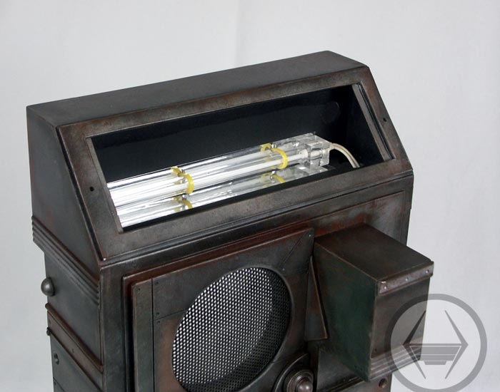
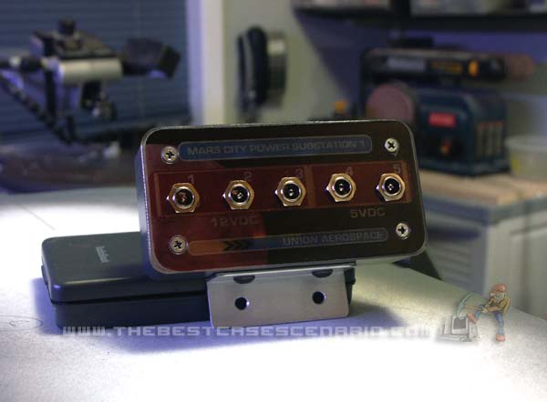
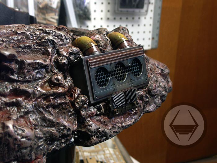
In the first pics you'll see the recessed light fixture I made for the airlock crown piece. This will be an 'always on' light even when the comp is powered down. It's basically a housing, frosted acrylic lens and the LED sockets:

light_fixture-(5).jpg


light_fixture_all.jpg


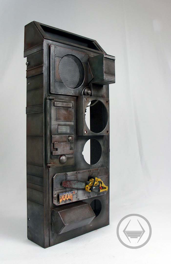
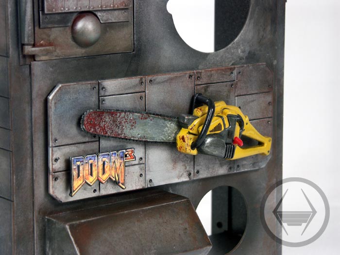
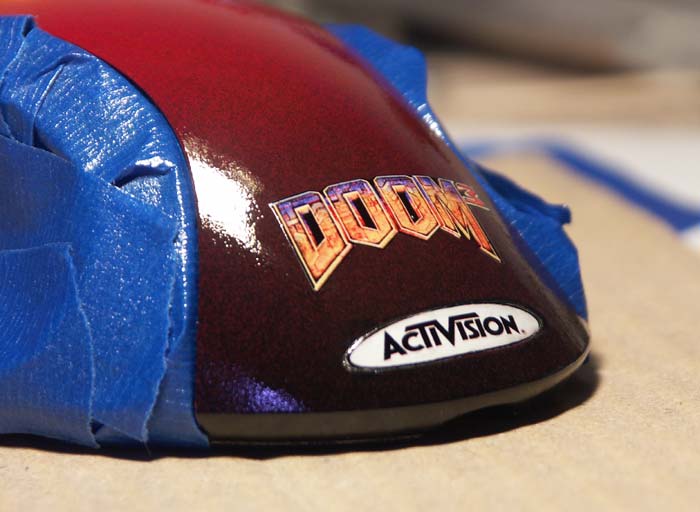
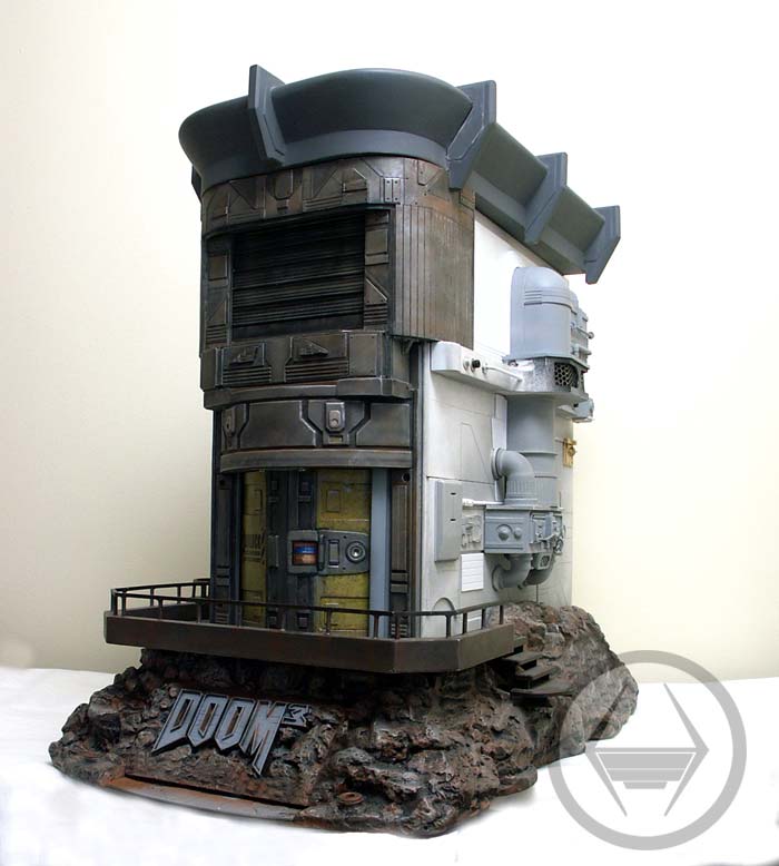
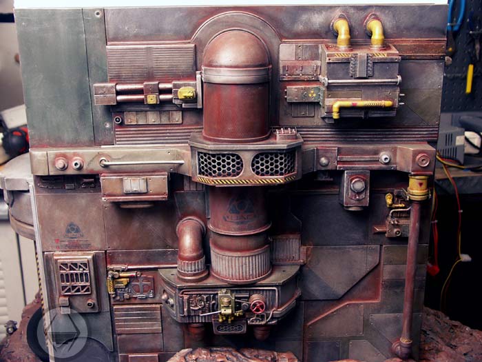
Did some airbrushing as well--the front and all the details are really starting to blend together nicely--this should give a good idea of the patina that the entire case will have:

front_details-(15).jpg


front_details-(1).jpg


front_details-(5).jpg


front_details-(11).jpg


front_details-(9).jpg
 
Well it looks like I'll have to do some more work on this video--so I decided to post the images of the platform that will be featured in it. For anyone interested you'll get a good idea of how to work with styrene plastic.

meanwhile, i completed the platform and all that's left to do is fill some tiny seams and paint it to match my theme. I took a lot of elements from the game such as tread plate, square tubing handrails, a set of stairs on the right side and a small circular landing on the left. I can now place some goodies on the platform such as ammo cases, O2 canisters etc. Here are some pics of interest:

paltform-(16).jpg


paltform-(20).jpg


paltform-(23).jpg


paltform-(26).jpg


paltform-(33).jpg


paltform-(4).jpg


paltform-(7).jpg


paltform-(10).jpg
 
My Santa-wife gave this naughty boy an awesome Doom3 ZBoard--Very cool keyboard to go with my project here...I can't wait to try it out ;)

My very best holiday wishes to every member and visitor here on [H]. Have fun, be safe and love one another. Cheers!


zboard_3.jpg


zboard_2.jpg


zboard_1.jpg
 
Took a break from video production tonigfht and started painting the platform. First a heavy coat of flat black was airbrushed on to fill in all the deep nooks and crannies. next I started adding some layered texture outlines beginning with dark burnt umber. Then came a gunmetal color followed by dark brown. Highlights were then added with a color called "jet exhaust" (for military models obviously) and after that some rust was sprayed on. A well tuned and maintained airbrush is important for this kind of work...so keep those tools clean! :D

All these colors form a base coat that becomes very subtle when the hand painting and color washing begins. It all adds to the depth of scale and color that is needed with mostly metalic architecture. I'll be sure to show the progression of hand painting very soon.

platform_paint-(5).jpg


platform_paint-(b).jpg


platform_paint-(7).jpg
 
Here are a few pics of the scratchbuilt Steam Generator I'm working on at the moment--

The 12v smoke unit has a small fan built in that forces the smoke out of the stack. Well thats not enough for me, so when I build the portion of the feature that connects to the end of the brass pipe, (see below) I'll install a 40mm fan inside to really give the illusion of pressure. Another fan also adds to the volume of smoke that is generated from the unit. This feature at the end of the brass pipe will be a housing of some sort that will have a mesh screen (for letting the steam out, of course!) and red lights inside--I think it will look very Doomish :D

I still have several hours to work on this, kitbashing and scratchbuilding to integrate the whole thing into the side of the case.

steam_unit-(1).jpg


That vent with the mesh on it allows air in for the smoker unit:

steam_unit-(3).jpg


steam_unit-(6).jpg


In this pic you can see the smoker unit:

steam_unit-(11).jpg
 
Here are some pics to give you an idea of how the side panel with the steam unit will look. This scratchbuilt structure was inspired by several screen shots of Mars City building exteriors.

The large main pipe was built as a whole then cut into two sections. You can see here the ribs that form the shape before it is skinned.:

steam_unit_two-(24).jpg


For the round top of the pipe, I formed it into sections and then filled it with Bondo to create the shape:

steam_unit_two-(30).jpg


In this pic you can see the smoke oil fill-tube poking out of the pipe. This fill port will have a removable wheel valve on it eventually, just to mask it.

steam_unit_two-(32).jpg


steam_unit_two-(35).jpg


This vented area is where the "steam" comes out of. With the red LED's in there, it will be pretty slick:

steam_unit_two-(37).jpg


steam_unit_two-(44).jpg
 
I havent had much time to work on the Doom3 case because of commitments to client projects , but I have some previously unreleased pics that i will post in the next few days. ;)

Here is a couple shots of two power distribution boxes I made. These will be painted to match the interior of the case theme basicaly.

disto_boxes-(2).jpg


disto_boxes-(1).jpg


For this one, I made the front plate of the project box out of clear plexi. I then created a simple graphic in PhotoShop and printed it on a transparency. I then epoxied the graphic on the Plexiglas lid and gave the whole thing about 6 coats of clear acrylic spray paint. Two super bright (7000MCD) LED's were hooked up in parallel for interior lighting. You won't be able to actually see this lighted box unless the case is opened, but i wanted to have a little fun making it.:


disto_box2.jpg


Here I placed it in the case just to get a little darkness for the photo:

disto_boxes-(16).jpg
 
It's becoming obvious that the single 120mm rad was not going to be enough cooling for the AMD FX55 and twin 6800 Ultras that will be used for this project--My roof section has now become a cooling tower. The Black Ice XtremeII Radiator should be a better solution for cooling--I may even look into Danger Den's heater core. The PSU will have to be pushed back and outside the case a few inches, but I'll make sure to do some model building and make it blend right back into the case.


doom_chiller-(11).jpg


doom_chiller-(12).jpg
 
IT'S ALIVE!!!

I appreciate everyone being patient while I take care of some other projects---I've been itching to get some work done on D3 myself!

Well here is the latest update...While the airlock was cool...i was pretty much "meh" about the LCD control panel--and I think a few of you out there were as well..so I went and carved out that LCD panel area and installed a tiny light box--with an LED. I then went and made an inkjet transparaency of the airlock LCD from a screen grab--I also enhanced the image with some saturation (since it's the size of a postage stamp!) and sharpening.

I then used a little spray adhesive to mount this inject transparency (there were like 6 images on the sheet in case I screwed up cutting them out) onto a sheet of white paper. After cutting it out, I mounted it on that little plastic light box I made and coated it in 5minute epoxy to create a lens.Here's some pics:

panel_ar-(13).jpg


panel_ar-(3).jpg


panel_ar-(16).jpg


panel_ar-(28).jpg
 
The LCD light is a little bright now that i look at more. --I'll have to tone it down a bit with a beefier resistor. Here are a few pics (long exposure) showing the red status light of the airlock. This will turn to white when the system is powered on and the doors open.

lock_lights-(5).jpg


Hmmm..is this a screenshot from the game-- weird huh?

lock_lights-(8).jpg


lock_lights2(1).jpg
 
You can get decent color fades with rattle cans. Armed with Krylon Fusion paint (which comes in limited but very "Doomish" colors like Burgundy, hot Pepper and black) I gave this Logitech MX1000 laser mouse a simple, easy paint job that I think looks pretty neat. The tail end of the mouse is black, then fades into the burgundy and then into the hot pepper color in front. Once the clear acrylic topcoat is cured, i'll give it a light wetsanding and then some 3M compound and finaly a polishing glaze.

You can work the spray paint on any piece to create a fade, as long as you don't put it on too heavy or work too close to the object. It takes practice, but if you don't have access to an airbrush you should give it a try!|

doom_mouse-(8).jpg


doom_mouse-(11).jpg


doom_mouse-(7).jpg


doom_mouse-(6).jpg
 
I finally have time to finish this monster of a case so lets get to it!

Plenty of details need to be added to the side panels, so I began filling in the sparse areas with some Plastruct architectural pieces and some parts from my scrap bin. I also have a chance now to try out the new Iwata Eclipse airbrush I bought last week. Should be a decent upgrade to the Passche workhorse I have been using for years.


doom3_construction_2-(21).jpg


Small (1/4" NPT) copper elbow was used here:

doom3_construction_2-(24).jpg


This area will take lots of hand painting and airbrushing as you can see. The magic is in the details:

doom3_construction_2-(25).jpg


doom3_construction_2-(27).jpg
 
Adding just the right amount of detail is really important when scratchbuilding and kitbashing on a project like this. It's easy to add too much detail, creating a confusing pallet of shapes that simply adds confusion to the overall look. Picking the right parts for kitbashing comes from lots of trial, error and experience, and literally hundreds of rejected parts and configurations pile up before I commit to gluing them on. Even then I may rip pieces off if it doesn't seem to fit later on as the work progresses.

Tamiya models are among the very best kits you can buy. The detail is amazing, and the quality of their molds are unsurpassed for producing clean, crisp injection molded parts. Although pricey, these kits have been used for kitbashing by master model makers for years--even back to the first Star Wars. If you come across any production shots of the ILM (Industrial Light & Magic)model shop, you'll be sure to find dozens of boxes of Tamiya military kits in the background.

sidepanel_kitbash-(1).jpg


sidepanel_kitbash-(2).jpg


sidepanel_kitbash-(5).jpg


sidepanel_kitbash-(9).jpg
 
I finally found a solution to making the blast doors and airlock open--make linear actuators from old cdrom drives! RC Servos just dont have enough travel in the arms to open the doors I made properly, so by taking the high torque gears and motor that open and close the tray to a CDROM, voila, a linear actuator. I have a short video showing how it works, I'll get it up asap.


Here is a shot of the motor assembly disassembled that will be mounted to that tambour style blast door that covers the LCD on the front of the case:

linear_actuatotor-(1).jpg


This pancake motor is perfect because it is of course, 3-5VDC reversable. It's also designed to last a long time:

linear_actuatotor-(2).jpg


Here is the track assembly. The plastic geared "track" was taken from the CDROM tray and mounted on my aluminum rail:

linear_actuatotor-(14).jpg


The slide assembly has a built-in spring (inside the round alum tube) to prevent the motor from sliding off the geared track when it reaches the ends of the travel. The springs also make sure that the main motor gear is always in contact with the first tooth of the geared track, and ready to move in the opposite direction:

linear_actuatotor-(10).jpg


linear_actuatotor-(9).jpg


linear_actuatotor-(26).jpg


Here is the unit assembled:

linear_actuatotor-(24).jpg


Here is where it will be mounted inside the blast door structure:

linear_actuatotor-(43).jpg


linear_actuatotor-(34).jpg
 
Mechanical airlock? OK!

This nice little challenge is finally complete from a mechanical standpoint. The motors from a CDROM would not be powerful enough to open and close these airlock doors, so the logical replacement would be to use hobby servos. For those of you familliar with these high torque gear boxes, you know some of them pack serious strength--

What I did was create another linear actuator to open and close the doors. Unfortunately the standard servo arms only rotate 45 degrees, and this would not give me enough linear "travel" along the gear bar to open and close my airlock doors. Hmmm..

Solution was to use these specialized servo motors called "retract servos"--these are used to raise and lower the landing gears on flying model aircraft. Not only do they rotate 170 degrees, they also have a higher torque rating than standard servos--perfect for what I need.

You can see I created a "scissor" type mechanism to open and close the airlock doors--sometimes the most elegant solutions are the most basic in design--I had to be extremely accurate with measuring/cutting/drilling in creating this mechanism, and it took some serious tuning to get it running like buttah. The entire mechanism is very robust, so it should last for years without needing adjustments.

I'll have video up ASAP of the door in action!

Enough gab, on with some pics:

You can see that i also made the cut-out for the 120mm Panaflo fan--Airlock opens, fresh air comes in--Here is the airlock module bolted onto the case. I'll be making a housing to cover the scissor mechanism, as well as all the wires for the servo and lighting:

airlock_mech-(12).jpg


Here is the mechanism, top view. All painted and plastic parts (and gears) are lubricated with Lithium grease, as anything petroleum based would eat the plastic:

airlock_mech-(1).jpg


Here you can see the Hitec HS-75BB Retract Servo, and b\gear bar i took from a CDROM tray. The gear on the servo is also taken from the CDROM motor, then it was mounted with tiny screws onto a standard servo wheel:

airlock_mech-(5).jpg


Inside the airlock, I did some kitbashing and scratchbuilding to add details to the back of the doors--Inside will be a light fixture (red LED) as well, pics for that coming up soon:

airlock_mech-(7).jpg
 
Here's a short video showing the motorized airlock in action. The retract servo is controleld by a small single channel servo controller board that runs at 5v DC. The airlock LED light changes to red once it is fully opened and then to white when closed--i may change this to green but i didnt have any on hand.


Airlock Door DivX

Airlock Door Windows media
 
Here is a shot showing the case mocked up thus far--Just a bit of scratchbuilding, wiring, watercooling, lighting and hardware installation left to do--and of course--some airbrushing and hand painting :)

doom_mod_side1.jpg
 
The power block simply makes putting this complex mod together much easier. It gives me a break point in the power line so the case itself can be removed from the rocky base that holds the SATA CDROM and harddisk..

doom_paint_finish-(14).jpg


These dual 60mm fans help cool off the Fujitsu 15kRPM drive.
doom_paint_finish-(15).jpg


Here is the exhaust fan for the base unit.

doom_paint_finish-(16).jpg
 
I decided to do away with many of the mechanical switches and buttons on the mod and go for solid state with an IR remote control--because how cool is RC??-- :D I picked up a 12 Channel IR Relay Board (in kit form) and assembled it in about 2 hours. The nice thing about this board is that you can have an on/off configuration on the channels or momentary switching, or a combination of both. To test it out I hooked it up to the blast door module--works like a charm.

remote_relay-(2).jpg


remote_relay-(7).jpg


remote_relay.jpg


Here is the air intake vent for the HDD cooling fans. This scratchbuilt piece uses some styrene sheet, modder's mesh and two copper plumbing elbows. To get the subtle shading in the paint, first it was airbrushed, then hand detailed and finaly a soft shading with Doc Browns' weathering powders applied with a sable brush. This is pretty much how I painted the entire mod.

intake-(6).jpg


intake-(19).jpg


intake-(21).jpg


intake-(13).jpg


intake.jpg
 
Whew!...alright it looks like its finally in the home stretch--Nothing more to build, just paint and assemble--easier said than done--although since the entire mod is built around modules, everything should fit right into place. Lots of wiring to do as well--but its 99% done overall. Here are some pics from last weeks build:

Etched pentagram window in its frame with LED lighting. Basically its 6 ultrabright red lamps wired in parallel:

window_lit-(6).jpg


window_lit-(8).jpg


Here is the roof module during painting. The cover caps off the roof nicely and includes 2x 120mm fan vents for the Black Ice pro radiator.

roof_cooler-(3).jpg


roof_cooler-(5).jpg


Here you can see that i curved the interior of the roof module to allow for airflow off the radiator:

roof_cooler-(9).jpg


The Antec case is really small for a mid-tower, so I built an extension for the rear of the case. This allows me to push the PC Power & Cooling 510 SLi PSU out the back about two inches, giving me preciuous room inside for wire managment and components. The round holes on the extension piece are for PSU fan exhaust, an 80mm fan and a hole for the water pump. This estension piece also conceals all the typical messy wires on the back of the PC :

rear_extension-(1).jpg


There is even a hinged door for access to the I/O panel of the motherboard.

rear_extension-(4).jpg


Once its all painted up and weathered, I'll take individual pics of all the components before assembly to show all the parts.
 
Revisiting that extension piece I made for the back of the case, here it is finish painted. I made a little plaque that has the Doom3 logo and the chainsaw that I made way back at the start of the project. There is also a spot for a lighted marquee (where you see the 4" white CCFL) at the top of this extension piece, and this will have a backlit transparency that has a bit of the project's history printed on it.


rear_extension_whole.jpg


rear_extension_detail_1.jpg


rear_extension_marquee.jpg
 
Status
Not open for further replies.
Back
Top