DOOM 3: Project Mars City Mod

Status
Not open for further replies.

CrimsonSky

Gawd
Joined
Jun 14, 2003
Messages
711
I would like to thank all the great people here at [H] who have been helping with this project from its first few pages. From the incredible laser etched pentacle window that was made for it to the terrific suggestions and postings from all who have been watching. I don't have a timeline to completion for this project, so be patient ;) Big thanks to the tireless [H] leader and all the mods.-cheers

-Crim
thebestcasescenario.com
A mirror of this worklog can be found here:
http://www.thebestcasescenario.com/forum

**NEW** Photographic Inventory of (almost) every single part and PC component of the project. This album will be updated regularly

Also, check outMy New Modding Book, a must have for case modding begginers and advanced craftspeople!


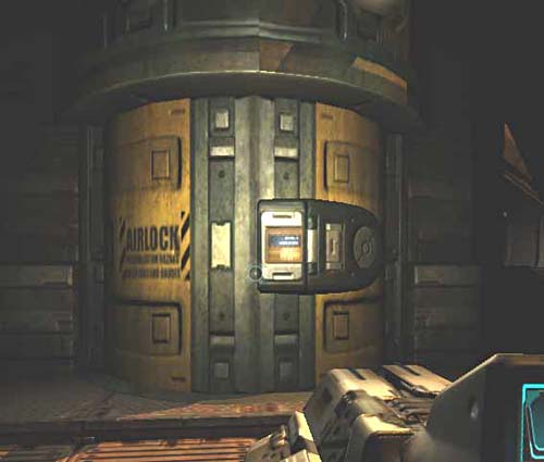
There will no doubt be a bunch of Doom3 casemod themes this year and next, so I thought I'd add my project to the mix. Project Mars City will be fun to build with lots of kitbashing for that military/industrial Doom3 look. Expect lots of armor, mesh, lighted machinery, pressure doors, plumbing, and maybe a few sculpted animatronic beasties.

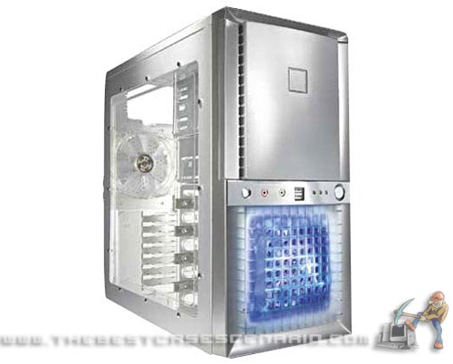
This case will be a Doom3 gaming MONSTER, DangerDen watercooled, and top of-the-line hardware and components that have yet to be determined. I have an Antec Super Lanboy to use as a base, since it's very lightweight, and the kitbashing/structural enhancements will add enough strength to this otherwise flimsy case.


Since Mashie and I are both working on Doom3 inspired cases, we set up a Live ModCam so anyone interested can see the projects as they progress. Please no complaints if the cameras aren't up 24/7--we are working on getting a dedicated server. Live ModCam

bg_antec05.jpg


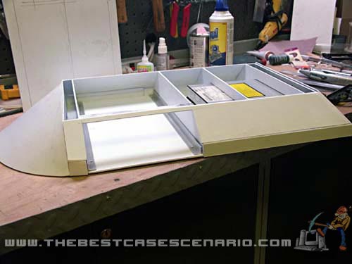
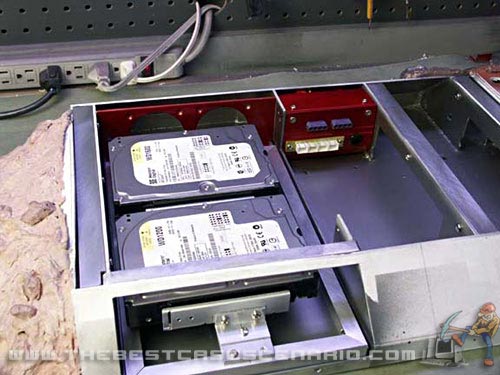
I'm making a base unit for that Antec case, with Mars terrain--i.e rocks and craters--it will also house the optical drive. I need to free up the 5.25 drive bays for the video monitor that will be integrated--probably a Xenarc, earthlcd or equivalent.

Here is the start of the base that will have a Martian terrain look. It will also house the optical drive and a few other goodies :D

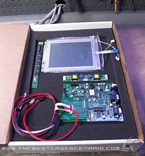
I found a motorized 7" LCD screen meant for in-dash applications. The LCD is a Panasonic OEM, so it should be pretty good. Anyone know of other brands I should look into?.

http://www.mp3playerstore.com/stuff_you_need/special/TM-7300.htm

base_1.jpg

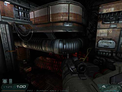
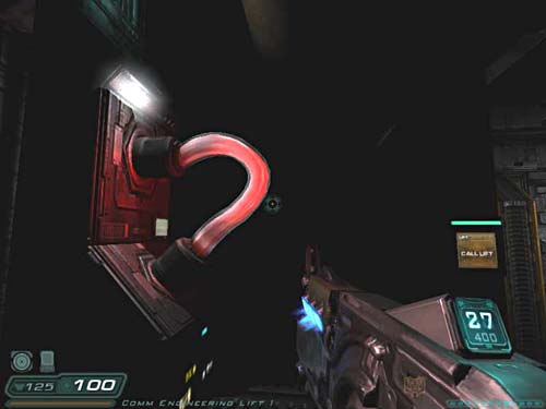
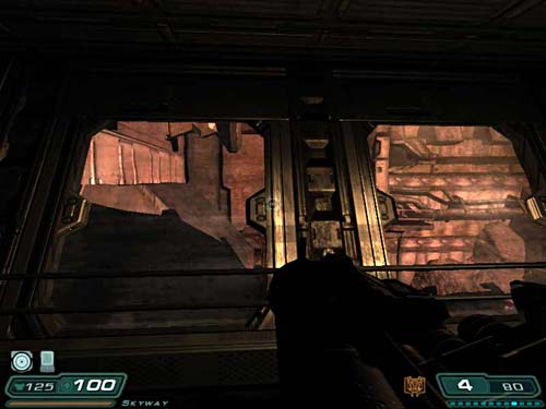
After speaking with a friend today who was kind enough to spend some time and give great ideas, i took some screenshots for inspiration. Mr. Nervous lead me in the direction of a 3/8" hose watercooling setup, so I will go with DangerDen blocks and pump for the system. There will be lots of elements from the game as far as look and feel, plus some imagination thrown in. There are so many directions a mod like this can take, but after speaking with D he thought the case itself would be cool if represented as one of the building installations on Mars, with a few water cooling parts outside the case and then slithering their way inside.

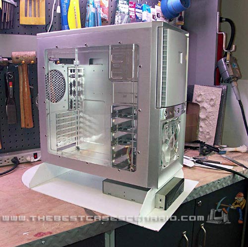
The Antec case at this point is just a shell, having popped most of the rivets and drive cages offm and will hardly be recognized once completed.

Any ideas are welcomed, this should be lots of fun to join in on! :D


shot00002.jpg


shot00017.jpg


shot00031.jpg


shot00028.jpg
 
As an Amazon Associate, HardForum may earn from qualifying purchases.
The Antec Super Lanboy is pretty flimsy---think soda can. What I did here is took the panel from the motherboard side and swaped it. I then cut a third off from the panel and mounted an aluminum bar on each side--it gave it lots of rigidity. Then I installed two utility hinges. The smaller section will be permanently mounted while the other side opens for accesability. Now I can mount parts to the smaller section (like the res for instance) permanently. This was Dick's idea--and a good one.

The hinges will be hidden eventually with kitbashed and scratch-built model parts.

doom_struct_2.jpg


doom_struct_1.jpg


Here is a shot of the half cone shaped section i completed last recently.

dm_assemble_2-(2).jpg


This section with aluminum rails will have a slide out tray with a MediKit box for cookies and snacks ?

dm_assemble_2-(3).jpg


Martian landscape material. I'll use this sheet as a mold for making resin sections on the base.

dm_assemble_2-(6).jpg


I got a few various sized rubber rock molds for Martian terrain. These are used to create boulders and rocks for model train landscapes, but in this case will be for Martian terrain :D

I mixed up some bondo and spread it on the mold with a stick like you would frosting. about 90 seconds later I pulled them from the mold:

dm_assemble_3-(6).jpg
 
Well after working about 10 hours I just about finished the base. This will be covered in Martian terrain, with a little of it on the case itself to blend in.


dm_assemble_4-(11).jpg


dm_assemble_4-(13).jpg


dm_assemble_4-(3).jpg


dm_assemble_4.jpg


Before I can cover the rest of the base with Mars terrain, I have to get the bottom part of the case finished, so I can blend it in. The case itself will become a structure modeled after the buildings in the game.

shot00069.jpg


shot00070.jpg


Here I started to create the scribed panels that will cover the case. On top of this will be various parts from model kits. Lots of pipes and small details as well. I penciled out some lines on the plastic panels, and using a scribing tool I cut the grooves you see here:

dm_assemble_6-(3).jpg


dm_assemble_6.jpg


the many hours of kitbashing has started--I scrounged some parts from various model kits, but it looks like I'll have to go buy some more at the hobby shop.

dm_assemble_7-(3).jpg
 
Created a window on the building that will give a peek (albeit dusty) view into the interior of the case. The window will be slightly angled off the face of the building, like a bay window. I also added rivets to the scribed panels for even greater detail.

dm_assemble_8-(1).jpg


dm_assemble_8-(4).jpg
 
The sound board arrived today--yay! It has a LOT of features Some of them are:

*9-15v power input

*8ohm speaker ready with amplifier. Can also be plugged into PC sound card via mini plug.

*RS-232 Interface for controling 9 channels of sounds via simple ASCII commands from your PC

* 6 channels of audio that can be recorded (4 minutes total) individually, and played simultaneously or one at a time. You can use momentary switches, IR triggers, just about any switch. Sound is recorded on-the-fly from any output source using a 1/8" min plug. There is no soldering at all required with this board.

Will have lots of Doom3 sounds recorded into it for various features on the case, like doors opening. Also plenty of beastly monster sounds and voices. This board is avaialable at Blue Point Engineering

snd_board.jpg
 
Mashie had a great idea for my airlock door, and kicked it up a notch with a challenge to make it servo operated. When the system powers up, the airlock opens just like in the game (complete with sound effects) to reveal the radiator and allow air inside the case :D

In this pic you see the housing I completed for the door. Next step is to make both doors and rig the mechanics, and of course model the details.

The housing will actually be partway inside the case, just propped up there for the picture.

dm_assemble_9-(5).jpg


dm_assemble_9-(7).jpg


Well the structure for the airlock is complete. The only [H]urdle yet to jump with Mashie's challange is to connect the servo mechanism and apply the relay hack to the pcb board that controls them. The servo will be cable operated using a simple scissor type mechanism. The Black Ice 2 Xtreme radiator will be mounted on the back of the airlock, with the 120mm fan inside. Before all this is done I'll decorate the door with all the little details found in the Doom3 screenshot.

dm_assemble_10-(5).jpg


dm_assemble_10-(8).jpg


dm_assemble_10-(1).jpg


dm_assemble_10-(13).jpg


shot00094.jpg
 
The detail on the airlock is completed--after a couple hours straining the eyes. A rough coat of primer helps me see the detail as I progress. All these details were cut with an X-acto knife from styrene plastic sheet (same material as all the panels on the mod ) and glued on with super glue. The control panel touch screen on the airlock will be a decal that I make in photoshop. The fun part of this project will be painting--I have over 20 different colors of paint that will be airbrushed and handpainted on the mod. :D

dm_airlock-(2).jpg


dm_airlock-(1).jpg


What better way to test out the 30 jars of Model Master paint I purchased yesterday than to do a little finishing on the airlock--A combination of airbrushing and hand painting. Once I settle on a color for the Martian dust I'll be blending in that color onto the structures. The panel monitor is a printout with a glaze of clear 5-minute epoxy. I purchased a "Do-it-yourself inkjet" decal making system for the lettering on the opposite door, should arrive next week. What it does is create on your printer clear and very thin decals, the same that comes with model cars and other kits. Hopefully it will be a quality product--keep you posted.

dm_airlock_2-(b).jpg


dm_airlock_2-(5).jpg
 
For the top of the case, I chose to make the same rounded "crown" type moulding you see on the exterior buildings in the game. First I had to frame out the shape by cutting the joists from plastic on the scrollsaw. Next step is to put the "skin" on the joists to create that moulding's shape around the case. I'm thinking of putting another feature on top, maybe the "Communications" tower, with small windows all around it, perhaps an oscilating dish---who knows. What i really want to do is use this space to put a small animatronic creature that busts out of the building: head going side to side and arms reaching out and grabbing...just the head, shoulders and arms--haunted house style :D

dm_crown-(4).jpg


dm_crown-(7).jpg


The moulding is now just about complete. The joists were "skinned" and acrylic half-round rod was heat bent and put in place. The next step is to do a little mud job with Bondo to fill the seams and even out the round corners.

dm_crown2-(9).jpg


dm_crown2-(3).jpg
 
small update, but its taking many hours to get just right. The top of the building was smoothed out with Bondo and shaped. After wet sanding a coat of primer was given to see how its shaping up. Working now in the vertical support pieces. Each one is 5 layers of plastic sheetglued together, then carved and shaped.

dm_crown3-(1).jpg


dm_crown3-(5).jpg


Qtip42 said:
Crim, I like the bondo job you did but you think that's sturdy? Bondo cracks easily :D

With the framing i did its extremely strong-I took a pic while standing on it--so there is 180lbs right on the bondo parts--mind you I wouldnt do this if I thought 6 hours of work would be even slightly cracked or ruined :p

built_tough.jpg
 
Before I can close up the window housing, I needed to add some detail behind the glass, giving another layer of interesting little pipes, machinery and gadgets. I also need to install the lighting effects in this window "box" as well. This stuff is tedious as hell, I cant wait to get onto hardware and water cooling :D

While kitbashing:

window_bezel_2.jpg


Gray laquer primer sprayed on:

window_bezel_1.jpg


Window box mock-up:

window_mockup.jpg


After a bit of paint applied:

window_frame-(12).jpg
 
We all make mistakes, and on the first Airlock label I SPELLED HAZARD WRONG with two z's..I've been making that same spelling mistake for 25 years now..pretty funny that i posted it wrong. here it is fixed up:

door_decal-(5).jpg


door_decal-(4).jpg
 
This sad pentagram I made was later replaced by design by cgrant26 and laser etched by DeathLok30040. You can see their efforts below ;)

Created a pattern for an etched pentagram that will live behind the small window on the side. Once I have it etched I'll light it and do a mockup on the case.

The 1/4" plexi piece was first covered in blue masking tape. After that a printout of the pentagram was applied using spray mount adhesive. With an Xacto blade I scored the pattern down to the plexi, and then removed the protective layers. I coat of flat black paint was sprayed on as a guide for etching, then all the paper/masking tape was removed.

pent_window.jpg


With a carbide bit I started removing the paint and etching the surface. The X-acto blade created a nice channel in the plexi for the bit to follow along in. Once etching is complete, I'll polish the edges of the plexi, mount the window and install lighting.

pent_etch-(3).jpg


Once the etching was complete, I polished the edges of the plexi in preperation for the 4" CCFL lights. One red, one yellow will light the edges. I'll use the same automotive CCFL's I used for Metropolis . They are really bright and the colors are true.


Here is the etching in the window box you've seen before. There are two panes of glass, one in front and one behind, with the etching:

window_etch_2-(3).jpg


here is a cheesy photochop enhancment:

window_etch_2-(1).jpg
 
Since the airlock is not just for show, a lot of thought had to go into mounting it. I decided to build the airlock and Black Ice Extreme 2 120mm radiator into a unit that could be removed easily, hence the thumb screws. The unit also had to be pretty solid to keep the airlock doors in good alignment.

btw before anyone asks (like a certain other modder) the interior will be painted to match elements in the game :p

cooling_unit-(12).jpg


cooling_unit-(28).jpg


cooling_unit-(17).jpg


cooling_unit-(25).jpg
 
I was going to have a Chainsaw fangrill cut from aluminum--however I was persuaded to make a reproduction from the game. I will use this gunsight grill as a base (with crosshairs removed) for it. The grill will be on the 120mm fan inside the airlock, which will be lit with several LED's. I might make a silicon mold of this grill when complete, so I can reproduce them and sell 'em. :D


I will model the chainsaw in plastic sheets to create layers until it is built up. Then I'll carve and shape. Here you see just the motor and handle assembly

chainsaw_grill-(1).jpg


chainsaw_grill-(5).jpg


Layer by layer, the chainsaw takes shape. and Yes..it will have a bloody blade :p ;)


chainsaw_grill2-(7).jpg


Got this part done, all is needed is the second handle, saftey brake, pull start handle and saw blade :D

chainsaw_grill3-(4).jpg


A little blade action:

chainsaw_grill5-(6).jpg


I'll hack off the gunsight befor mounting:

chainsaw_grill5-(2).jpg


Chainsaw goodness:

The chainsaw WONT be mounted on the ring in that drastic of an angle--it doesnt look right. it will be mounted at about 15 degree angle at the center.

dm_grilltest1.jpg


dm_grilltest2.jpg
 
Having fun and experimenting with a little Doom style lighting. This is one red and one white "lazer" type lighting fixture:


lighting_test-(4).jpg
 
It's time to get the rest of the base covered in Martian terrain--but before I can do that, I have to create the stealthed-out bezel for the optical drive that is on the front of the base.

On the bezel will be none other than the Doom3 logo, faithfully recreated in styrene sheet plastic, painted and airbrushed complete with metal plating like the original. the logo will be "pillow embosed" into the Martian surface, and when the optical drive button is pressed it will travel with the tray.

here is the front of the case where the logo is going:

logo_area.jpg


here is the logo, as if we all don't know it by now
doom3_logo.jpg


D is for DOOM!!- :D Here is the first letter:

3D_logo_1-(7).jpg


3D_logo_1-(4).jpg
 
Got the second letter complete: Do the DO :p

3D_logo_2-(3).jpg


Here you can see how they were constructed. They are indeed hollow.

3D_logo_2-(6).jpg
 
A few of you have requested a "how to" for the logo I made--here it is :cool:


The first step was to print out a Doom3 logo to the scale I wanted for the case mod. Next I carefully cut the letters out one at a time with a very sharp X-Acto bladeto use as a template.

letters_howto2-(2).jpg


The paper template was then mounted to thin styrene plastic sheet using spray mount adhesive:

letters_howto1-(1).jpg


The plastic was then carefully cut along the template:

letters_howto1-(2).jpg


The paper template was then removed:

letters_howto1-(5).jpg


Next I used a mechanical pencil to draw in the signature Doom3 metal plating:

letters_howto1-(6).jpg


With a scoring tool, I then lightly scored the plastic along the pencil lines:

letters_howto1-(10).jpg


letters_howto1-(12).jpg


To build up the sides of the letter, I cut strips of plastic, cut them to size one at a time and glued them to the letter. I use Flash brand super glue, and a "kicker" or accelerator that makes the super glue dry instantly when sprayed on.

letters_howto1-(21).jpg


The letter was lightly sanded and then given a few coats of laquer based, micro-filling primer made by Alclad.

letters_howto1-(26).jpg


here you have the primed letter, ready to mount and airbrush ;) Lastly, I'll do the "3" and finish this all up.

letters_howto1-(29).jpg
 
I got around to casting some rocks for the Martian landscape--then applied a little basecoat of paint. From images of Mars, looks to me like plenty of rusted soil and blackish/gray rocks poking out. Here I imagined bedrock, what the building would have been built on-...sort of an outcrop of blasted and machine cut stone. The sides of the base will be smoother terrain. You can also see the Doom3 logo, which is now part the optical drive bezel. I'll have small spotlights illuminating the bottom half of the logo eventually


terrain_test-(4).jpg


terrain_test-(13).jpg


The white strip you see under the door is a temporary spacer until the bezel is mounted
terrain_test-(11).jpg


terrain_test-(17).jpg
 
I got around to shimming up the door, aligning it and so forth--I mounted the bezel on an old CDROm just to test it and rigged up a button. here is a 5second video:

Door Open/Close
 
I'm Baaaaack!!!

I finaly opened the box containing the XLK-5002T 6.5" Analog Color TFT LCD Kit from www.earthlcd.com. As you can see..I'll have to build a housing of some sort to mount the parts in. Parts include 6.5" LCD, Resistive Touch Screen Panel, inverter for the two backlights, controller card and cables.

This LCD will be mounted in the 5.25" bay area above the airlock, possibly behind a door that has the UAC logo emblazoned on it. This LCD will run off of a secondary graphics card and have an gui to launch apps, videos and scenes from the game, or monitor the webcam that will be part of the mod...I guess there's lots of fun stuff to use it for!

earthlcd_1.jpg
 
Now that the base unit will house the two hard disks and CDROM, I needed to get power into it. I made a distribution block that has two male Molex connectors and four 3-pin fan connectors. The fan connectors are for the two 60mm fans that will be in the base, as well as for lighting the Doom3 logo on the CD bezel.

The block is made from aluminum stock and a cut piece of extruded aluminum door threshold, then painted with DupliColr red annodized-look paint. No one will ever see this power block, but I still like to finish "what isnt seen" ;) Once it's dry and assembled I'll post pics:

power_block_1-(2).jpg


power_block_cut.jpg
 
This should help clear a few things up :D

The base unit will now house the CDROM, as well as the two hard disk drives. The drives are on a removable frame that locks in place once it is slid into the base. I also made a fan frame to hold the two 60mm intake fans. Ports on the bottom odf the base will vent the air.

base_unit_1-(3).jpg


base_unit_1-(4).jpg


Here you can see the simple locking mechanism for the HDD frame. The frame slides on this, locks into place under the lip and is secured on the opposite end by two screws.

base_unit_1-(6).jpg


base_unit_1.jpg
 
In the first pic you see the base unit and the new top that the case will sit on. The top is 0.40 styrene reinforced with fiberglass cloth and resin. The oval shaped opening on the side is the intake for the HDD cooling fans, and will have a special grill made for it eventually.

d3_base_terrain-(13).jpg


In this pic, I'm in the process of adding more Mars terrain made from rubber mold castings and applying it to the side. It's really time consuming task to get it looking natural. You can see that the rock has a horizontal grain, to look like cut bedrock. Once all the rocks and stones are carved and glued in place, I go back and blend them all in. Then a few hours work with a Dremel and carbide bit to add small carved detail.

d3_base_terrain-(23).jpg


And here are the main parts in place:

d3_base_terrain-(22).jpg
 
I decided to put a plate steel walkway around 3 sides of the building, and Mashie thought it a good idea to raise it up from the terrain. I'll mount the walkway now on aluminum columns planted in the ground, level with the airlock. Will have some ammo here and there on the walkway as well. This detail should look really cool when done ;)

walkway_2.jpg


walkway_1.jpg
 
well i FINALLY finished the terrain--I'll take pics when its prime painted. Meanwhile I hooked up a single red Lazer LED to that killer window and snapped a few shots---I'll adjust the color to more orange by adding a yellow Lazer unit and a second red:

window_test-(2).jpg


window_test-(1).jpg


window_test-(4).jpg
 
The terraforming operations are basically complete on the base.My next step is to integrate 2 rocks with hidden LEDs to light up the lower half of the Doom3 logo with amber light.

terrain_complete-(4).jpg


The white oval section you see is a rough opening for the HDD fan vent. It will not be oval once the grill is modeled into it. I'm thinking two fat vent pipes that go up the side of the building.

terrain_complete-(11).jpg


terrain_complete-(5).jpg


Here you see the section removed for access to the inside of the base:

terrain_complete-(13).jpg


terrain_complete-(24).jpg


terrain_complete-(27).jpg


terrain_complete-(41).jpg
 
I decided to make two miniature spotlights that will be mounted on the base to illuminate the Doom 3 logo. These little babies will be mounted in the rocky area on either side of the logo and pointed towards the lower half. Completely adjustable as well =)

spotlight_1-(4).jpg


Here is a spotlight broken down:

Its made from an aluminum tire valve cap, a piece of aluminum U channel, steel rod, rubber grommet, aluminum tubing various screws and a 2-pin fan connector as a socket for the LED.

spotlight_1-(9).jpg
 
I think with a little tweaking this lighting for the logo will be really sweet. Here are a couple early pics, remember that nothing is painted yet:

light_test-(1).jpg


light_test-(3).jpg
 
Added a little snoot to each light...Seems to focus it better...I like it!...Just about all I can do with it considering the angle of the mounted fixtures. The logo will really pop even more once painted..

light_test2-(3).jpg


light_test2-(1).jpg
 
Some of you have been waiting to see how the touch screen LCD from www.earthlcd.com will be mounted--well here it is!--I started constructing the architectural piece that will house the LCD unit---complete with motorized blast/storm door.

Here is the part during framing. You can see the curved channels that the blast door will ride on when the button is pressed:

blast_door-(14).jpg


The LCD during test fitting:

blast_door-(19).jpg


Here's where it's mounted:

blast_door-(10).jpg


I printed a door on a piece of paper just to give an idea:

blast_door-(24).jpg


blast_door-(30).jpg


Now you see I've started to "skin" the framed piece:

blast_door2-(2).jpg


More to come soon!
 
The housing for the LCD touch screen is now more of a module--removable from the case with just a few screws. Much better than mounting the various parts of the LCD inside the case where you cant get to them---we all like easy access to the inside of the case for tweaking and fixing what isnt broke right ? :D

Here is the unit, I'll explain pic-by-pic. This first shot is were i left it for the night, having created the various mounting plates, brackets and what-not to hold the screens in place. The control panel for the LCD was just a pcb with a single LED and 5 little tactile buttons (power, menu, navigation etc). The buttons wont be visible on the mod, but hidden behimd a panel:

LCD_1-(5).jpg


You can see here the small clear acrylic hemispheres I glued onto the microswitches.

LCD_1-(7).jpg


Inside the unit, the housing will hold all the LCD parts (see below) as well as the servo and electronics for operating the blast door.:

LCD_1-(10).jpg


This is the LCD hold-down plate (in white) and control button hardware:

LCD_1-(19).jpg


The inside starts to get a bit more complicated:

LCD_1-(22).jpg


The parts for the earth LCD (www.earthlcd.com) kit. Controller board, LCD panel, Touch screen (made from glass), function button pcb and the power brick for the two CCFL's:

LCD_1-(26).jpg
 
Powered up the LCD screen to see if i could fry something :p The LCD image is stunning--very crisp--and the colors are sharp and vivid. I couldnt get the touch screen to work on the serial port--will have to call their tech support since there is no documentation with this kit :confused:

lcd_power-(6).jpg


lcd_power-(1).jpg


The obligatory [H]ard shot:

lcd_power-(10).jpg
 
WHEW!! Ok all the basic engineering and construction on the LCD module/motorized blast door is finally complete. I've completed the roll up door and integrated all the parts of the LCD kit. The next step is to finish up the airbrushing/hand painting and mount the servo unit to operate the blast door.

here is the roll up blast door. It was constructed in segments, with each segment having its own bolt-type hinge, so its very flexible. The bolts are small steel rod inside plastic tubing, with a hing plate. there are 24 hinges in all. Each hinge can fit inside of a dime--so its pretty small. It operates similar to a store-front security gate:

lcd_module_finishing-(12).jpg


Here you can see how flexible it is. Each segment had to be slightly smaller than the radius of the blast door tracks that it rides on.:

lcd_module_finishing-(15).jpg


The door is inserted from the bottom of the track:

lcd_module_finishing-temp.jpg


Here is the door in place. It still needs fine tuning and adjustment, but that will happen when the servo is installed:

lcd_module_finishing-(25).jpg


lcd_module_finishing-(26).jpg


Once the parts of the LCD kit are mounted in place, you will get a sense of the how this design works from a structural standpoint:

lcd_module_finishing-(34).jpg


The section that holds the control panel for the LCD now has a hinged door to hide it:

lcd_module_finishing-(8).jpg


lcd_module_finishing-(10).jpg


Here i'm adding a detail strip to the top of the module. Details were scribed and cut from plastic and then mounted to the strip (in white) The strip is then glued to the top of the module. Creating a detail strip firt makes it easier to add small detail, rather than gluing them directly to the larger module itself. Also if ya screw up, you wont have to scrap glue off of a finished part :

lcd_module_finishing-(41).jpg


Clamped in place for final test fit:

lcd_module_finishing-(46).jpg


Then finally glued in place, and airbrushing is started:

lcd_module_finishing-(53).jpg


lcd_module_finishing-(49).jpg


More to come soon!
 
Took a break from construction tonight and enjoyed some airbrushing. There is still a degree of weathering i have to do on it, and some drybrushing with silver to expose worn metal. Here is a mock-up of what i have so far:

lcd_module_paint-(7).jpg


lcd_module_paint-(3).jpg


The best way to hide a hinge is..you guessed it...with another hinge! I needed access to a mounting screw so i made this little flap:

lcd_module_paint-(13).jpg


lcd_module_paint-(15).jpg
 
I could NOT get the touch screen to work--i will have to call tech support on Monday :confused: :mad:

here is the UI in it's current state of development. The resolution is incredible, the color amazing--Lothar you'd love it. When the app opens, we get a video sequence of our Mars City hero in action:

lcd_test_2-(5).jpg


Then he stops to open his PDA, and the interface begins--its really an awesome, clean transition--but was too quick for me to capture on camera:

lcd_test_2-(9).jpg


lcd_test_2-(8).jpg


The UI is now up. with icons on the left, they bring up applications, vwebcams, web pages audio files, video files, credits. You can also restart the opening sequence. very nice:

lcd_test_2-(1).jpg


lcd_test_2-(10).jpg


lcd_test_2-(16).jpg
 
What may not seem like a big update on this project actually took a tremendous ammount of work on my part--in between dealing with other projects/clients I managed to create the final piece that finishes off the front of the case--the molding above and around the airlock door. The design is pulled from the game with a few added touches to make it blend in with the LCD module that lives above it.

This scratchbuilt part had to fit nice and snug with the airlock while allowing it to open smoothly, so many hours of measuring and cutting the styrene sheets was needed to get a tight seam. The decorative panels that were laminated onto it made it so strong that when knocked on it sounds like knuckles on a football helmet--yeesh..very strong indeed.

Once this section is airbrushed and blended in with the rest of the front, it will start to come together. I'll put all the parts together tomorrow and post a pic of the entire case. You'll also notice that i started painting the Martian terrain. I'm waiting on a few bottles of paint before i add the final touches by hand and airbrush.


airlock_crown-(7).jpg


airlock_crown-(2).jpg


airlock_crown-(14).jpg


airlock_crown-(18).jpg


airlock_crown-(23).jpg
 
Status
Not open for further replies.
Back
Top