• Some users have recently had their accounts hijacked. It seems that the now defunct EVGA forums might have compromised your password there and seems many are using the same PW here. We would suggest you UPDATE YOUR PASSWORD and TURN ON 2FA for your account here to further secure it. None of the compromised accounts had 2FA turned on.
    Once you have enabled 2FA, your account will be updated soon to show a badge, letting other members know that you use 2FA to protect your account. This should be beneficial for everyone that uses FSFT.

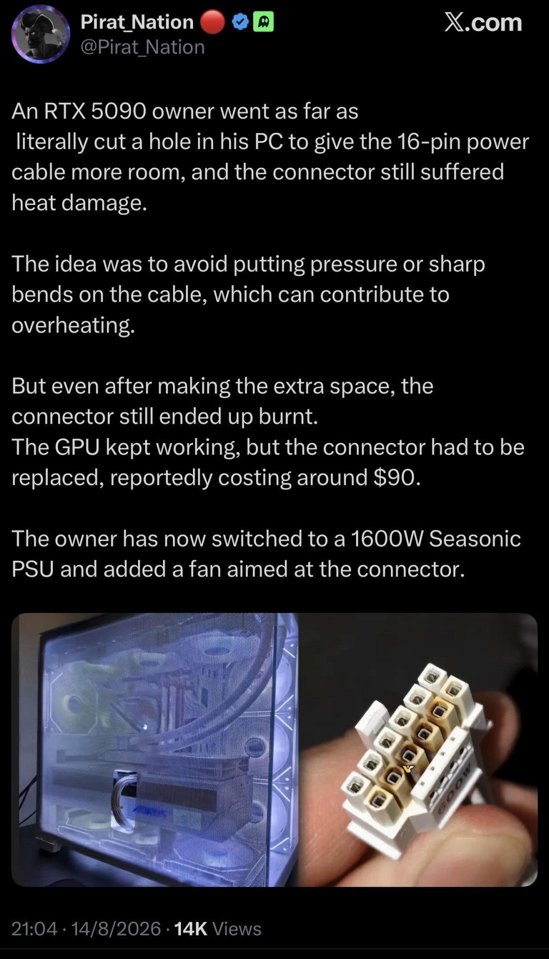
RTX 5090 FE Molten 12VHPWR

At some point even members of this forum have to admit that the issue is users not plugging the connector in correctly. I still have faith that a PC enthusiast forum will eventually see reason, but the world in general is making me think my faith is misplaced.

Article says, "the cable was fully seated at both ends and had no sharp bends" and then proceeds to provide a picture where the connector is not fully seated.

View attachment 814679

At some point you’ll have to admit that the load balancing on this connector sucks and redlining it, like anything else, is a bad idea. This has been measured and verified as problematic by engineers using ammeters. This isn’t all on user error. It is in some cases, not in all. There are relatively inexpensive solutions that can be implemented to help protect from catastrophic failure. PSU companies wouldn’t be working on and marketing fixes for a problem that doesn’t exist.
 
At some point even members of this forum have to admit that the issue is users not plugging the connector in correctly. I still have faith that a PC enthusiast forum will eventually see reason, but the world in general is making me think my faith is misplaced.

Article says, "the cable was fully seated at both ends and had no sharp bends" and then proceeds to provide a picture where the connector is not fully seated.

View attachment 814679
The implementation fails basic standard electrical wiring standards. nVidia does not need to be defended for saving pennies on thousand dollar GPUs.
 
The implementation fails basic standard electrical wiring standards. nVidia does not need to be defended for saving pennies on thousand dollar GPUs.
The problem is only going to get worse, GPU power demand is going up not down. They are going to have to design a better connector with per pin load balancing.
 
The problem is only going to get worse, GPU power demand is going up not down. They are going to have to design a better connector with per pin load balancing.

The biggest problem is that this connector is designed for datacenters, not for home PC use. Datacenter cooling is significantly better than your typical case, and spacing for the cables is set up in a way that doesn’t required you to bend the cable as aggressively. Crap load balancing compounds all of these problems, but the datacenter environment, which you don’t have in your typical case, neutralizes at least some of the problem. Nvidia likely won’t make any changes unless the datacenter guys complain.
 
The biggest problem is that this connector is designed for datacenters, not for home PC use. Datacenter cooling is significantly better than your typical case, and spacing for the cables is set up in a way that doesn’t required you to bend the cable as aggressively. Crap load balancing compounds all of these problems, but the datacenter environment, which you don’t have in your typical case, neutralizes at least some of the problem. Nvidia likely won’t make any changes unless the datacenter guys complain.
The 12V-2x6 connector itself wasn't specifically designed for data centers. It was developed by the PCI-SIG and was standardized in PCIe CEM 5.1. More cooling wouldn't specifically help in this particular case anyway, the problem is in how much power goes through a particular conductor. The only thing they could do (without changing the connector or the power supply end) is increase the gauge of the wires for more current carrying capability by say 2x (or whatever was truly necessary) so that even if only 8 of the 16 wires are actually transferring power you would still have a margin of error, it wouldn't get as hot.
 
The 12V-2x6 connector itself wasn't specifically designed for data centers. It was developed by the PCI-SIG and was standardized in PCIe CEM 5.1. More cooling wouldn't specifically help in this particular case anyway, the problem is in how much power goes through a particular conductor. The only thing they could do (without changing the connector or the power supply end) is increase the gauge of the wires for more current carrying capability by say 2x (or whatever was truly necessary) so that even if only 8 of the 16 wires are actually transferring power you would still have a margin of error, it wouldn't get as hot.
The crazy thing is only 6 wires carry current. The other 6 are ground, and the smaller 4 pins are sense (via ground?) pins.

I finally broke down a few weeks back and bought a Thermal Grizzly WireView Pro II. Good thing I did, because two of my pins were wildly different. One around 6.5A, the other around 10.5A (the spec is 9.1A max per pin). And I know what the fuck I'm doing... These connectors are planned obsolescence, pure and simple.
 
The implementation fails basic standard electrical wiring standards. nVidia does not need to be defended for saving pennies on thousand dollar GPUs.
I don't think the design was about saving money, but space. Both having less cables, and having a smaller connector area on the board, allowing the board to be smaller, which allows for more unobstructed heatsink area. In particular servers (which are nVidia's big market) is where this is a big deal. Having 4 8-pin PCIe connectors trying to run to a card would be a nightmare, and then you take a server that has 8 cards in it... Man. In fact even before this you already saw differences. The connectors used for PCIe 8-pin are actually rated for 300 watts, not 150. That gives less safety margin, of course, but servers used them like that. You'd see 8-pin connectors that ran a full 300 watts over them. Desktop PSUs have been doing it too, but in servers it was a bigger deal because of space.

I don't hate the idea. I really don't like running a ton of cables to me GPU and 4x cables is getting stupid. Likewise, the incidence of melting really does seem to be less than people scream about. Heck let's look at this forum: There's quite a few 4090 and 5090 owners here. Should we do a poll to see how many have had a melted connector? HOWEVER it does need improvement. It is pushing things too hard. Personally I'm in favor of something that is 2x8 pin, same 600w limit. That pushes the safety margin up quite a bit and adds only a small amount of additional cabling and space. That combined with higher thermal requirements on materials would probably do the trick.

Long term? It might be time to talk about going to higher DC voltage inside PCs. I mean basically everything these days does their own power conversion using a DC-DC converter. Your GPU doesn't run on 12v internally, neither does your CPU. It takes the 12v and converts it down to what it needs real near the chip. No reason that couldn't be done with a higher voltage and if you increase the voltage, you drop the amperage, and thus heat, needed for a given amount of power. Might be time to look at a 24v or 48v GPU connector for power supplies.

Heck, USB did this for power delivery. The new PD standard was increased to 240w to accommodate higher draw systems, including slim gaming laptops. Thing is, they didn't want to change the connector or make a chonkier cable, which would be required to up the amperage past the 5 amps that the first PD standard allowed. So instead they increased the voltage from 20v to 48v. Might be time to make (another) a new GPU connector that has higher voltage.
 
The 12V-2x6 connector itself wasn't specifically designed for data centers. It was developed by the PCI-SIG and was standardized in PCIe CEM 5.1. More cooling wouldn't specifically help in this particular case anyway, the problem is in how much power goes through a particular conductor. The only thing they could do (without changing the connector or the power supply end) is increase the gauge of the wires for more current carrying capability by say 2x (or whatever was truly necessary) so that even if only 8 of the 16 wires are actually transferring power you would still have a margin of error, it wouldn't get as hot.

Fair, but it's certainly performed better in the datacenter space due to the factors I've mentioned, and I'm sure that was the primary point of consideration when the design was created. For regular users, it's a bad design. I don't understand why Nvidia's so pig-headed about their board partners not offering an 8-pin option, but perhaps it's because they know the customer will just shell out for another Nvidia card when their current one self-immolates.
 
The 12V-2x6 connector itself wasn't specifically designed for data centers. It was developed by the PCI-SIG and was standardized in PCIe CEM 5.1. More cooling wouldn't specifically help in this particular case anyway, the problem is in how much power goes through a particular conductor. The only thing they could do (without changing the connector or the power supply end) is increase the gauge of the wires for more current carrying capability by say 2x (or whatever was truly necessary) so that even if only 8 of the 16 wires are actually transferring power you would still have a margin of error, it wouldn't get as hot.
A larger wire gauge does little to help the localized heating caused by connector pins not designed to handle the amount of current they're experiencing. The primary problem are the pins. Wires are a distant second. Actually, the primary problem is the common bus, which then cascades into the pin problem.
The crazy thing is only 6 wires carry current. The other 6 are ground, and the smaller 4 pins are sense (via ground?) pins.

I finally broke down a few weeks back and bought a Thermal Grizzly WireView Pro II. Good thing I did, because two of my pins were wildly different. One around 6.5A, the other around 10.5A (the spec is 9.1A max per pin). And I know what the fuck I'm doing... These connectors are planned obsolescence, pure and simple.
Technically the only wires not carrying current are the 4 small sense wires. The ground is carrying current- away from the card as opposed to towards the card on the +12v lines. Technically electrons travel from negative to positive but we generally treat current as flowing from positive to negative. The ground wires are at risk of failing like the positive wires because they are carrying just as much current. Well, maybe less if the connector ground is also tied to the PCI-E bus ground.
I don't think the design was about saving money, but space. Both having less cables, and having a smaller connector area on the board, allowing the board to be smaller, which allows for more unobstructed heatsink area. In particular servers (which are nVidia's big market) is where this is a big deal. Having 4 8-pin PCIe connectors trying to run to a card would be a nightmare, and then you take a server that has 8 cards in it... Man. In fact even before this you already saw differences. The connectors used for PCIe 8-pin are actually rated for 300 watts, not 150. That gives less safety margin, of course, but servers used them like that. You'd see 8-pin connectors that ran a full 300 watts over them. Desktop PSUs have been doing it too, but in servers it was a bigger deal because of space.

I don't hate the idea. I really don't like running a ton of cables to me GPU and 4x cables is getting stupid. Likewise, the incidence of melting really does seem to be less than people scream about. Heck let's look at this forum: There's quite a few 4090 and 5090 owners here. Should we do a poll to see how many have had a melted connector? HOWEVER it does need improvement. It is pushing things too hard. Personally I'm in favor of something that is 2x8 pin, same 600w limit. That pushes the safety margin up quite a bit and adds only a small amount of additional cabling and space. That combined with higher thermal requirements on materials would probably do the trick.

Long term? It might be time to talk about going to higher DC voltage inside PCs. I mean basically everything these days does their own power conversion using a DC-DC converter. Your GPU doesn't run on 12v internally, neither does your CPU. It takes the 12v and converts it down to what it needs real near the chip. No reason that couldn't be done with a higher voltage and if you increase the voltage, you drop the amperage, and thus heat, needed for a given amount of power. Might be time to look at a 24v or 48v GPU connector for power supplies.

Heck, USB did this for power delivery. The new PD standard was increased to 240w to accommodate higher draw systems, including slim gaming laptops. Thing is, they didn't want to change the connector or make a chonkier cable, which would be required to up the amperage past the 5 amps that the first PD standard allowed. So instead they increased the voltage from 20v to 48v. Might be time to make (another) a new GPU connector that has higher voltage.
The only explanation for the common bus is to save money. Fewer traces = money saved. PCI-E connectors were not tied to a common bus- they were prohibited from doing so. Even the 3xxx series 12vhpwr had sets of pins separated that each powered their own parts of the board. It makes no sense to run each pin to the limit and have them all tied together on the board instead of each one providing power to its own set of VRMs.
 
Cheap way to ensure if a pin or two fails or is degraded is to fuse each wire, when one pin resistance goes up causing increase current to the other power pins, the fuses will blow one after another, all would fail protecting the Card and Power Supply. Then again this is just another fail point, resistance point. The connector, newest version is designed, if not plugged in all the way the card will not work. Cannot be user error not plugging it in all the way since it would never draw any significant current. The spec is too close to the failure point, that is what makes it a very poor design combined with normal cable bends that can affect the pins performance plus no secondary safety measures as in current sensing or even temperature sensing shutdowns.
 
The only explanation for the common bus is to save money. Fewer traces = money saved. PCI-E connectors were not tied to a common bus- they were prohibited from doing so. Even the 3xxx series 12vhpwr had sets of pins separated that each powered their own parts of the board. It makes no sense to run each pin to the limit and have them all tied together on the board instead of each one providing power to its own set of VRMs.
I dunno, you telling me you think they did it just to save money on $15,000 datacenter GPUs? Like I can, maybe, get it for consumer GPUs though even there I kinda doubt it given all the other high-cost things you see on them, and their overall high price. However it is the same setup on the datacenter Blackwell GPUs. I mean I guess it could be different on the board, but I can find no evidence it is.

I really feel like this was what they claim it was: An engineering choice related to space and density. You can argue that it isn't needed on home GPUs, but I can see why they did it.
 
A melted connector, and next, a melting hotspot?

1783937510350.jpeg
 
...

Technically the only wires not carrying current are the 4 small sense wires. The ground is carrying current- away from the card as opposed to towards the card on the +12v lines. Technically electrons travel from negative to positive but we generally treat current as flowing from positive to negative. The ground wires are at risk of failing like the positive wires because they are carrying just as much current. Well, maybe less if the connector ground is also tied to the PCI-E bus ground.

...
Of all the burned 12 pin connectors that I've seen on reddit, only the positive pins have been burned. And most common were the ones on the ends. In my case, the imbalanced pins were pin 2 (low amperage) and pin 6 (out of spec high amperage), and a new adapter solved it... for now.

It's a shitty connector that isn't designed to last.
 
I dunno, you telling me you think they did it just to save money on $15,000 datacenter GPUs? Like I can, maybe, get it for consumer GPUs though even there I kinda doubt it given all the other high-cost things you see on them, and their overall high price. However it is the same setup on the datacenter Blackwell GPUs. I mean I guess it could be different on the board, but I can find no evidence it is.

I really feel like this was what they claim it was: An engineering choice related to space and density. You can argue that it isn't needed on home GPUs, but I can see why they did it.
Absolutely. There is no technical reason why they couldn't have each pin feed its own set of VRMs, which would solve the load balancing issue. It wouldn't solve the fact that each pin is being run close to the limit, but melted connectors would be far less likely to occur with separated pins because the design won't allow any pin to go over its rated current unless power limits are removed. It would cost more in manufacturing and engineering because there will be more small traces and engineers would have to decide how many VRMs get put on each pin.
 
What do you mean by "older model"? 12V 2x6 is on connector end only. Cable remains the same.

As for this ModDIY cable, I agree with others that the design is poor for this cable type allowing each individual wire to get strained and looking more closer its a shame how twisted up the user had it. One wonders if they'd have had the melting with a first party 12VHPWR cable instead.

So is the prevailing theory that the contacts are not making good-enough contact between the female and male ends, which can cause micro-arcing which of course creates plasma which plastic tends to turn to goo around.......or was it the cards just trying to push too much current through too-tiny wires. This is DC power so those wires WILL heat up like in any DC system if thermals of your wires were maybe not on your radar.

its sort of like when people think their breaker box will save their $2500 OLED during an electrical storm....no, doesn't work that way, breakers protect your wires in your house...not you, and not your stuff. This looks to me like a problem that gets solved using thicker gauge wire.......or thicker-gauge connectors.....
 
So is the prevailing theory that the contacts are not making good-enough contact between the female and male ends, which can cause micro-arcing which of course creates plasma which plastic tends to turn to goo around.......or was it the cards just trying to push too much current through too-tiny wires. This is DC power so those wires WILL heat up like in any DC system if thermals of your wires were maybe not on your radar.

its sort of like when people think their breaker box will save their $2500 OLED during an electrical storm....no, doesn't work that way, breakers protect your wires in your house...not you, and not your stuff. This looks to me like a problem that gets solved using thicker gauge wire.......or thicker-gauge connectors.....
Can't make the connectors thicker- they're at their physical limits. Wiring can be thicker but they're not the core of the problem.
 
So is the prevailing theory that the contacts are not making good-enough contact between the female and male ends, which can cause micro-arcing which of course creates plasma which plastic tends to turn to goo around.......or was it the cards just trying to push too much current through too-tiny wires. This is DC power so those wires WILL heat up like in any DC system if thermals of your wires were maybe not on your radar.

its sort of like when people think their breaker box will save their $2500 OLED during an electrical storm....no, doesn't work that way, breakers protect your wires in your house...not you, and not your stuff. This looks to me like a problem that gets solved using thicker gauge wire.......or thicker-gauge connectors.....
From what I understand from other people's research (DerBauer, Gamers Nexus primarily), it's mostly the bad pin mating creating increased resistance/heat and then it snowballs from there. A much larger pin size could help to fix this problem, but would necessitate a larger connector... which was the primary reason for the smaller connector: saving PCB space and money for Nvidia and the other companies (AMD, Intel, etc.) that signed off on this standard via PCI-SIG.
 
Can't make the connectors thicker- they're at their physical limits. Wiring can be thicker but they're not the core of the problem
I assumed the core of the problem was going to be trying to push sustained loads of 500 watts+ through these tiny
wires and connectors, what is that 12 gauge wire they are using for power delivery? I mean it sounds like Nvidia
wants to solve a hardware problem with a software fix...
 
I assumed the core of the problem was going to be trying to push sustained loads of 500 watts+ through these tiny
wires and connectors, what is that 12 gauge wire they are using for power delivery? I mean it sounds like Nvidia
wants to solve a hardware problem with a software fix...
There are even reports of 9070XTs with melted 12+4 pin connectors, so it's not purely the amount of power going through the wires.
 
There are even reports of 9070XTs with melted 12+4 pin connectors, so it's not purely the amount of power going through the wires.
Correct, it is a load balancing problem coupled with tiny connection medium that doesn't press hard enough to handle over spec amp loads. PCIe 8 pin had a safety factor of 1.8 [meaning it could handle almost double what it was rated at], the 12v 2x6 has a safety factor of 1.2.
 
I wonder if using a single 10 or 12 AWG stranded wire plus a single return wire and maybe some sense wires would be a better solution because a single heavier gauge wire and a solid way to connect it snugly is all you need instead of a wide 12v 2x6 connector. Sure, two larger wires would be less elegant looking, but you could eliminate all the tiny connections and focus on a larger connection surface such as a blade style connection with tighter contact patch instead of barrel style connections which tend to have more friction but doesn't necessarily translate into better connection for electricity.
 
I wonder if using a single 10 or 12 AWG stranded wire plus a single return wire and maybe some sense wires would be a better solution because a single heavier gauge wire and a solid way to connect it snugly is all you need instead of a wide 12v 2x6 connector. Sure, two larger wires would be less elegant looking, but you could eliminate all the tiny connections and focus on a larger connection surface such as a blade style connection with tighter contact patch instead of barrel style connections which tend to have more friction but doesn't necessarily translate into better connection for electricity.

Than you run into larger bend radius on thicker wires and maybe not fitting the case as well which won't fit the requirement. Or you then have to do 90 deg connectors to fit the case and that might block something else. Bend radius on wiring has been one of the more painful aspects of my job over the last 30 years.
 
Than you run into larger bend radius on thicker wires and maybe not fitting the case as well which won't fit the requirement. Or you then have to do 90 deg connectors to fit the case and that might block something else. Bend radius on wiring has been one of the more painful aspects of my job over the last 30 years.
12 AWG stranded or the fine battery wire type strands, is not hard to bend. Heavier wire will handle bending better than light gauge wire. I work in the cellular industry where I have had to deal with battery wire, radio wiring, etc for DC current applications.
 
Last edited:
I'm not an EE and have no knowledge of the functional limits of PCB traces, but would doubling the voltage to reduce amperage increase the safety margin of the contact points? Or would that then introduce complexity on the GPU board that would result in increased failures as well?

Obviously that's a compatibility breaking change to ATX spec and you'd want Yet Another New Connector so someone doesn't fry a GPU with double the expected voltage in an upgrade/replacement scenario.
 
I'm not an EE and have no knowledge of the functional limits of PCB traces, but would doubling the voltage to reduce amperage increase the safety margin of the contact points? Or would that then introduce complexity on the GPU board that would result in increased failures as well?

Obviously that's a compatibility breaking change to ATX spec and you'd want Yet Another New Connector so someone doesn't fry a GPU with double the expected voltage in an upgrade/replacement scenario.
It would be possible to double the voltage to 24 volts DC and then adjust the power managing components to support that change, but then you have the issue of another voltage that needs to be produced by PSU, a separate, special connector for +24 VDC, so it would get complicated quickly. They really need to design a better connection medium than 12 tiny barrels.
 
It would be possible to double the voltage to 24 volts DC and then adjust the power managing components to support that change, but then you have the issue of another voltage that needs to be produced by PSU, a separate, special connector for +24 VDC, so it would get complicated quickly. They really need to design a better connection medium than 12 tiny barrels.
None of that is particularly complicated. The new connector, well we already have that. Internally PSUs already do DC-DC conversion for all the different rails, adding one more voltage wouldn't be a big deal, or all that much more cost.

The reason it isn't done is COMPATIBILITY. If they made a 24v (or 48v) GPU you'd have to get a new PSU. There'd be none of this "janky multi-cable adapter" stuff, you'd need a new PSU. That would hurt sales quite a bit. So they stick with 12v.

If it happens, it'll probably happen in servers first.
 
None of that is particularly complicated. The new connector, well we already have that. Internally PSUs already do DC-DC conversion for all the different rails, adding one more voltage wouldn't be a big deal, or all that much more cost.

The reason it isn't done is COMPATIBILITY. If they made a 24v (or 48v) GPU you'd have to get a new PSU. There'd be none of this "janky multi-cable adapter" stuff, you'd need a new PSU. That would hurt sales quite a bit. So they stick with 12v.

If it happens, it'll probably happen in servers first.
If you look closely, they’ve already forced us to buy 3.0/3.1 PSU blocks for “better” compatibility with 12VHPWR. And I don’t see any reason why they couldn’t do it again...

*And when I think about it, the 3000/6000 series had a problem with high peak power levels, and the solution was... a new PSU.
 
If you look closely, they’ve already forced us to buy 3.0/3.1 PSU blocks for “better” compatibility with 12VHPWR. And I don’t see any reason why they couldn’t do it again...

*And when I think about it, the 3000/6000 series had a problem with high peak power levels, and the solution was... a new PSU.
I mean there's a difference between something where there's a more compatible setup and where you NEED a new setup. I do not have an ATX 3.0 PSU yet it has run a 3090, 4090 and now 5090 just fine. It's a Seasonic Prime Titanium 1000w. It's a well designed PSU that has had no issues with the transients of the 3090, and has a very nice 1st party cable to go from 2x 300w 8-pin connectors on the PSU to a 12vhwpr on the GPU.

However if the GPU was 24v or 48v, well then nothing doing, I'd have to get a new PSU. I mean in theory you could make an adapter box that does the DC-DC conversion... but that is really just a DC PSU and the cost would be non-trivial enough to make just getting a new PSU worthwhile.

Now please don't misunderstand, I'm an advocate of this. I think it is time to move to higher voltage and not just for the PSU. I think it would be good for motherboards too, and it makes the possibility of running high power traces through he board, or through cables wired in the case a lot more possible. However it is a big compatibility break. In the past with new standards because they were all still 12v, you could just use adapters for quite awhile. Like when PCIe power came out, you could just connect multiple molex connectors and use them to power it. Eventually that became non-feasible, like you couldn't realistically have enough of them to power a 3x 8-pin PCIe card, but the old PSUs didn't become useless for a long time and generally just naturally aged out. Same kind of deal with 12vhpwr. I have no need to replace my PSU because of it, it'll keep working with new cards that use it despite not having a native port.

A voltage change breaks all that, and now you HAVE to get a new PSU with the new components. Makes it a harder sell. We've seen the same shit in cars for a long time. Because of the much more power hungry modern car there has long been talk about moving cars to a higher voltage, but it hasn't happened and compatibility is the reason. EVERYTHING car is 12v, and if a new car is 48v, well then nothing works with it. You need a different alternator, different battery, different accessories, etc. Nobody has wanted to take the jump, despite the fact that it would make a lot of sense to do so. Instead we the thicc as fuck wires and 250a-400a alternators.

The one other thing I DON'T know is if there'd be any issues with components needing to do a larger voltage conversion. I don't think so, but maybe. Since CPUs and GPUs generally run on a volt or less these days perhaps it would be more of an issue to convert from 48v to 1v than from 12v to 1v. Again, I don't believe so, but I don't have near enough EE knowledge to state that with confidence.


As I said: If we see it, I'm pretty sure it will be servers first. You'd see it in special high-performance GPU servers that are purpose built, then maybe in other more general high end servers and once it got established there maybe the consumer market would jump. Probably be systems like Dell Optiplexes, which use custom PSUs anyhow, that do it first before there's a new ATX standard and something that enthusiasts use.
 
12 AWG stranded or the fine battery wire type strands, is not hard to bend. Heavier wire will handle bending better than light gauge wire. I work in the cellular industry where I have had to deal with battery wire, radio wiring, etc for DC current applications.

All things being equal, thicker means a bigger bend radius. Yes, if you change the wire type when you go bigger then you might salvage the bend radius.
 
Back
Top