DarkenReaper57
2[H]4U
- Joined
- Oct 2, 2003
- Messages
- 2,173
Hey, I'm kinda a noob to electronics. I've been doing a lot of reading, but more complicated things like IC's in a circuit are still rather overwhelming.
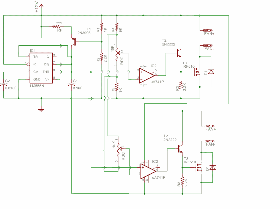
Anyway, I want to build this PWM circuit here: http://casemods.pointofnoreturn.org/pwm/circuit3.html.
Now, I'm also a noob to matching electronic parts (specifically IC's). I wanna try to get everything locally at radioshack if possible since shipping usually kills any decent buys online.
Is this the same as the uA741P op-amp as described in the guide? http://www.radioshack.com/product.asp?catalog_name=CTLG&product_id=276-007. If not, why and where can I find out?
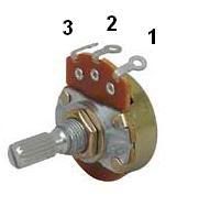
Oh, another thing - I would like to modify the circuit so I can use 2 or 3 total pots to regulate different fans. How would I go about doing this? Would I need to use one IC for each pot?
Thanks.
EDIT: Is there also anything at radioshack that will work instead of a 2n222 transistor? I can't seem to find that one...
Anyway, I want to build this PWM circuit here: http://casemods.pointofnoreturn.org/pwm/circuit3.html.
Now, I'm also a noob to matching electronic parts (specifically IC's). I wanna try to get everything locally at radioshack if possible since shipping usually kills any decent buys online.
Is this the same as the uA741P op-amp as described in the guide? http://www.radioshack.com/product.asp?catalog_name=CTLG&product_id=276-007. If not, why and where can I find out?
Oh, another thing - I would like to modify the circuit so I can use 2 or 3 total pots to regulate different fans. How would I go about doing this? Would I need to use one IC for each pot?
Thanks.
EDIT: Is there also anything at radioshack that will work instead of a 2n222 transistor? I can't seem to find that one...

") .
.