I've been visiting the site for a while. I'm an active member on another site and thought it was time I joined here. I come often for the reviews, so it's time I engage in the forums. Many of you have really incredible builds. This isn't as huge, but I tried to give the best quality possible for my budget and time constraints. These entries have been copied from a thread on another forum. I hope you enjoy! Also check out my previous iteration here.
5/30/2006

This is my worklog of my Nintendo Entertainment System turned to an PC. This is actually a rebuild of the one I've already posted on here. I'm hoping to clean it up a bit and I am forgoing the gaming idea. It's really hard to make it a gaming PC and not cost effective. Instead this will be a media center and rom machine.
That being said this case will have no new holes to the outside. No holes for mobo outputs or anything. I will use existing holes to do a similar/same job as the component in that place did before.
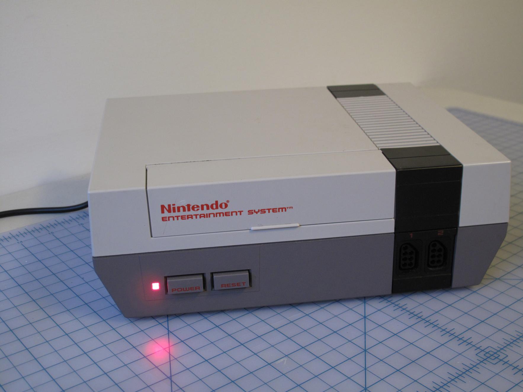
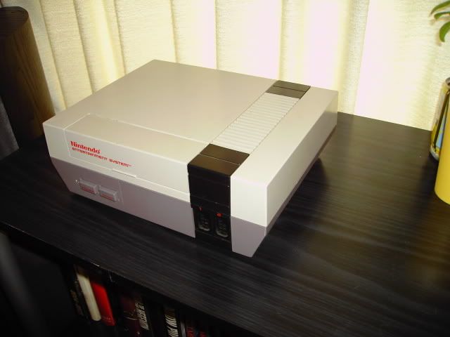
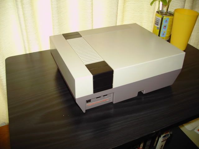
Here is the case. It needs to be cleaned up a bit, but that is always bset done near the end, right before final construction so that it doesn't get dirty while modding.
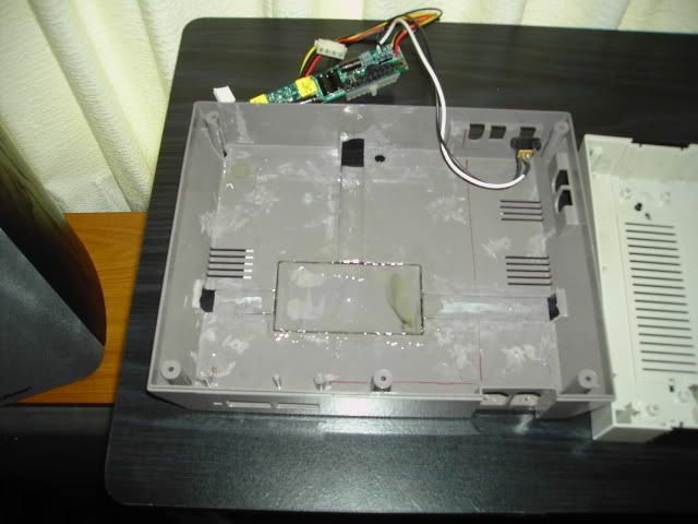
Here is the inside. I've already cut out the "T" and epoxied the remaining plastic back on the bottom. It needs to be sanded still, but being at school with no tools I may have to hold that for a while and work on another part.
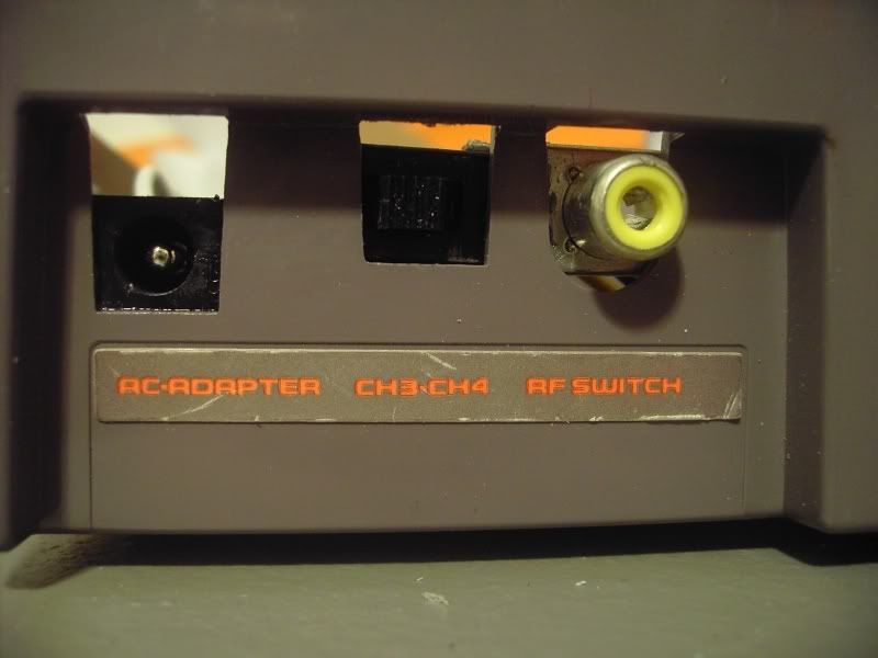
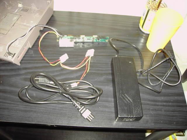
Here is a power supply pic. I got this at mini-box.com. It is an incredible 200 watts in that strip. (They also sell an incredible 120W pico PSU that everyone should seen.) I've already glued it into the case where it says "AC-ADAPTER" and it looks perfect.
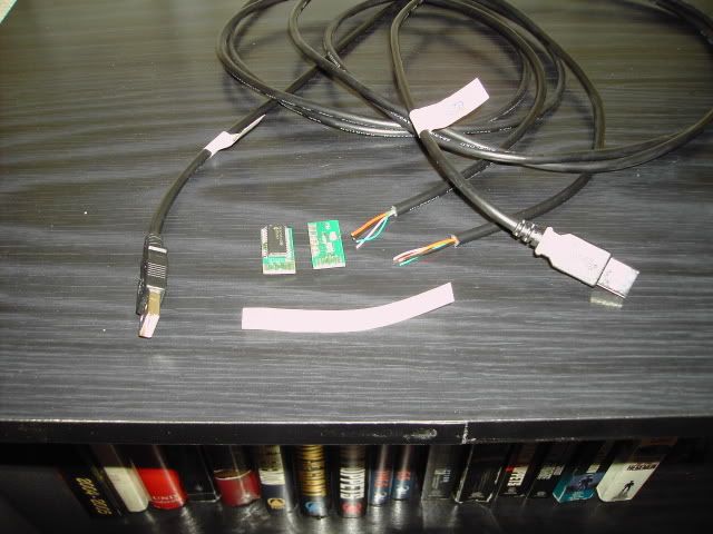
This is what I got when I ordered two NES kits from retrousb.com for $17 each. For each kit you get a tiny chip and a six foot USB cord. For comparison, Nintendo controllers had a seven foot cord. The little paper that you can't read in the pic says,
"NES RetroKit wiring diagram at:
http://www.retrousb.com/retrokit.html"
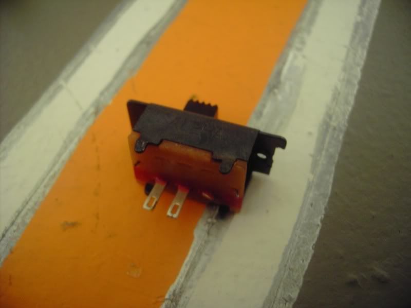
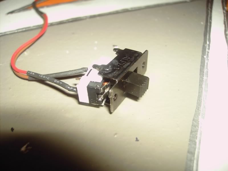
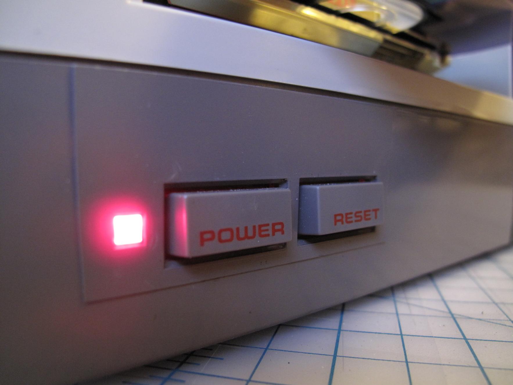
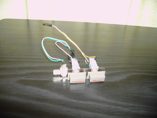
Here are the modded power and reset buttons. I got these thin and easily solderable buttons here.
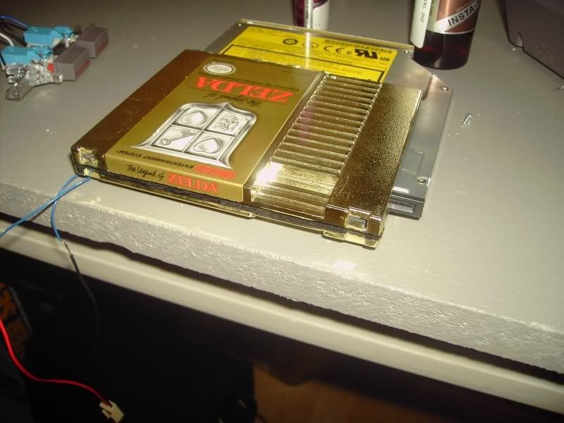
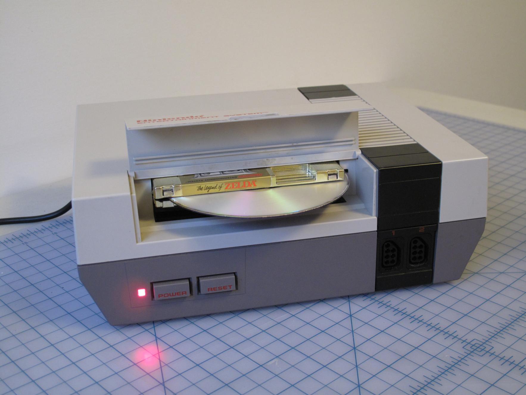
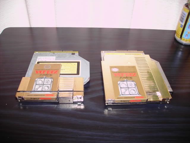
Here are my DVDs drives. The one on the left is the one I had in my old NES PC and is just a combo drive with no burning capabilities. The one on the right is a Panasonic UJ-845-B. Here are the stats: DVD-RAM 5x, DVD-R 8X, DVD-RW 4X, CD-R 24X, CD-RW 16X. Both are modded with DEAD Zelda carts. I am not a murderer.
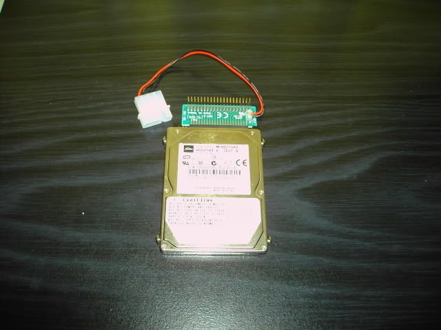
Here's my real basic Toshiba 60Gb laptop HD.
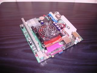
Here's the mobo. It's a mini-atx form factor, Commel LV-670 board. I have a 1.8Ghz P4 in it and a 1Gb stick of cheap gigaram DDR. The cooler is a pretty cool copper cooler for 1U servers. It says that it is rated to 2.8Ghz, but I doubt it.
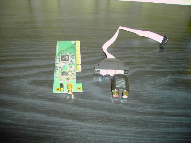
Here is a cheapo 802.11 b/g PCI card and a jumper/header for audio. The header has a stereo A/V converter so it can go out to a TV since that is my goal to have this look stock and function like an old NES.
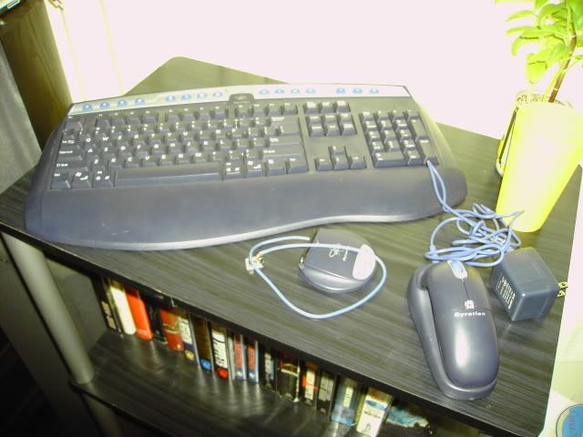
Here is the Gyration wireless keyboard and mouse combo. The USB reciever has been rewired to be really short and to fit inside the NES since I don't want anything coming out of the finished product. The only problem is that I rewired it backwards (doh!) so I'll have to do it again. [On a side note Nintendo went to Gyration to have them make the gyros in their new Wii controlers]
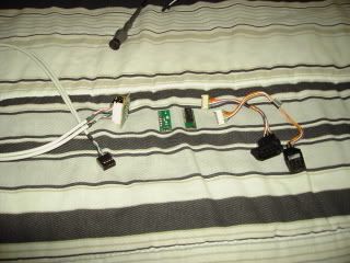
This pic has a USB jumper for the mobo. This jumper can be unplugged from a small PCB that has the female USB part on it. I am hoping to use this USB jumper 'molex' type connector and disconnect it from the PCB and then resoldering/wiring that to the retrokit chips. The chips would also be soldered/wired to the 'molex' connector that leads to the NES female controller ports. This way I could just unplug a few cords when I want to work on something inside the PC and have easy access.
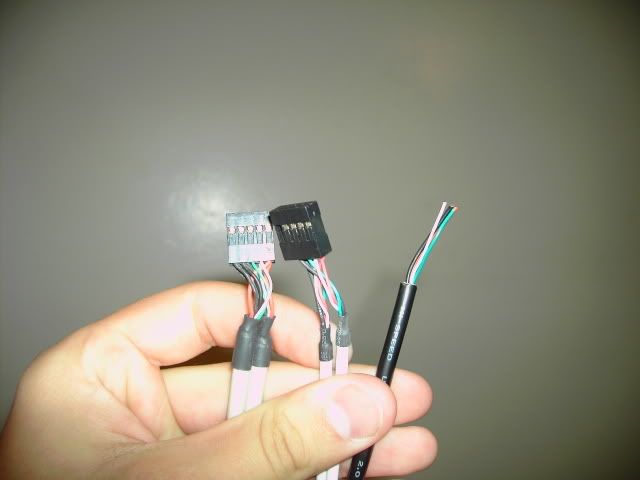
Last pic has a question attached to it. On the left we see the USB mobo jumper that came with the mobo. In the middle we see an extra jumper that I have and would like to use. On the right is the USB cable that came with the retrokit for the controllers. The one I want to use has a little bit of plastic guarding it from being plugged in the USB jumper place on the mobo. The one on the left has more black wires than the middle one I want to use, but the USB cable that came with the kit has only one black wire. Here's the question: Is it okay if I just pull out the little plastic guard and use the jumper I want anyways for the controller kit? What do the extra black wires do? They are just extra ground, right?
I am going to be constructing an inner box for all the parts that can be removed when I want to work/change something on the PC. I have 2mm sheet styrene and it will be perfect. Give me your oppinions and ideas.
6/1/2006
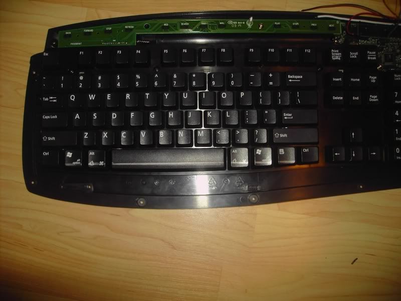
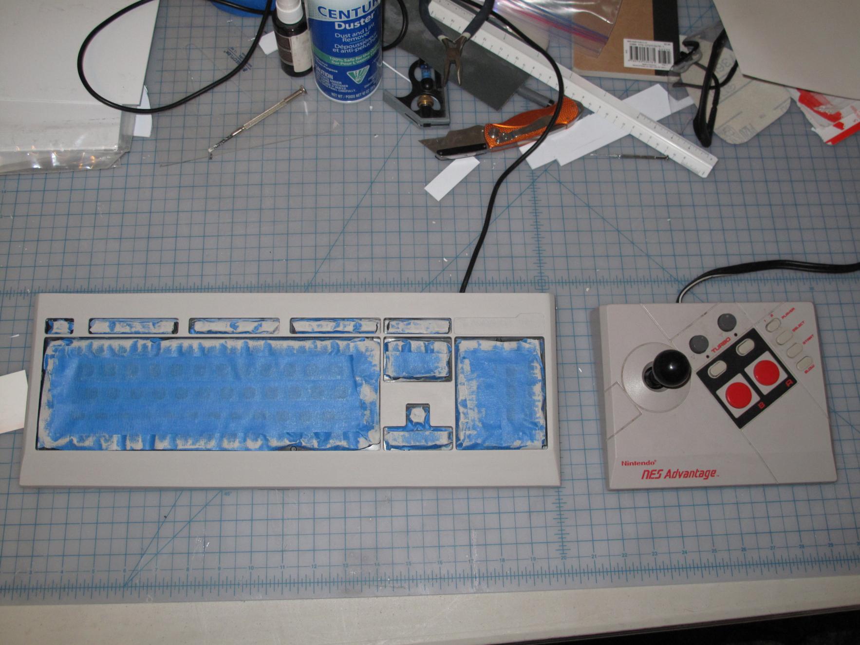
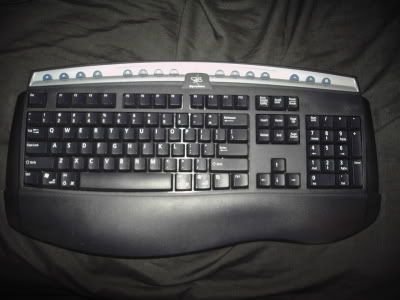
I've decided to mod the keyboard and mouse too. I am hoping to do more than just paint.
This is the closest thing to a Nintendo keyboard I have ever seen. It is a prototype for the US NES.
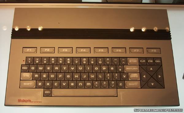
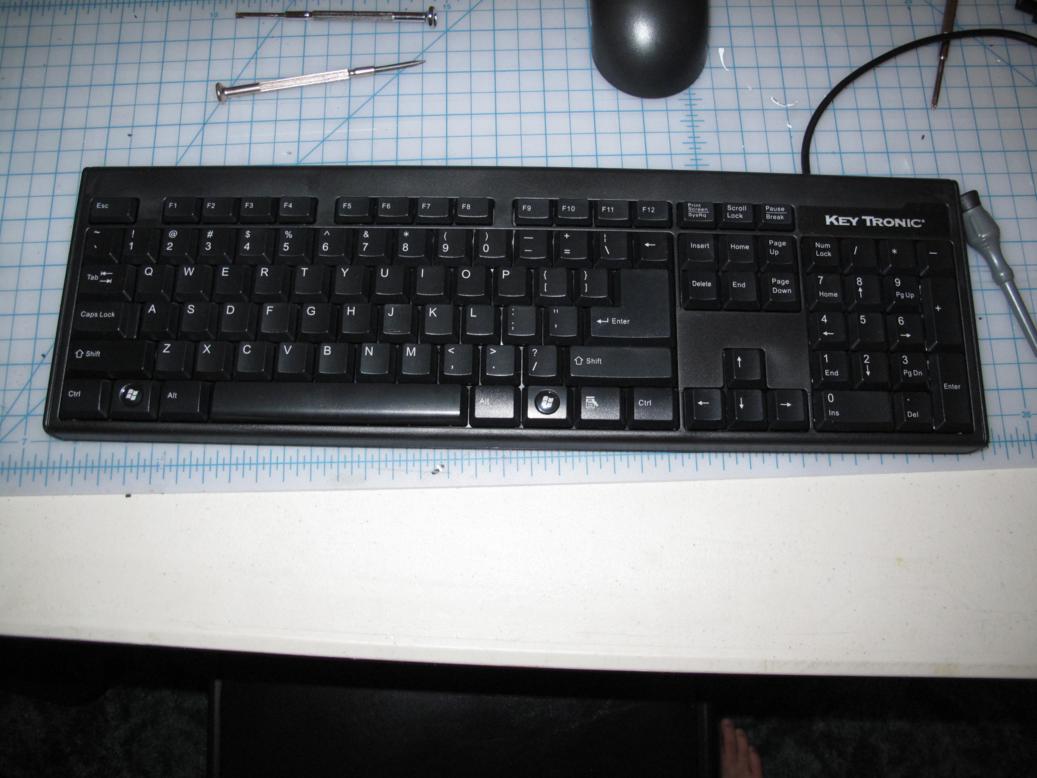
I need to find a PC keyboard with similar keys to mod my current keyboard (seen above). I'm not sure how much I will use from the pic, but a similar final product that is unmistakably Nintendo is what I want.
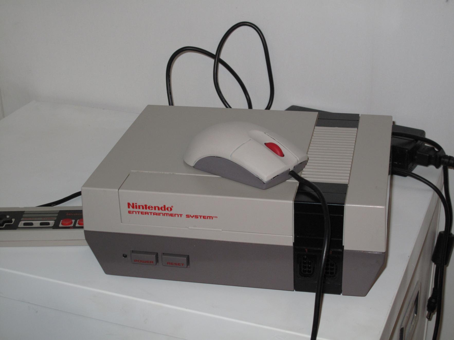
My only other question is about the scroll wheel on my mouse. It is this rubber material and I am fairly certain that it is unpaintable. Has anyone ever dealt with this? Thanks.
6/2/2006
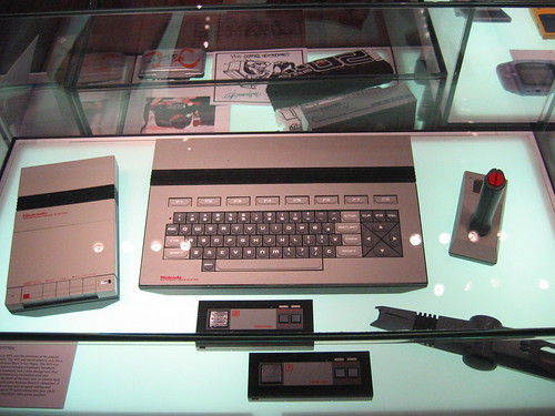
I was in NYC about a month ago. I went to the Nintendo World store. Inside they have a mini-museum of Nintendo items. There was a prototype for an American Famicom there that later became the NES. It's called the Nintendo Advanced Video System and was only seen once to the public in 1984 at CES. It was never seen again until the opening of the Nintendo World store, where it is the only place where you can see one today. Part of me thinks that only one was ever made.
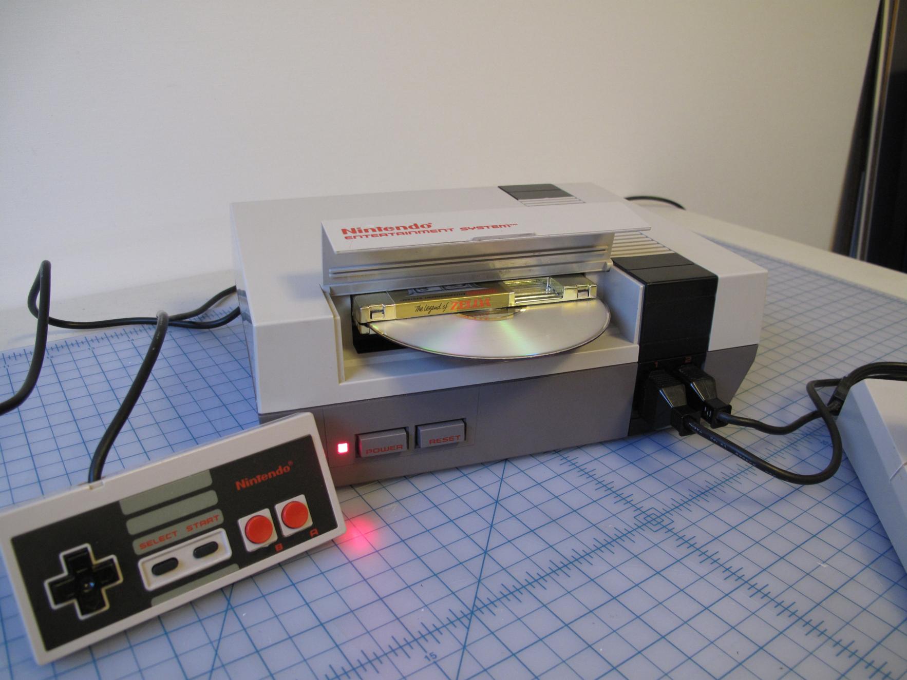
You can see the whole setup here
-------------------------------------
The only time I really don't feel bad double (or triple in this case) posting is in my own worklog.
Here's what I worked on today. It's not a lot but the next parts kinda have me scared (bondo and painting).
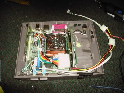
Here's the mobo in the case, the power, reset, and LED wired up. You can see that the blue IDE and USB jumper are both squished on either side of the power switch. I also have the PSU squeezed in between the ram. It has been painted with liquid electrical tape, but I'm more unsure about heat and just how unprofessional it is to have it there. It just fits so well.
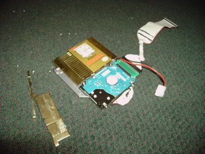
Here is the work I've done to the DVD and HD. They will be mounted to the top in this fashion in a sheet styrene mounting bracket I'm building. You can also see that I have rounded part of the cables to help with bends and the limited airflow that will be in there.
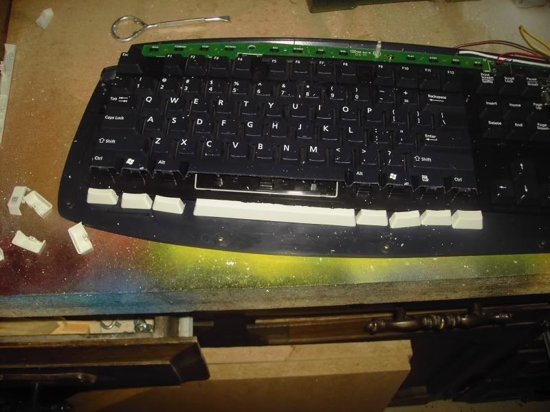
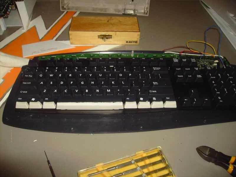
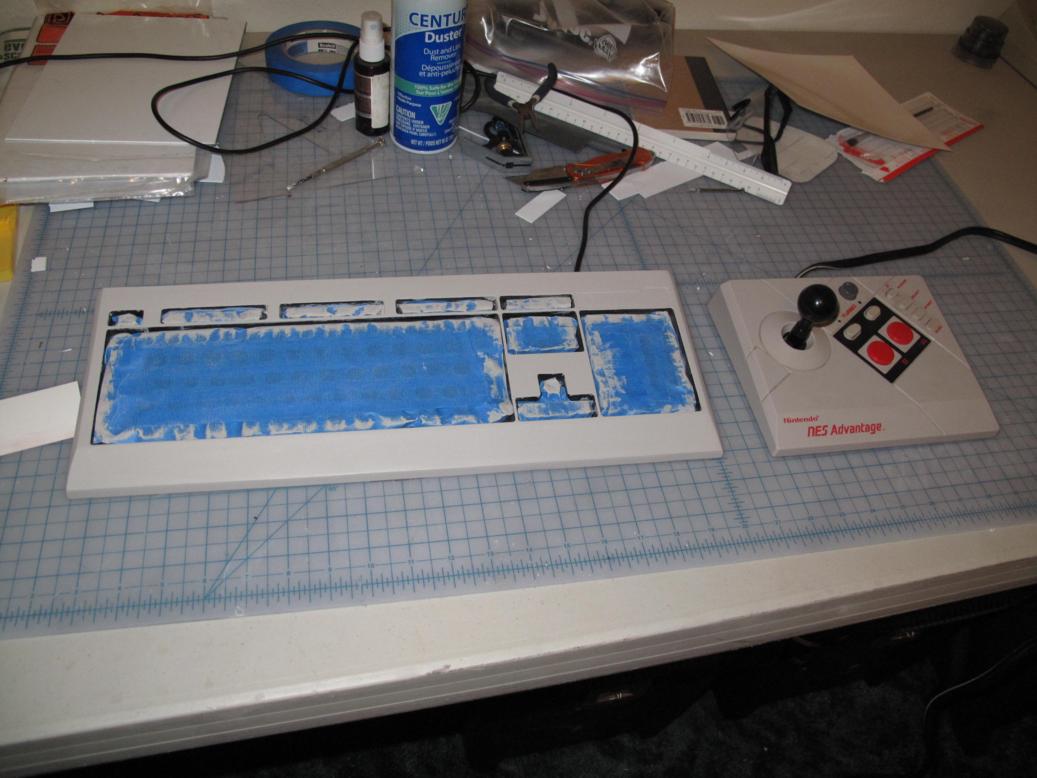
Here I guess is a teaser. This is a pic of the keyboard again. The fifteen media buttons at the top will (hopefully) be replaced with "A B" buttons from NES contollers. The only problem is that I need to get eight controllers that I can hack up to do this. I am also hoping to add "venting" type stripes like on the Advanced Video System pic I have above.
1/29/2008
Well, it's been one week since I said this mod was back online. I'll start with some of the changes I've made since posting last.
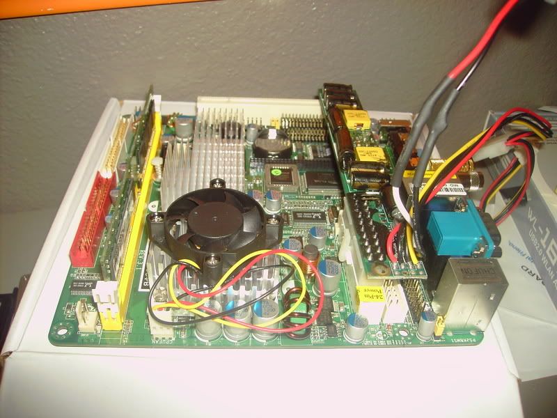
First off, here is my new Mobo. It's the Jetway 7F2WE1G5D-OC-PB. It's a pretty nice little motherboard that only requires 25W and is way easier to cool. This is a huge improvement over the P4 I was trying to cool before. In this pic you can also see the PW-200-V from mini-box.com. It's 200W, which will be more than enough.
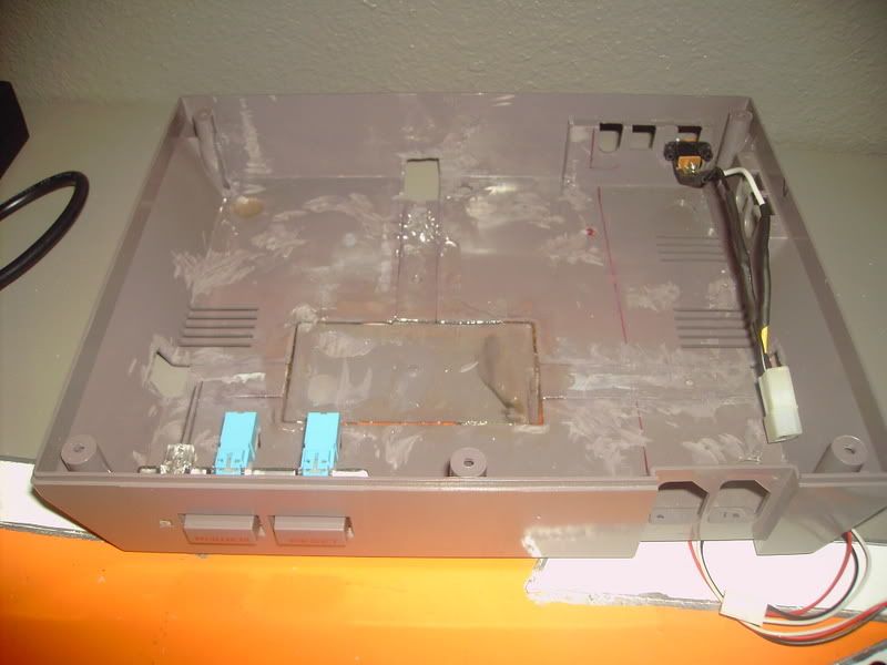
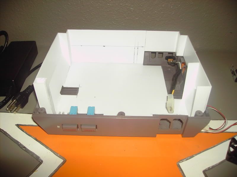
This is as close as I can get to a complete do-over without calling it a completely new mod. Many of my ideas and design elements have stayed, so I am going to say that this is the same mod. Here is the gutted and epoxied bottom half of the NES case.
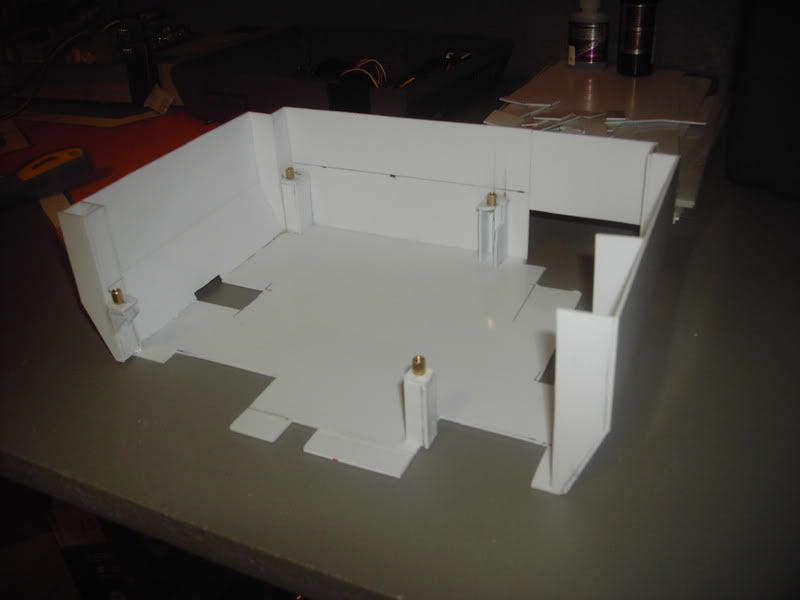
Here is the frame I am building to mount all the computer parts in. It's built out of 1.5mm sheet styrene. When it is done, the mobo, DVD drive, wireless card, HDD, and wireless keyboard/mouse controller will all be mounted to it and will be able to be lifted out of the NES without having to remove a million screws. It is a very tight fit, within a quarter of a mm, so when the lid of the NES is screwed on it will be very secure. I got the idea for this frame from here.
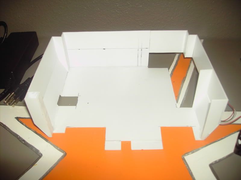
Here is a shot of the frame in the bottom of the NES.
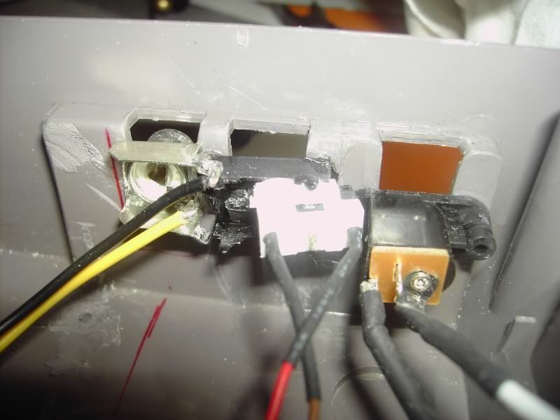
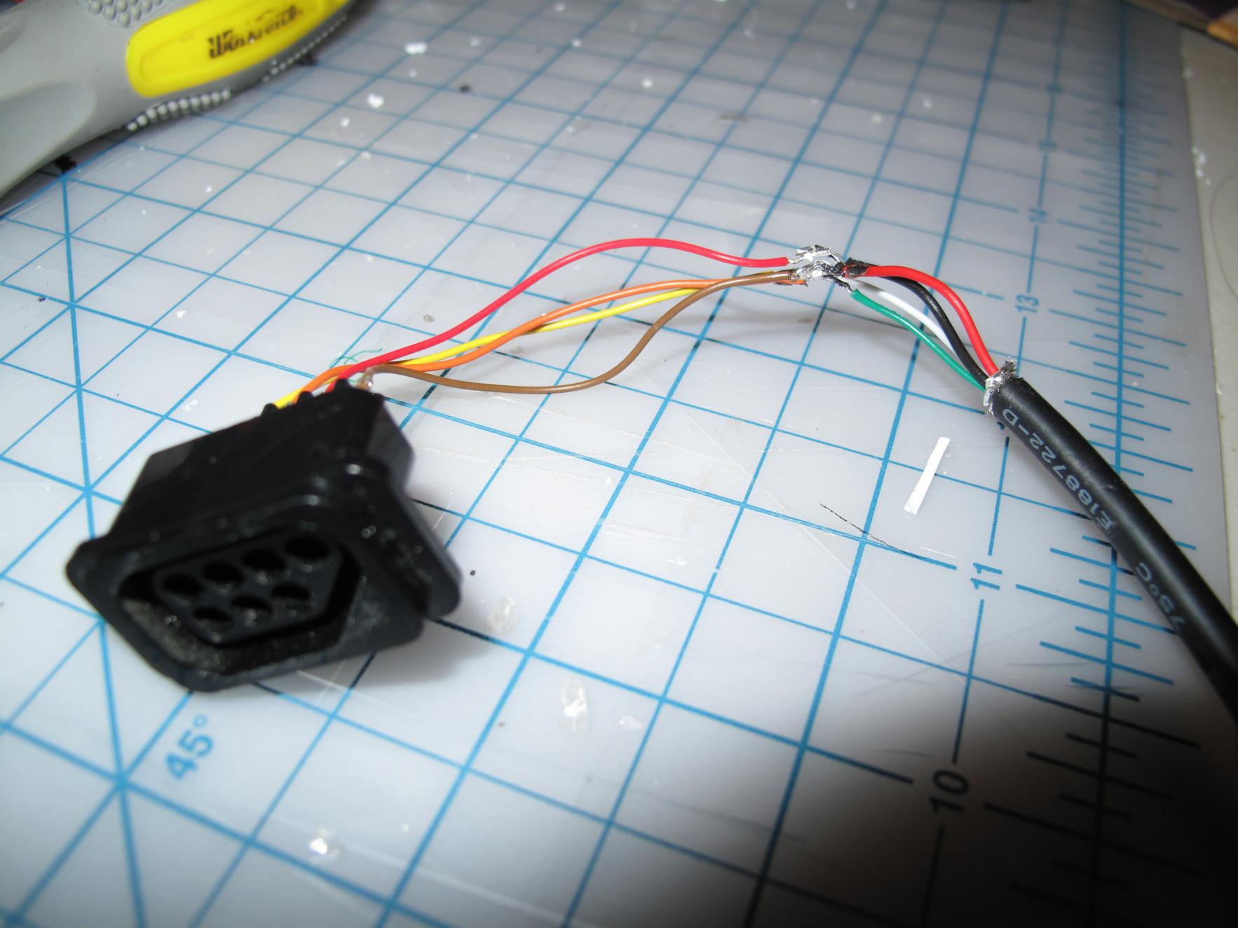
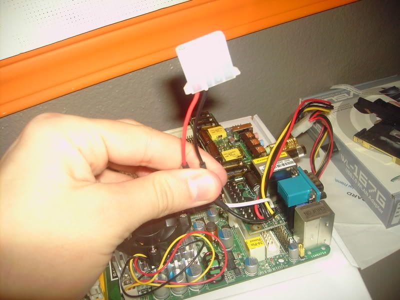
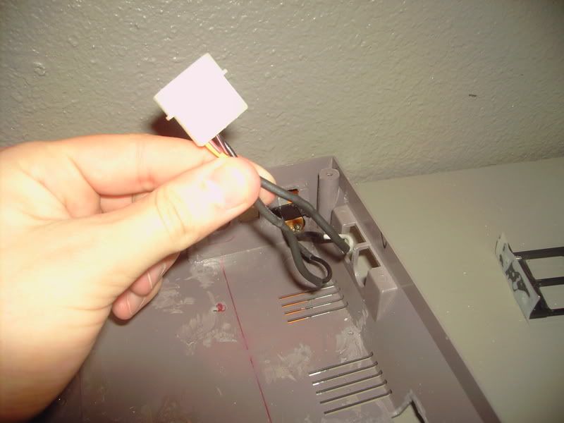
These next two pics show how I will be able to disconnect what's mounted to the frame from what's permanently mounted to the NES case. So far all I have done is the power, which will be connected via a modified molex connector.
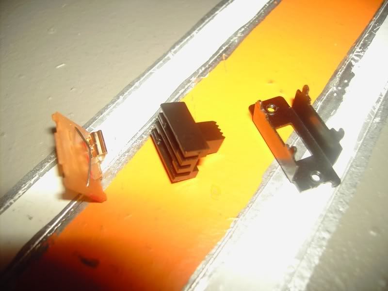
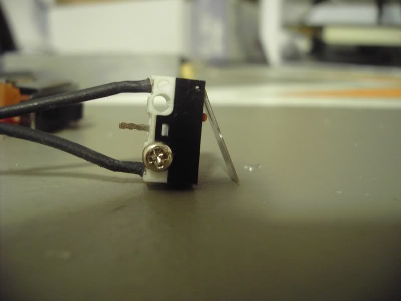
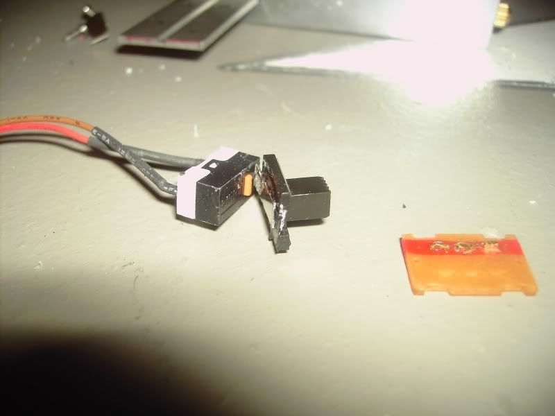
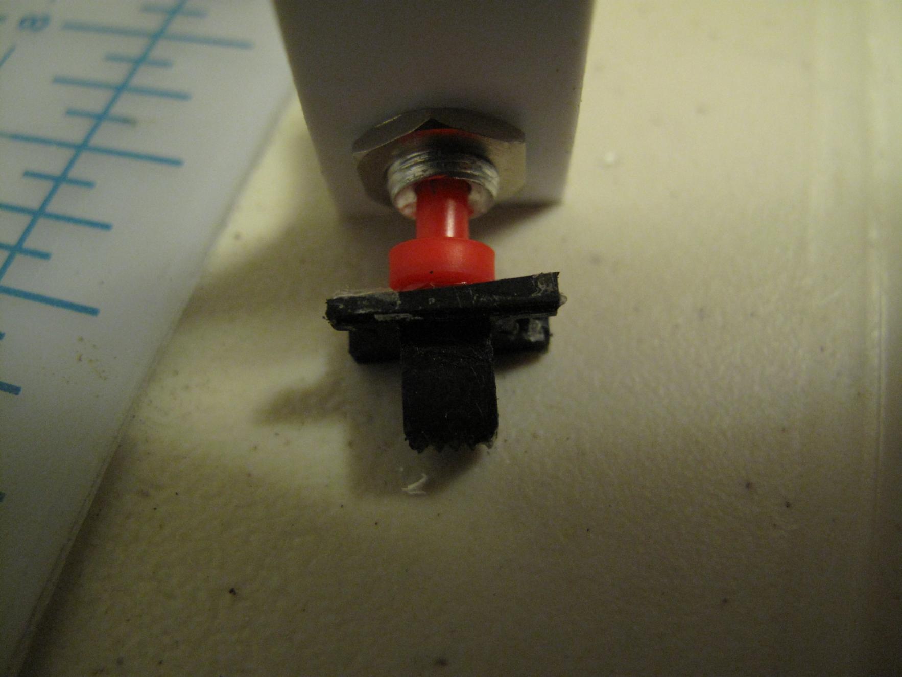
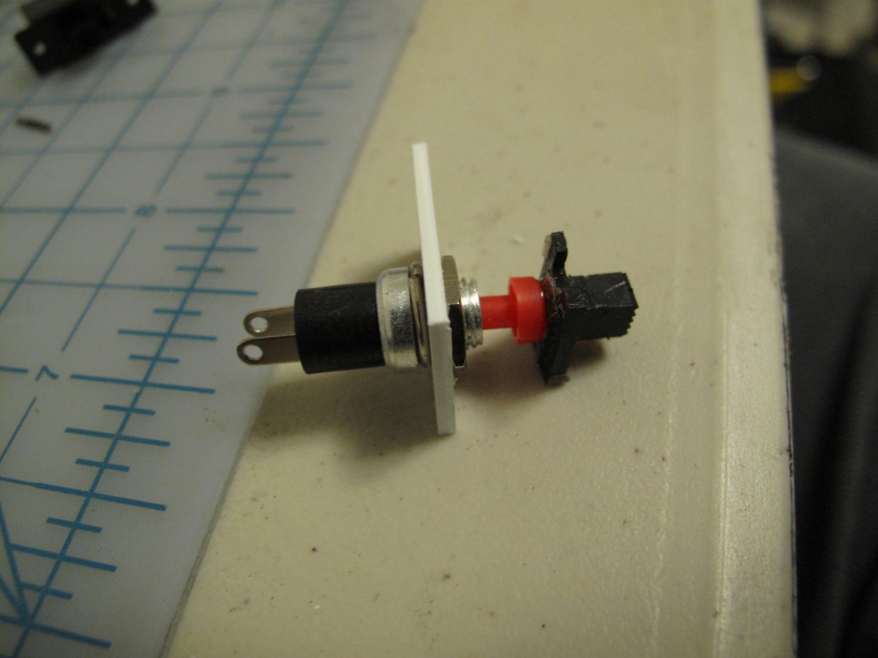
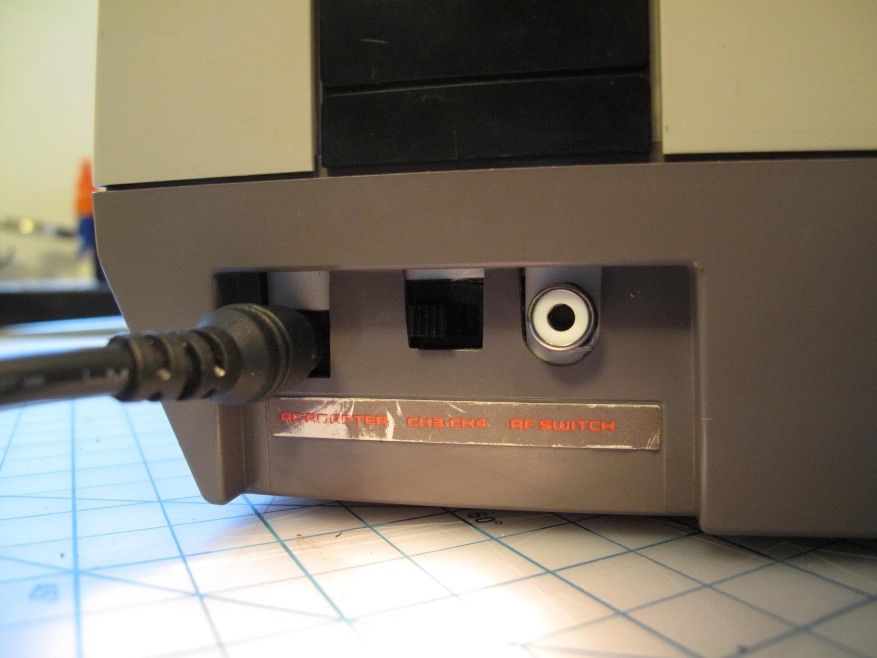
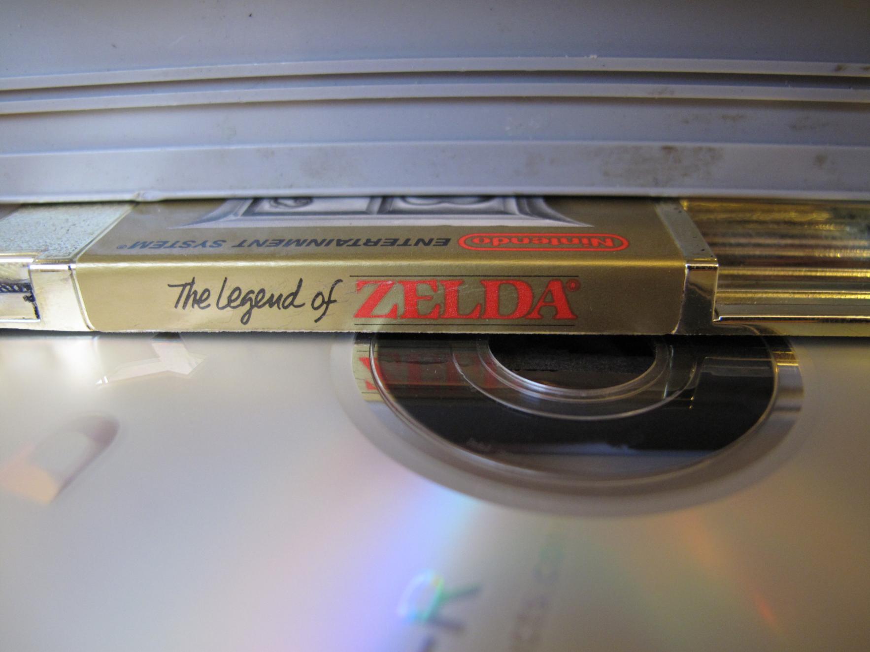
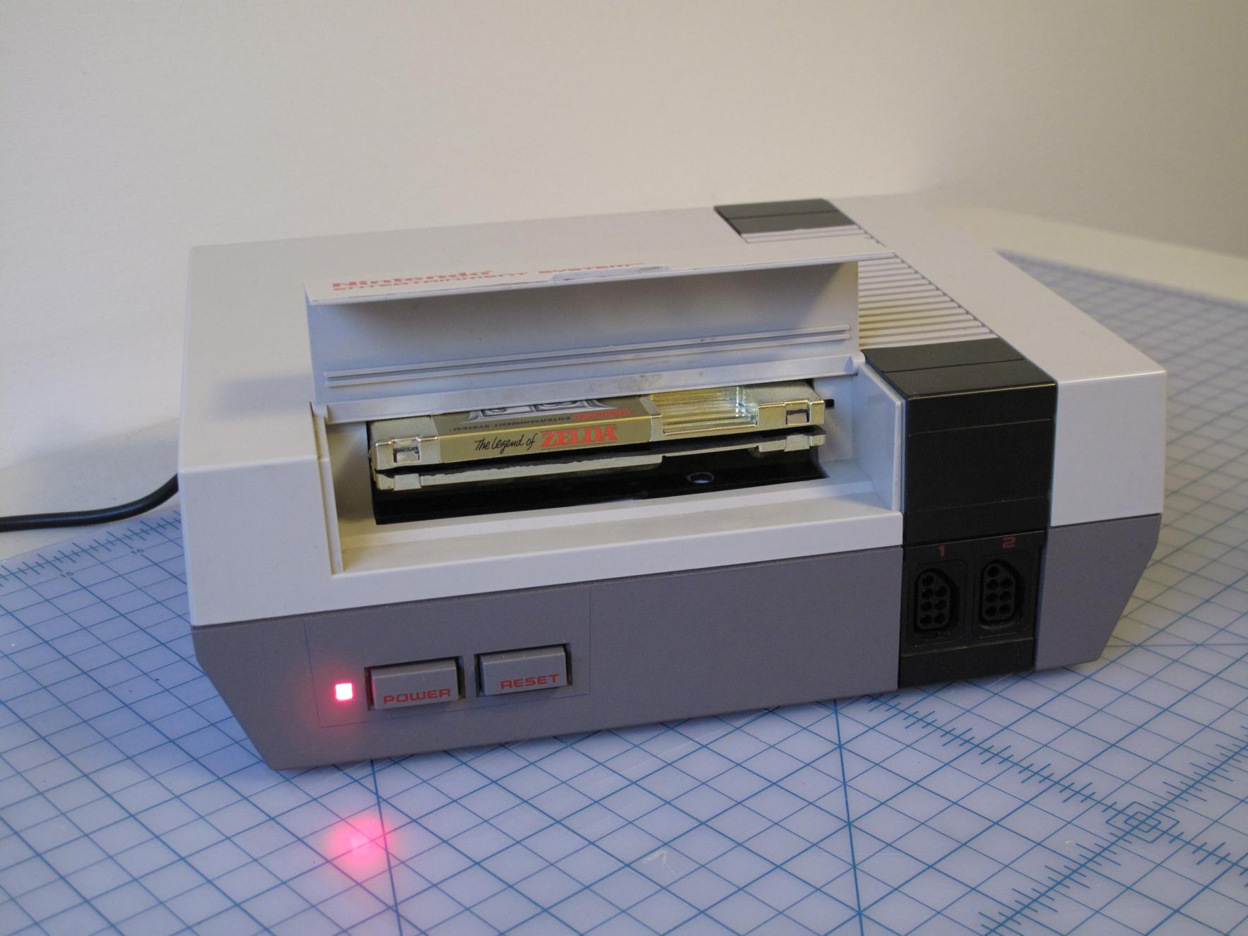
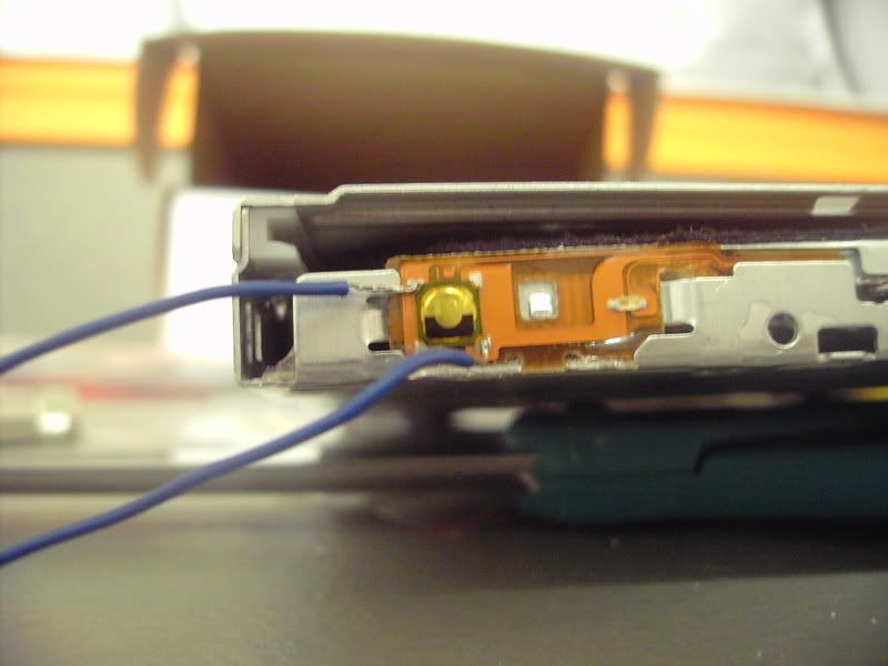
Here is the microscopic button for the slim-line slot loading DVD drive. When the Zelda disguise cartridge is on the DVD drive, this button cannot be accessed. I soldered two lead wires onto the button mounts. These wires will eventually be connected to a button at the back of the case that will be used to trigger the eject button. That button will be disguised as the "Ch3-Ch4" switch. Hopefully anyone but the truest Nintendo fan will be fooled by the outside of this case. From all angles it will still look like a stock NES.
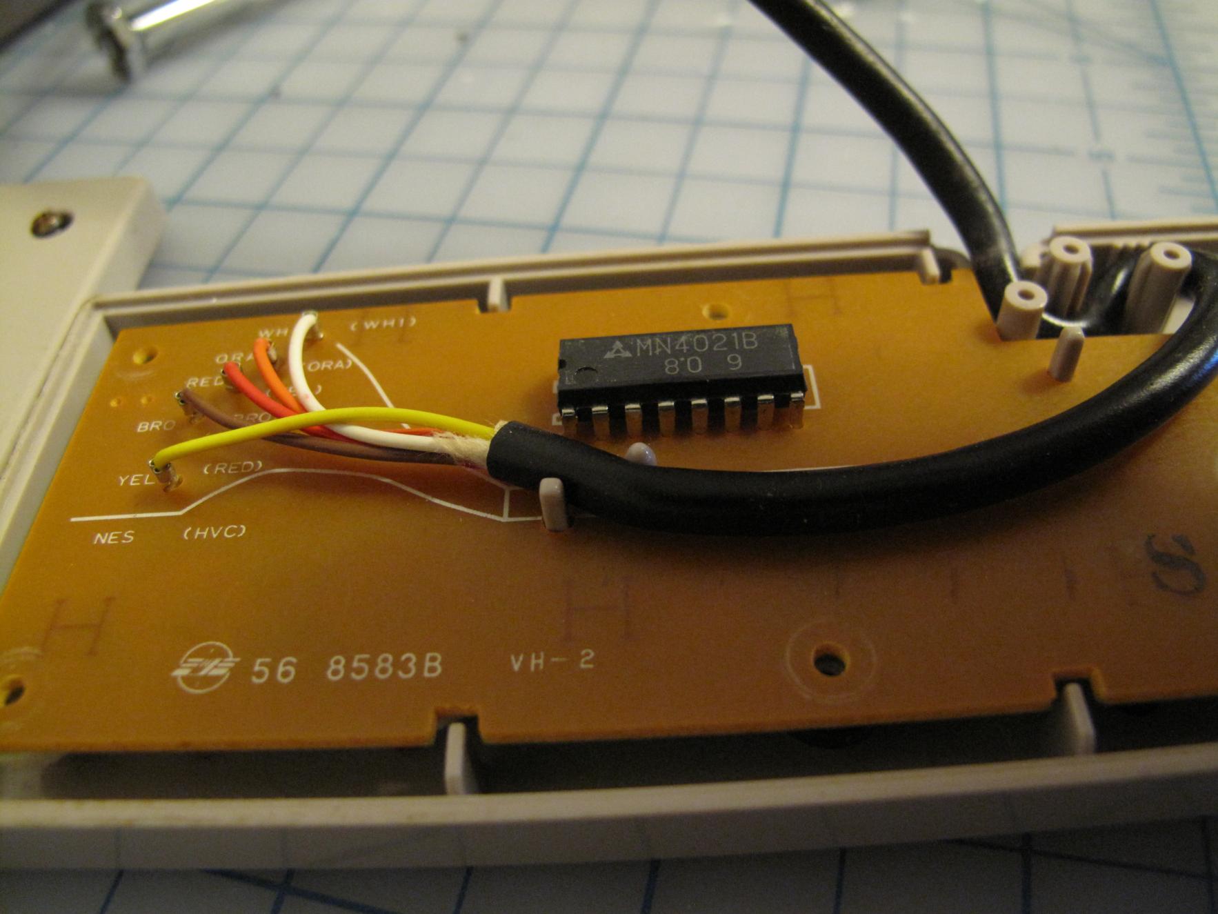
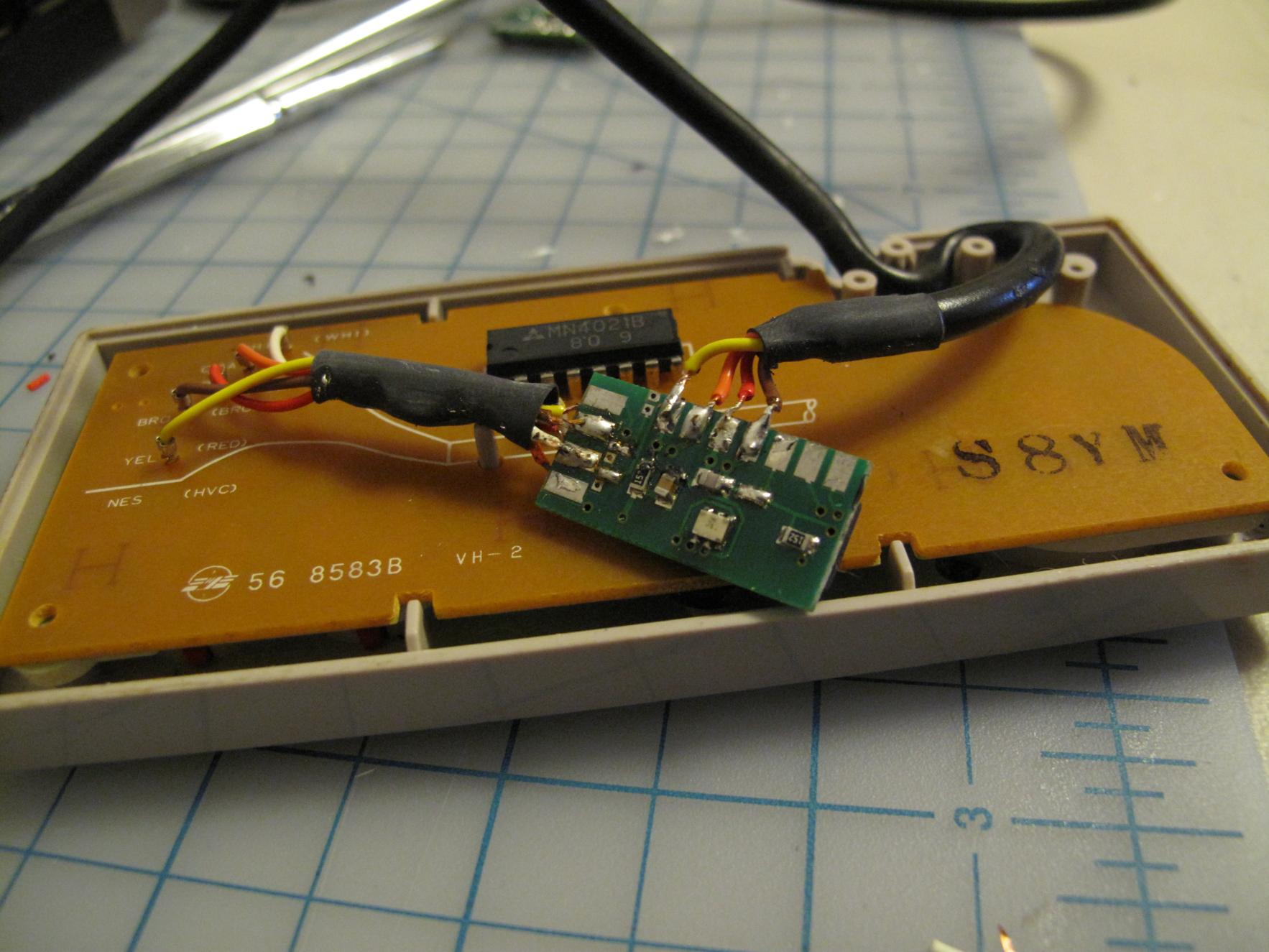
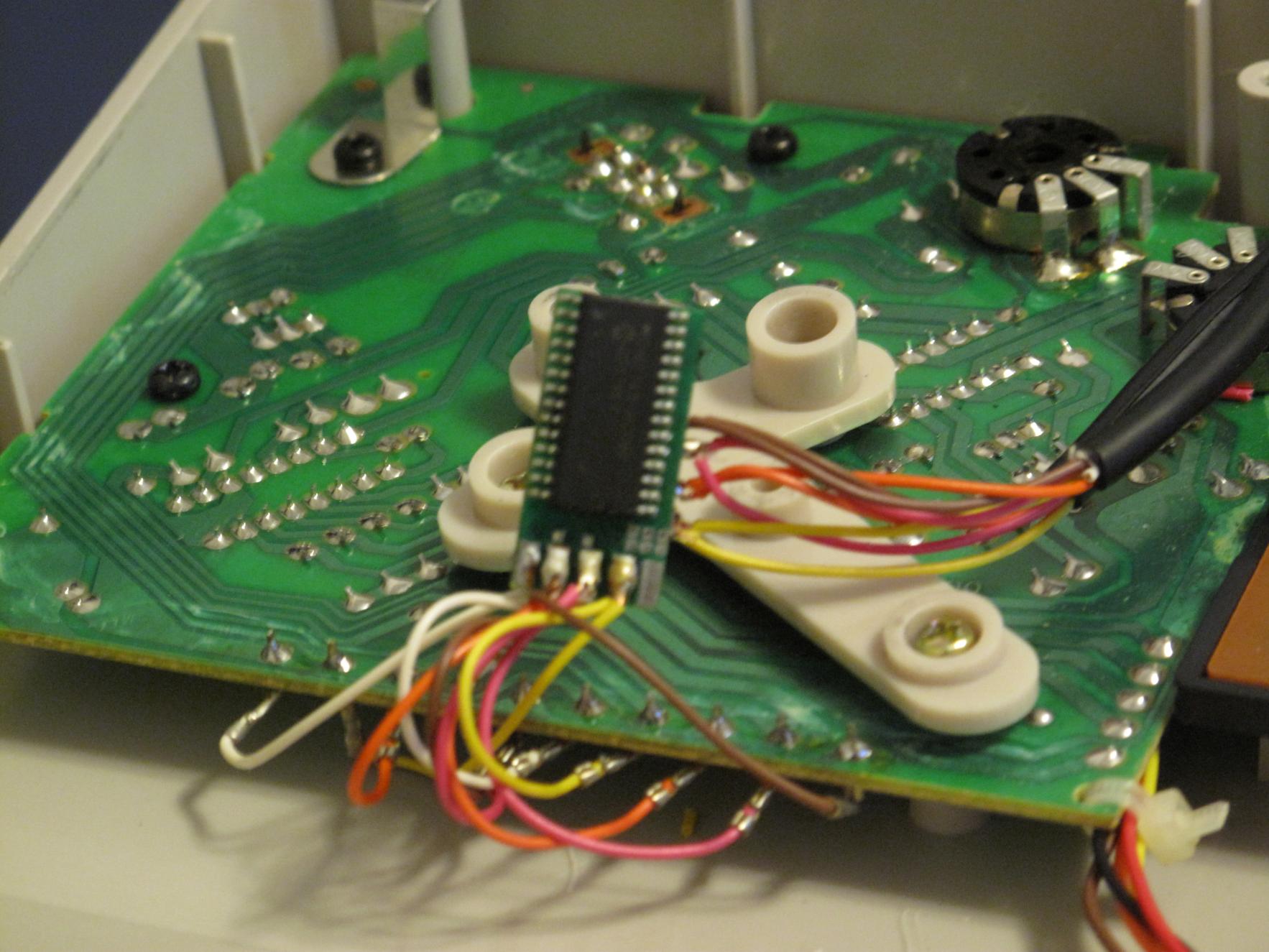
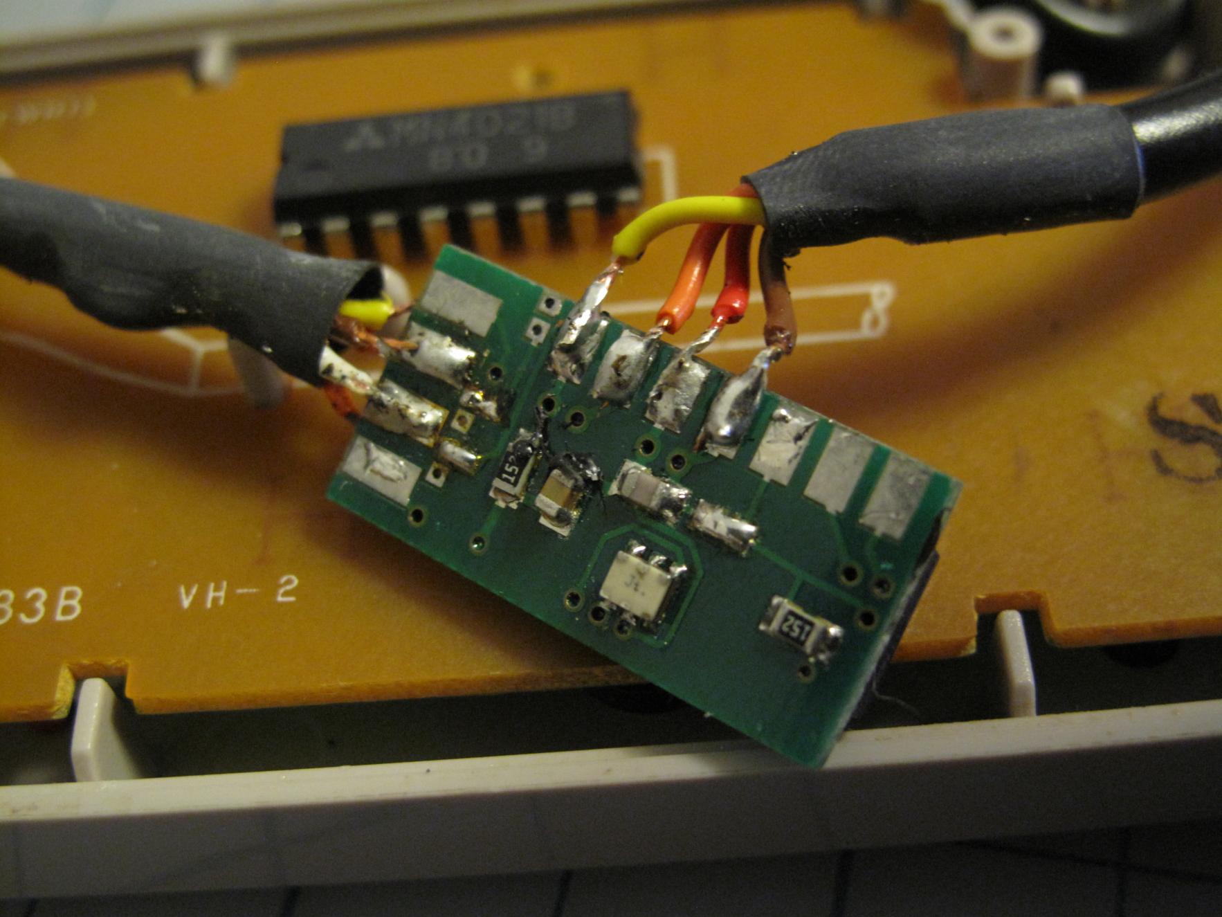
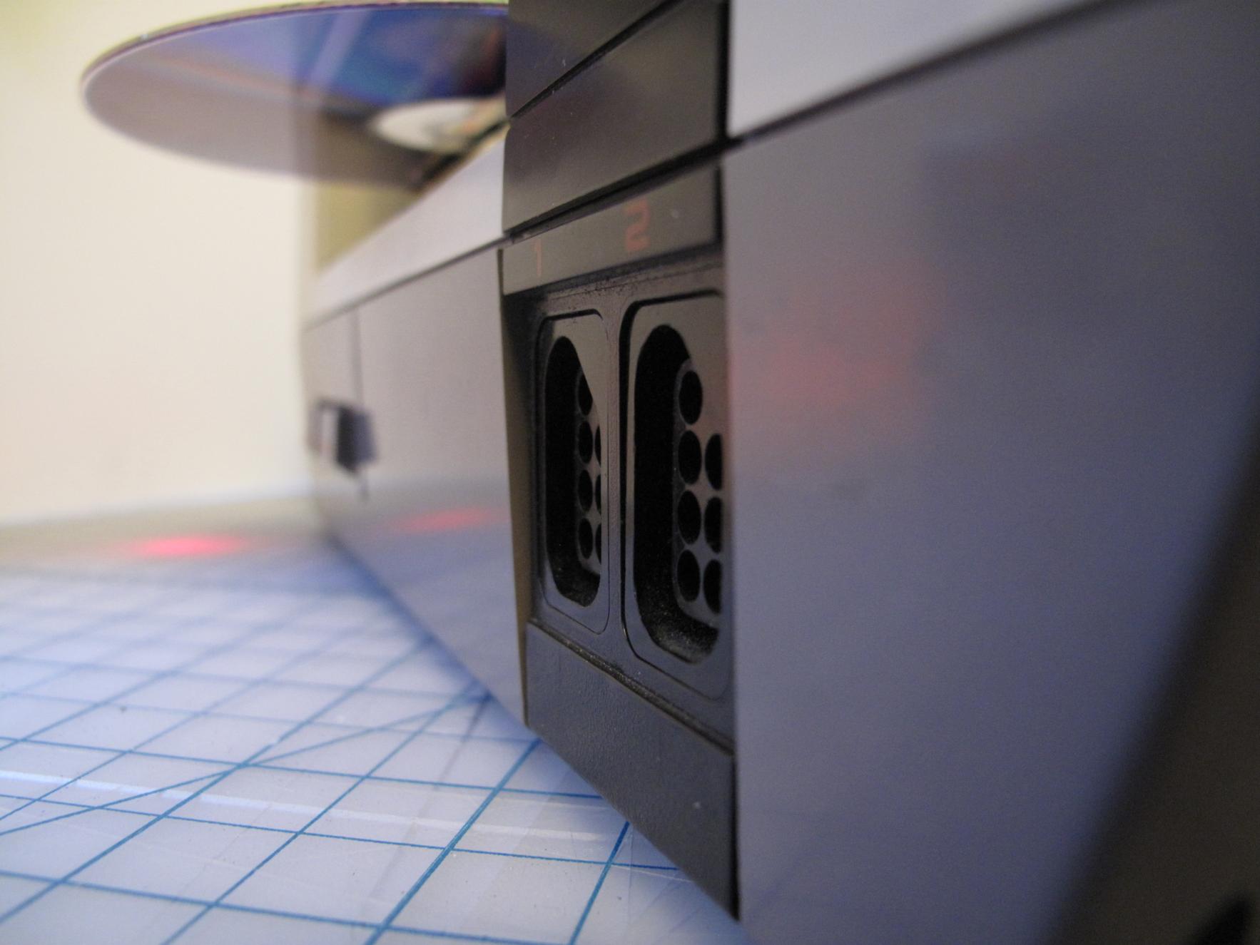
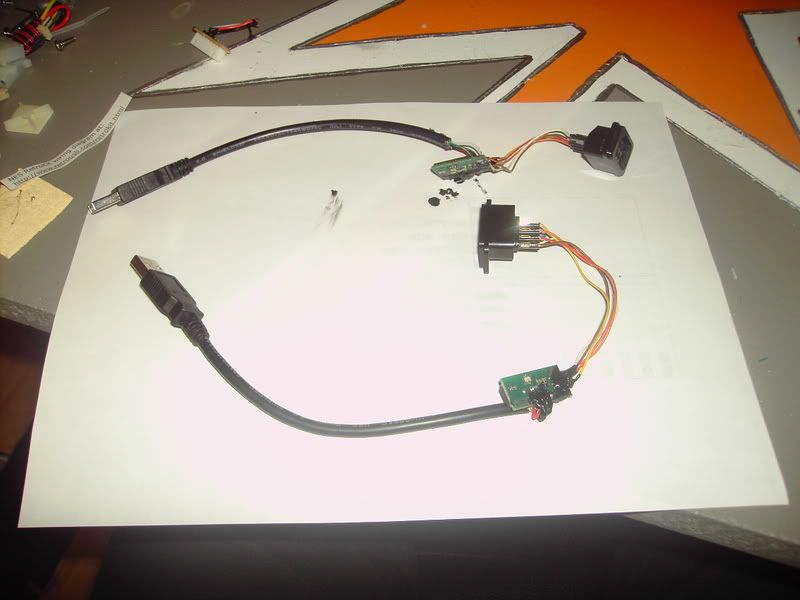
I soldered the chips I got from retrousb.com to the controller ports and then on to USB cords. Hooray for USB Nintendo controllers!
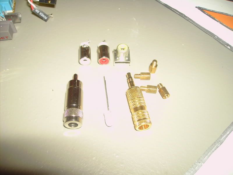
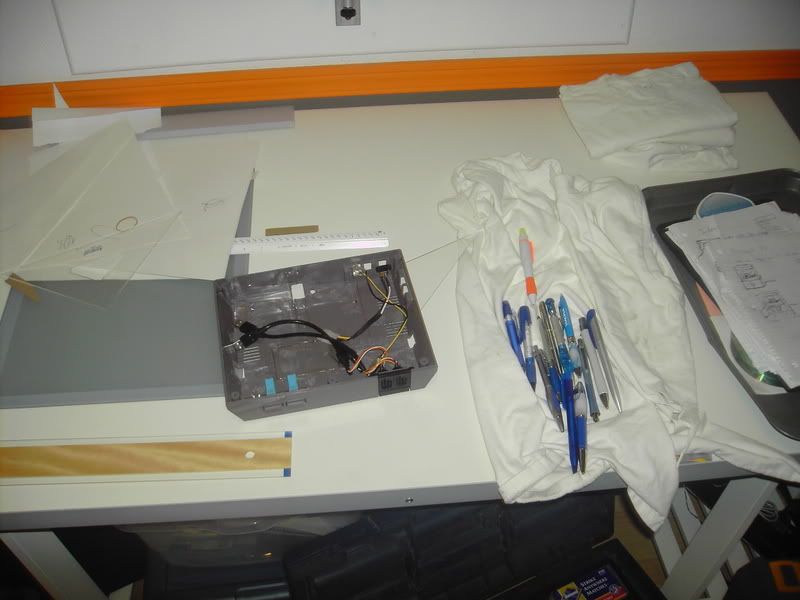
Here is a quick look at what I have left to solder this week. I have the 1/8 jack to RCA, the small RCA extension, and the power LED. The Power and Reset buttons have to be soldered as well. I will (hopefully) make a box so that the power/reset/powerLED are all in one plug, so that I can unplug as little as possible when removing the inner case. There are the mobo mount screws. They will be attached tomorrow (hopefully) to the inner case and then I can mount the mobo for the first time.
That is it for this update. Hopefully by this time next week I will be ordering a 120Gb HD for the mod and I will be starting on the very difficult keyboard and mouse mods. Stay tuned!
1/30/2008
Well, another day has gone by and I have put in many more hours on the mod.
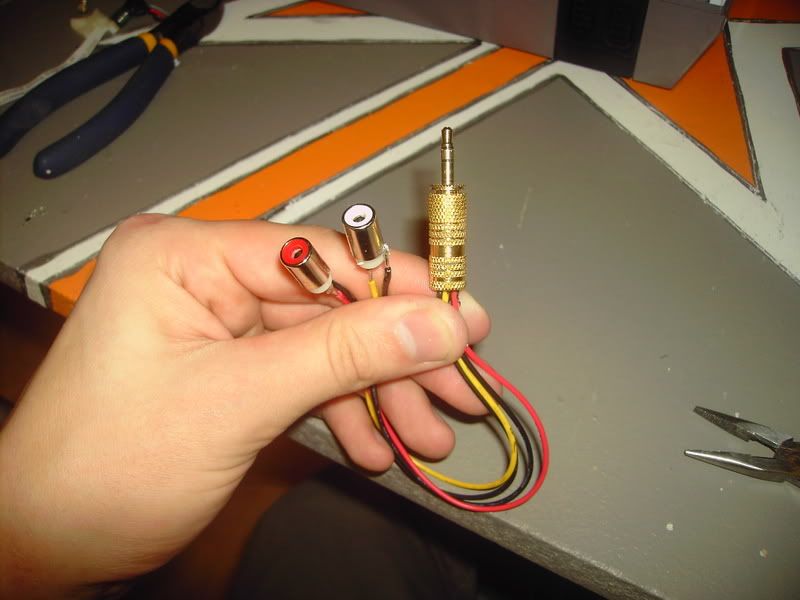
To start things off I will show you that I soldered everything I needed to today except the power LED. Oh well. I built the adapter for the audio and the RCA video extension.
The 1/8in jack to female RCA.
The video extension.
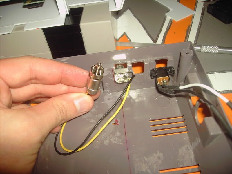
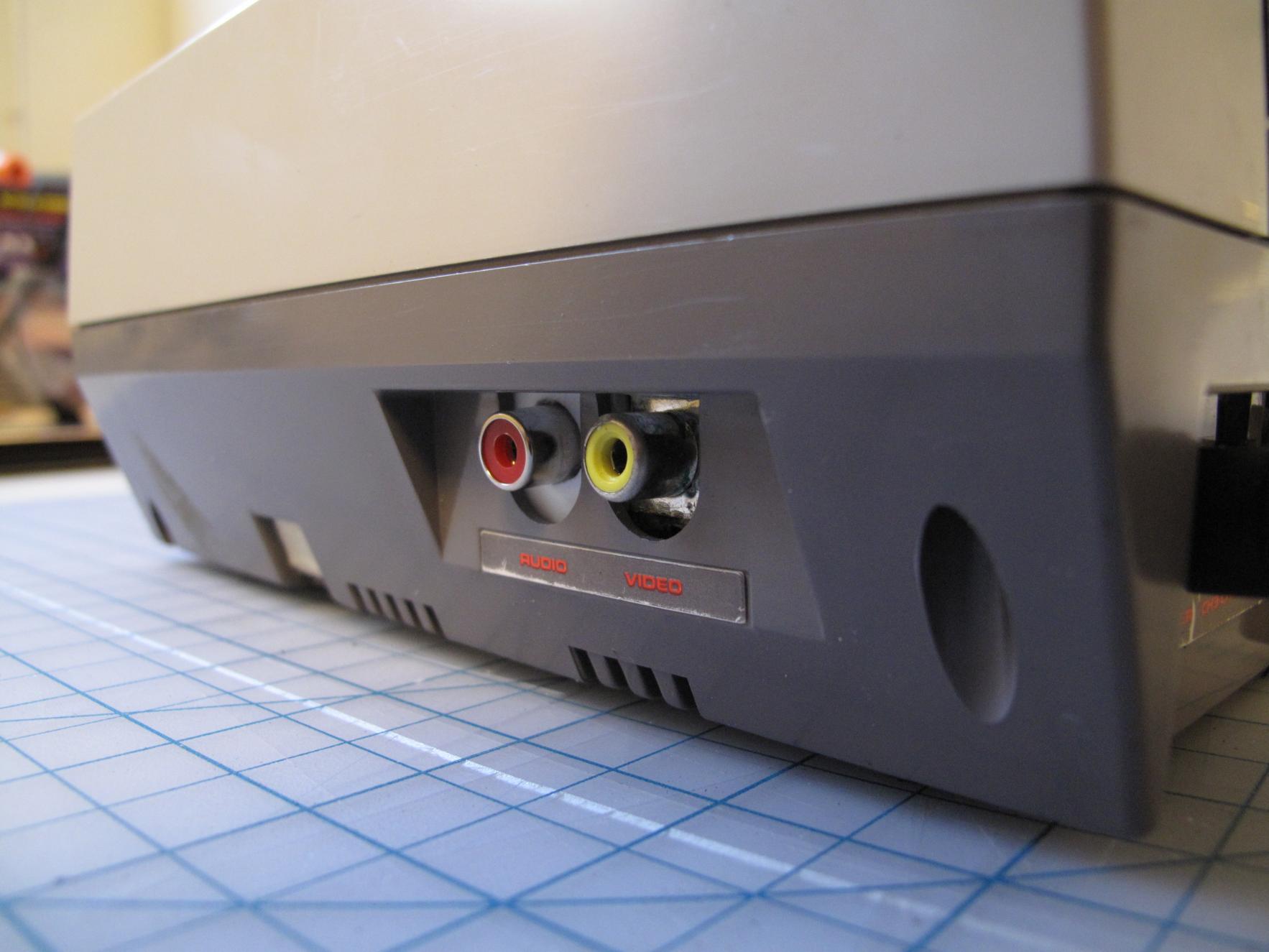
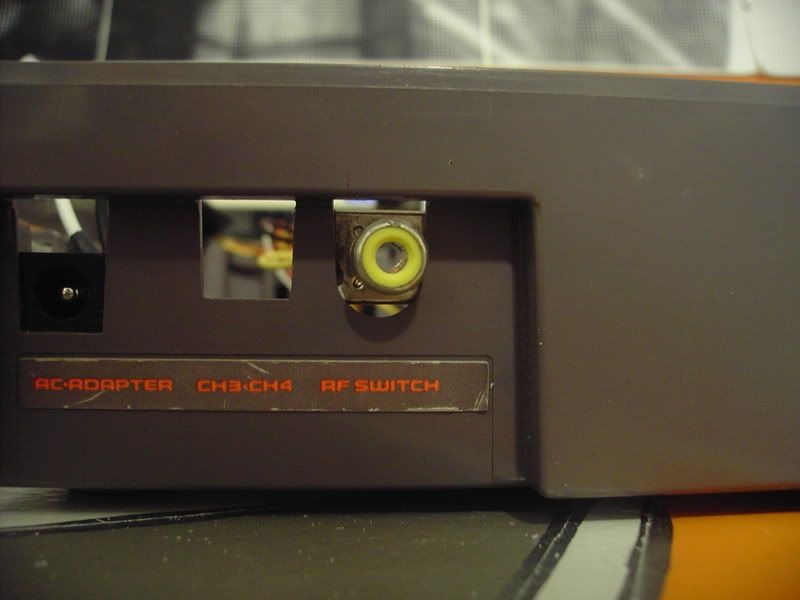
And how it looks from the back of the case. I know this isn't the original position, but I chose to put the audio together because most people think that's the way it should look.
I worked pretty hard today on getting the motherboard mountable. It took a long time because I had to make sure that after things were glued in place and the motherboard was mounted, that the mobo would not interfere with anything else in the case. It turned out that as I was test fitting I noticed that the motherboard was going to hit the video out. At the time I had not yet even mounted the video out. The motherboard mounts were moved 3mm closer to the front of the case than I originally planned because of this. The benefit is that the cables from the mobo can be routed through the back of the case now, so it ended up being a plus overall.
The internal case with motherboard risers.
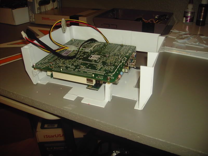
The motherboard mounted. You can see the power and sata cables running through the back.
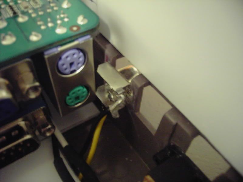
I know it is hard to see, but here is where the video out is now mounted and it is about 1mm away from the PS2 ports.
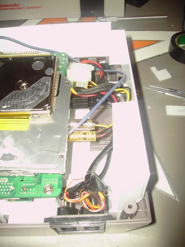
Time for a test fit! I put all the yet-to-be-mounted goodies inside. This included a USB wireless card, the wireless keyboard and mouse controller, the DVD drive, the PSU, the motherboard, the NES controller to USB adapters, the audio adapter, and the video extension. Oh yeah, and the power and reset buttons.
All tossed in, you can see most of that isn't mounted yet.
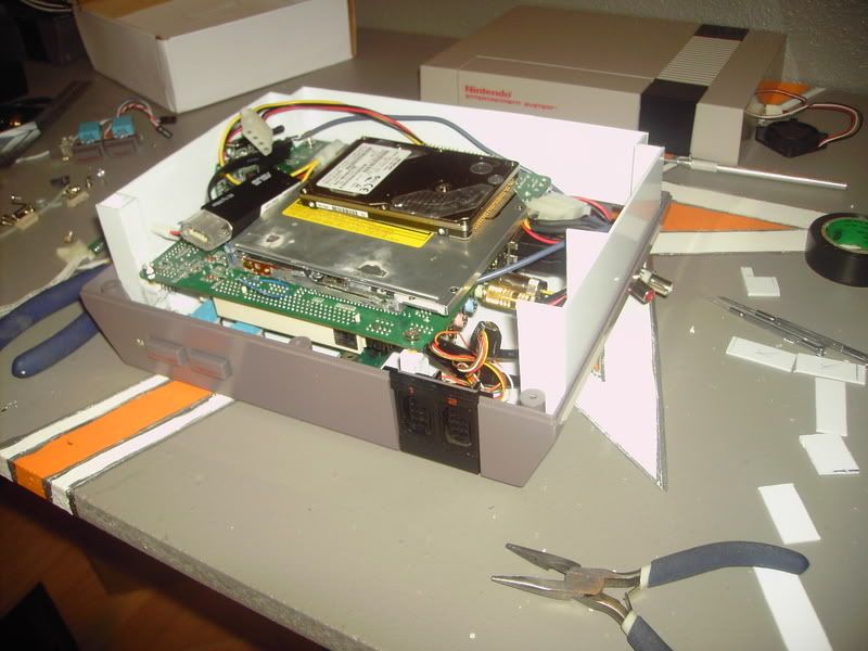
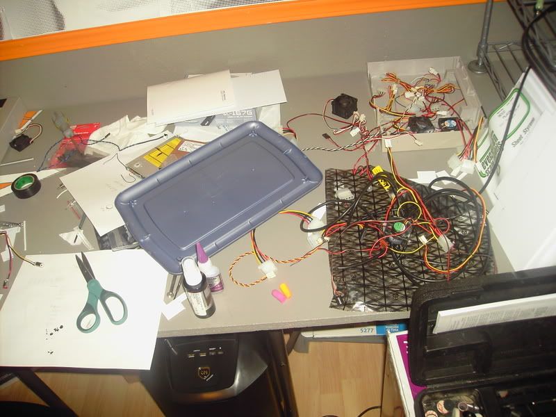
Here is the mess of wires that are plugged into the motherboard, (just so I could be as close to the real thing as possible.)
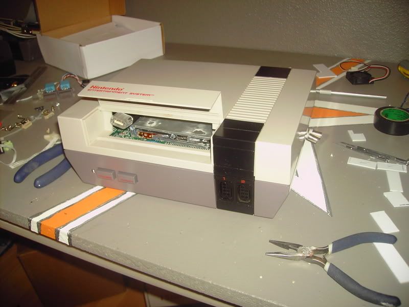
And here it is with the lid on. I opened the door so you can see that there really is all the stuff in there. The lid fits well. There are no screws holding it on in this pic and there is nothing trying to push it off the bottom of the case. This is good, very good.
Afterthought:
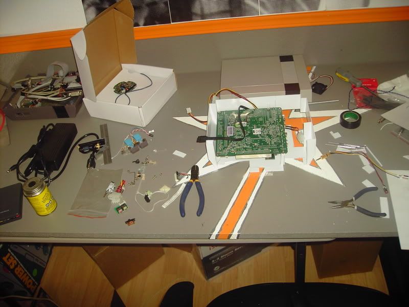
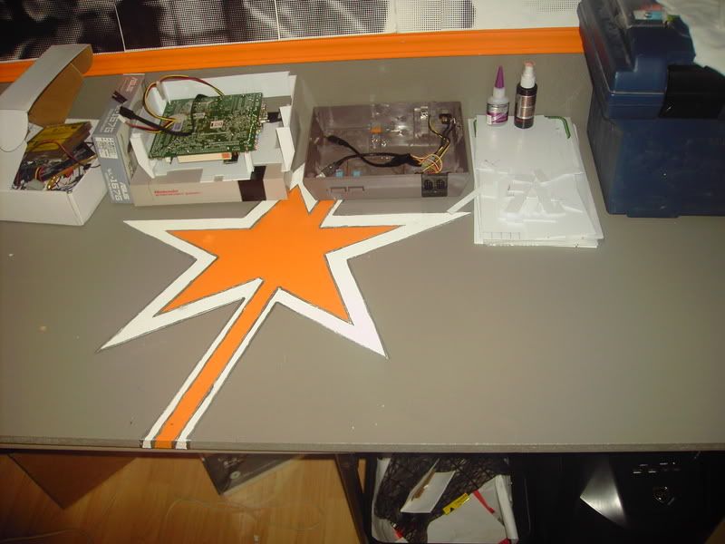
Modding makes my room a huge stinkin mess. This is disgusting. I need to pick up.
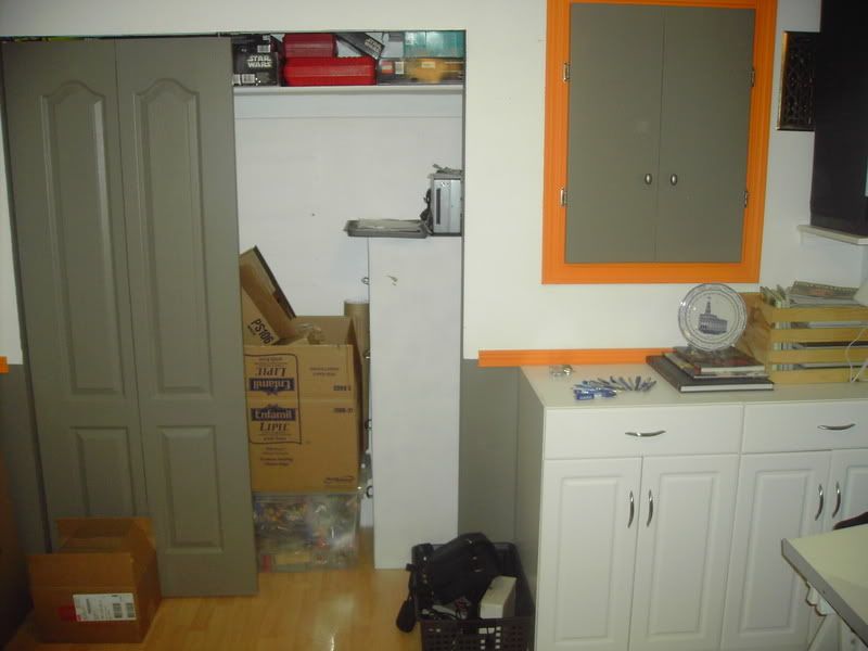
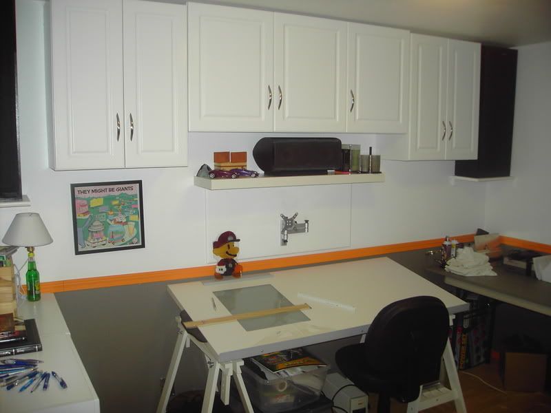
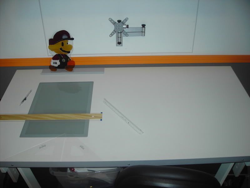
Before:
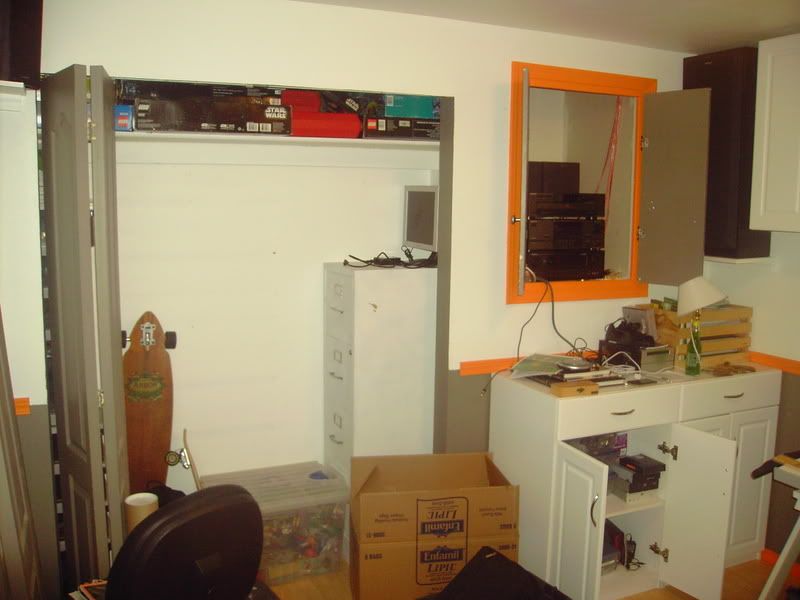
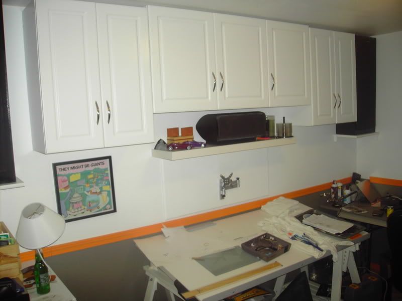
After! This is better.
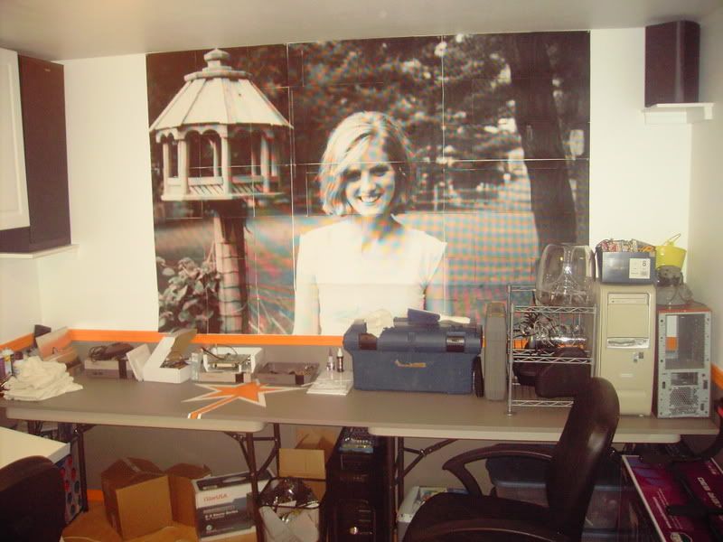
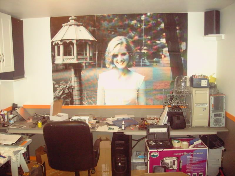
For anyone who is wondering, the poster on the wall is my gf. She is the one who I have the bet with. So far I am winning. I'm putting lots of time into my mod. She does try to keep me from winning by calling me all the time (long distance relationship), but it hasn't stopped me yet. That's right, I have a girlfriend who wants me to mod, and who likes to talk to me. My life is pretty good. Haha.
I'm out for the night.
5/30/2006
This is my worklog of my Nintendo Entertainment System turned to an PC. This is actually a rebuild of the one I've already posted on here. I'm hoping to clean it up a bit and I am forgoing the gaming idea. It's really hard to make it a gaming PC and not cost effective. Instead this will be a media center and rom machine.
That being said this case will have no new holes to the outside. No holes for mobo outputs or anything. I will use existing holes to do a similar/same job as the component in that place did before.
Here is the case. It needs to be cleaned up a bit, but that is always bset done near the end, right before final construction so that it doesn't get dirty while modding.
Here is the inside. I've already cut out the "T" and epoxied the remaining plastic back on the bottom. It needs to be sanded still, but being at school with no tools I may have to hold that for a while and work on another part.
Here is a power supply pic. I got this at mini-box.com. It is an incredible 200 watts in that strip. (They also sell an incredible 120W pico PSU that everyone should seen.) I've already glued it into the case where it says "AC-ADAPTER" and it looks perfect.
This is what I got when I ordered two NES kits from retrousb.com for $17 each. For each kit you get a tiny chip and a six foot USB cord. For comparison, Nintendo controllers had a seven foot cord. The little paper that you can't read in the pic says,
"NES RetroKit wiring diagram at:
http://www.retrousb.com/retrokit.html"
Here are the modded power and reset buttons. I got these thin and easily solderable buttons here.
Here are my DVDs drives. The one on the left is the one I had in my old NES PC and is just a combo drive with no burning capabilities. The one on the right is a Panasonic UJ-845-B. Here are the stats: DVD-RAM 5x, DVD-R 8X, DVD-RW 4X, CD-R 24X, CD-RW 16X. Both are modded with DEAD Zelda carts. I am not a murderer.
Here's my real basic Toshiba 60Gb laptop HD.
Here's the mobo. It's a mini-atx form factor, Commel LV-670 board. I have a 1.8Ghz P4 in it and a 1Gb stick of cheap gigaram DDR. The cooler is a pretty cool copper cooler for 1U servers. It says that it is rated to 2.8Ghz, but I doubt it.
Here is a cheapo 802.11 b/g PCI card and a jumper/header for audio. The header has a stereo A/V converter so it can go out to a TV since that is my goal to have this look stock and function like an old NES.
Here is the Gyration wireless keyboard and mouse combo. The USB reciever has been rewired to be really short and to fit inside the NES since I don't want anything coming out of the finished product. The only problem is that I rewired it backwards (doh!) so I'll have to do it again. [On a side note Nintendo went to Gyration to have them make the gyros in their new Wii controlers]
This pic has a USB jumper for the mobo. This jumper can be unplugged from a small PCB that has the female USB part on it. I am hoping to use this USB jumper 'molex' type connector and disconnect it from the PCB and then resoldering/wiring that to the retrokit chips. The chips would also be soldered/wired to the 'molex' connector that leads to the NES female controller ports. This way I could just unplug a few cords when I want to work on something inside the PC and have easy access.
Last pic has a question attached to it. On the left we see the USB mobo jumper that came with the mobo. In the middle we see an extra jumper that I have and would like to use. On the right is the USB cable that came with the retrokit for the controllers. The one I want to use has a little bit of plastic guarding it from being plugged in the USB jumper place on the mobo. The one on the left has more black wires than the middle one I want to use, but the USB cable that came with the kit has only one black wire. Here's the question: Is it okay if I just pull out the little plastic guard and use the jumper I want anyways for the controller kit? What do the extra black wires do? They are just extra ground, right?
I am going to be constructing an inner box for all the parts that can be removed when I want to work/change something on the PC. I have 2mm sheet styrene and it will be perfect. Give me your oppinions and ideas.
6/1/2006
I've decided to mod the keyboard and mouse too. I am hoping to do more than just paint.
This is the closest thing to a Nintendo keyboard I have ever seen. It is a prototype for the US NES.
I need to find a PC keyboard with similar keys to mod my current keyboard (seen above). I'm not sure how much I will use from the pic, but a similar final product that is unmistakably Nintendo is what I want.
My only other question is about the scroll wheel on my mouse. It is this rubber material and I am fairly certain that it is unpaintable. Has anyone ever dealt with this? Thanks.
6/2/2006
I was in NYC about a month ago. I went to the Nintendo World store. Inside they have a mini-museum of Nintendo items. There was a prototype for an American Famicom there that later became the NES. It's called the Nintendo Advanced Video System and was only seen once to the public in 1984 at CES. It was never seen again until the opening of the Nintendo World store, where it is the only place where you can see one today. Part of me thinks that only one was ever made.
You can see the whole setup here
-------------------------------------
The only time I really don't feel bad double (or triple in this case) posting is in my own worklog.
Here's what I worked on today. It's not a lot but the next parts kinda have me scared (bondo and painting).
Here's the mobo in the case, the power, reset, and LED wired up. You can see that the blue IDE and USB jumper are both squished on either side of the power switch. I also have the PSU squeezed in between the ram. It has been painted with liquid electrical tape, but I'm more unsure about heat and just how unprofessional it is to have it there. It just fits so well.
Here is the work I've done to the DVD and HD. They will be mounted to the top in this fashion in a sheet styrene mounting bracket I'm building. You can also see that I have rounded part of the cables to help with bends and the limited airflow that will be in there.
Here I guess is a teaser. This is a pic of the keyboard again. The fifteen media buttons at the top will (hopefully) be replaced with "A B" buttons from NES contollers. The only problem is that I need to get eight controllers that I can hack up to do this. I am also hoping to add "venting" type stripes like on the Advanced Video System pic I have above.
1/29/2008
Well, it's been one week since I said this mod was back online. I'll start with some of the changes I've made since posting last.
First off, here is my new Mobo. It's the Jetway 7F2WE1G5D-OC-PB. It's a pretty nice little motherboard that only requires 25W and is way easier to cool. This is a huge improvement over the P4 I was trying to cool before. In this pic you can also see the PW-200-V from mini-box.com. It's 200W, which will be more than enough.
This is as close as I can get to a complete do-over without calling it a completely new mod. Many of my ideas and design elements have stayed, so I am going to say that this is the same mod. Here is the gutted and epoxied bottom half of the NES case.
Here is the frame I am building to mount all the computer parts in. It's built out of 1.5mm sheet styrene. When it is done, the mobo, DVD drive, wireless card, HDD, and wireless keyboard/mouse controller will all be mounted to it and will be able to be lifted out of the NES without having to remove a million screws. It is a very tight fit, within a quarter of a mm, so when the lid of the NES is screwed on it will be very secure. I got the idea for this frame from here.
Here is a shot of the frame in the bottom of the NES.
These next two pics show how I will be able to disconnect what's mounted to the frame from what's permanently mounted to the NES case. So far all I have done is the power, which will be connected via a modified molex connector.
Here is the microscopic button for the slim-line slot loading DVD drive. When the Zelda disguise cartridge is on the DVD drive, this button cannot be accessed. I soldered two lead wires onto the button mounts. These wires will eventually be connected to a button at the back of the case that will be used to trigger the eject button. That button will be disguised as the "Ch3-Ch4" switch. Hopefully anyone but the truest Nintendo fan will be fooled by the outside of this case. From all angles it will still look like a stock NES.
I soldered the chips I got from retrousb.com to the controller ports and then on to USB cords. Hooray for USB Nintendo controllers!
Here is a quick look at what I have left to solder this week. I have the 1/8 jack to RCA, the small RCA extension, and the power LED. The Power and Reset buttons have to be soldered as well. I will (hopefully) make a box so that the power/reset/powerLED are all in one plug, so that I can unplug as little as possible when removing the inner case. There are the mobo mount screws. They will be attached tomorrow (hopefully) to the inner case and then I can mount the mobo for the first time.
That is it for this update. Hopefully by this time next week I will be ordering a 120Gb HD for the mod and I will be starting on the very difficult keyboard and mouse mods. Stay tuned!
1/30/2008
Well, another day has gone by and I have put in many more hours on the mod.
To start things off I will show you that I soldered everything I needed to today except the power LED. Oh well. I built the adapter for the audio and the RCA video extension.
The 1/8in jack to female RCA.
The video extension.
And how it looks from the back of the case. I know this isn't the original position, but I chose to put the audio together because most people think that's the way it should look.
I worked pretty hard today on getting the motherboard mountable. It took a long time because I had to make sure that after things were glued in place and the motherboard was mounted, that the mobo would not interfere with anything else in the case. It turned out that as I was test fitting I noticed that the motherboard was going to hit the video out. At the time I had not yet even mounted the video out. The motherboard mounts were moved 3mm closer to the front of the case than I originally planned because of this. The benefit is that the cables from the mobo can be routed through the back of the case now, so it ended up being a plus overall.
The internal case with motherboard risers.
The motherboard mounted. You can see the power and sata cables running through the back.
I know it is hard to see, but here is where the video out is now mounted and it is about 1mm away from the PS2 ports.
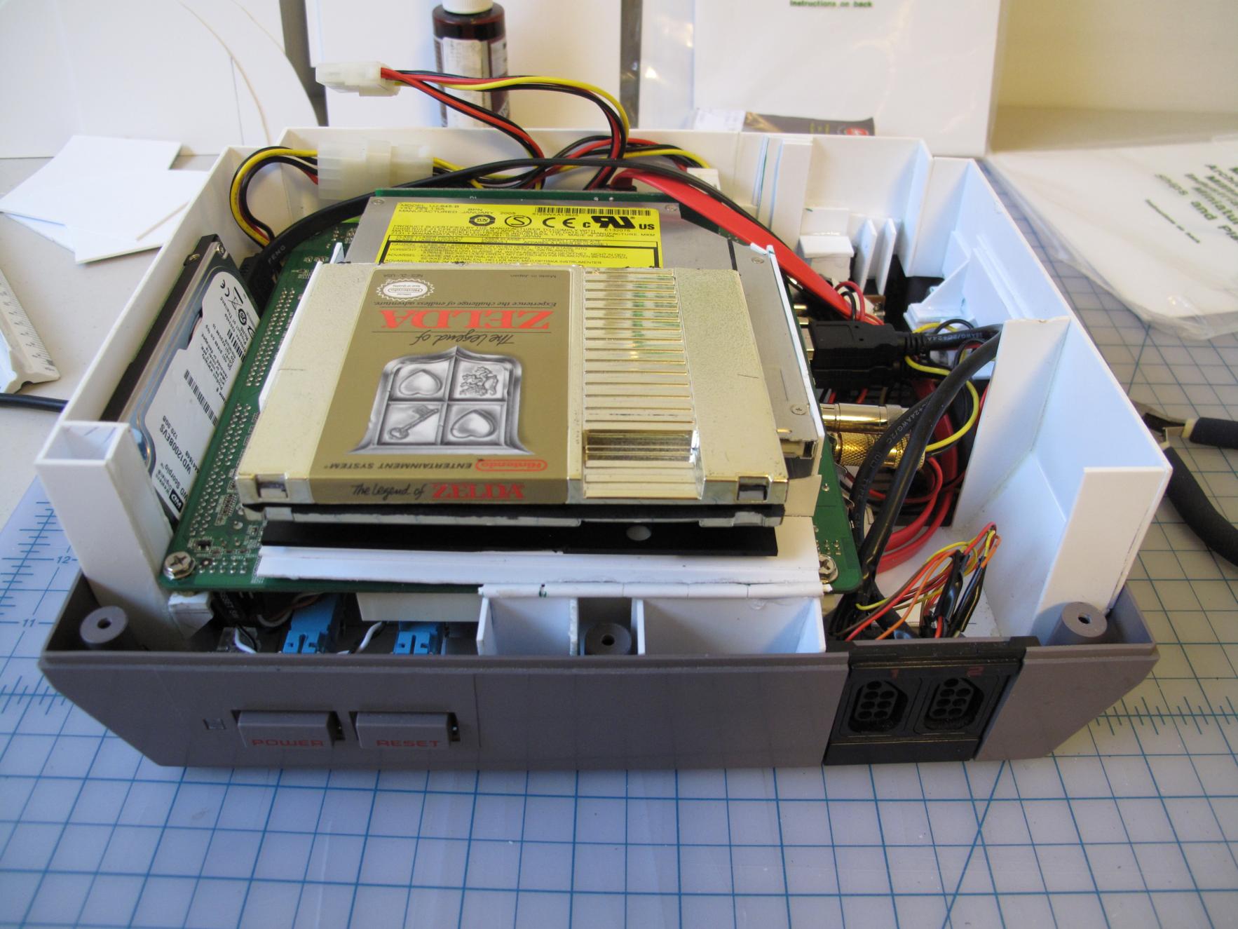
Time for a test fit! I put all the yet-to-be-mounted goodies inside. This included a USB wireless card, the wireless keyboard and mouse controller, the DVD drive, the PSU, the motherboard, the NES controller to USB adapters, the audio adapter, and the video extension. Oh yeah, and the power and reset buttons.
All tossed in, you can see most of that isn't mounted yet.
Here is the mess of wires that are plugged into the motherboard, (just so I could be as close to the real thing as possible.)
And here it is with the lid on. I opened the door so you can see that there really is all the stuff in there. The lid fits well. There are no screws holding it on in this pic and there is nothing trying to push it off the bottom of the case. This is good, very good.
Afterthought:
Modding makes my room a huge stinkin mess. This is disgusting. I need to pick up.
Before:
After! This is better.
For anyone who is wondering, the poster on the wall is my gf. She is the one who I have the bet with. So far I am winning. I'm putting lots of time into my mod. She does try to keep me from winning by calling me all the time (long distance relationship), but it hasn't stopped me yet. That's right, I have a girlfriend who wants me to mod, and who likes to talk to me. My life is pretty good. Haha.
I'm out for the night.