Project: parallel HEX (completed!)

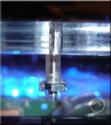
Don't those tubing guides increase your risk of a short?

They certainly would if they came in to contact with anything electrical. However I took many steps to make sure they were nowhere near the motherboard, graphic cards etc. In the images I have posted so far they might look like they are close, but I can assure you they are not!

Thanks to my anal diligence, the system is leak free, yay!

However, it's not all great news. The first pump in the system is running at full speed regardless of the remote potentiometer setting. This is causing havoc with getting air out of the system. The other pump is fine, but I don't want them to run at different speeds or both at full tilt.

It was too late last night to start faulting it, so that's todays job. It's either my wiring, the pot or the pump. It's strange as it was all working fine on the bench for ages. I reckon there may be a dry joint in the pump where I soldered on the wires for the remote pot and moving it made the gremlin show it's self.
 
This is just soo cool watching this thing come together over time. Yeah, i've been reading & watching your project log for a while now.

Curious if you know how much the thing weighs with it filled?

I ask because it's going to suck for any type of transport with it not having handles and/or wheels to move it around ( :O custom acryllic wheels would be tits!). The other option I could see would be to have a padded case for it that opened up either like a clam or 6 hinged sides that lay flat when opened.
 
Weighing it is on my list, just for curiosity. Trust me, this is no lan-rig, it weighs a fair bit already and I have to cart it up the stairs to it's permanent location!

I have completed the faulting, and it is indeed the pump :( . Don't know why it would run full speed but not vary. I even resoldered on the original pot (what a laugh that was) but still no joy. So I've ordered another D5 and hopefully will get here tomorrow. I couldn't find anywhere local that sells them. I might find a use for an unvariable D5 in the future...

I'll have to drain the system down again in readiness for the new pump. Shame, I thought I was going to finish today...

stage_217.jpg
 
I love the water cooling distributor block. It has a slight Matrix/Star Trek Borg look to it. Very cool. :)
 
It's awesome to see it almost done :)

Everyone has its own setbacks. I got one myself yesterday when the RAM decided to die on me right when I'm ready to boot with the new E6420 processor :(
 
I love the water cooling distributor block. It has a slight Matrix/Star Trek Borg look to it. Very cool. :)

black plexi and green water would do the borg justice :D

looks fricking awesome dude. no more uber bubbles like with the 2L bottle of pop? lmao
 
you should submit this to maximum pc.....they have a mod of the month thing and the winner gets a $500 gift certificate to tiger direct
 
cipher_nemo, 0mega and skudmunky, any similarities to The Matrix or The Borg is purely unintentional, although I can see it!

Xilikon, yeah setbacks suck! I had another as you'll see further in this post. Shame about your memory, I once lost mine too but was after a bottle of JD...:p

alkaline, I'm thinking of submitting it somewhere, but I'm in the UK so that $500 from maximum pc is safe for you guys!

So, my other setback. Yes, the damn pump fiasco! I got the other pump and quickly got to modding it before I even switched it on, talk about blind faith in manufacturers. The first thing I noticed was this was a 1.3 version of the D5 pump - the one the huge capacitor and 'refined' circuit board.

stage_218.jpg


I set about taking out the internal pot, and here's why you should be careful of the wattage of your soldering iron. I use a 15W iron, which was obviously too hot for this circuit board - the solder-pad and track came out with the pot! Shit! Shit! Shit! Had I just screwed a brand new pump? I traced the (once present) solder-pad to a smaller pad and soldered my wire to that one. Closed it up, put it into the water circuit, filled it and tested it. This pump wouldn't vary either! What the hell is going on I thought!

So I drained the system again (thank got for the drain circuit!) and opened it up and what did I see? The glue (from the hot glue gun) used to hold the wires in place had came loose and so had that solder-pad. Close up macro shot of the ensuing mess. These pads are tiny!

stage_219.jpg


Not a good day for pumps. After testing resistance with a meter I soon found out that the smaller pads have a coating on them that means solder won't take. Not giving up I traced the circuit and soldered my external pot wire to the tag of capacitor C7, which looked to have a bit of dodgy solder anyway. A long story cut almost shorter, it worked! Now both pumps vary in speed from the external dual gang potentiometer. Phew!

Fast forward a bit after leak testing again, I took the plunge to power the hardware up. Thankfully no problems - it's alive!

With flash:

stage_220.jpg


Without flash:

stage_221.jpg


stage_222.jpg


Here you can see the six UV LEDS I added to react the coolant and the intake fans on the side. I did add filter material to these, but removed it after because it affected the temps quite a bit (fan restriction was too much). Running the X3 benchmark demo here to heat things up.

stage_223.jpg


You might have wondered why I was so determined to get the pumps able to be varied from the outside. The simple answer is the turbulence in the Collector when the pumps are on full speed. Looks cool, but the Collector and tubing fills up with tiny bubbles of air (as per the Sprite bottle!). Oddly, it only affects the temps by 3C or so, but increases the noise level and probably reduces the life of the pumps.

Here's with the pumps at an acceptable '2' setting. Look at the Collector in the upper right hand part of the image.

stage_224.jpg


Then with the pumps at '5' (or max setting now). That haze is the bubbles!

stage_225.jpg


So I'm 99% complete with this build. The temps are pretty good for the overclock which I shall give in another post. Before I finish the worklog I'll have some better pictures for you too. I'm off to get some rest!
 
Mysterae that is just awesomeness. I'm glad you got it all up and running. Now... one thing I'd like to suggest.. you gotta do something about those drive faceplates. They are just too normal looking now in contrast to all that great internal work. Mirrored fronts with stealthed eject buttons? A simple detail that would push Parallel HEX into the top tier.
 
Look like sex.

Great job man.

But... CRT? Come on now, you didn't come all this way to have a monitor like that.

Go out and buy yourself a nice 100" LCD display. You earned it.
 
CRTs > LCDs in everything but text/size... :rolleyes:

Looks awesome :) Sucks that you bought the parts so early on that it's kind of outdated though :( lol
 
im glad my ball valve idea worked for you, this has turned out to be an awesome mod, good job


just out of curiosity, how much tweaking did it take to get the loops balanced?
 
Awesome blue glow without the flash. :) As for your monitor, I hope that's just temporary to test it. I'd hate to see you using such a sweet mod while stuck with that old monitor.
 

Grandad, is that where you got to!

Such criticism about my lowly 17 incher :D . It's only for testing! I would have used the 42" plasma you can just make out in the background, but it's only SD so it's not so suited for hi-res testing.

Fear not, my main monitor is a Sony FW900 24" widescreen (CRT FTW!) that I've had for over 6 years I think. I just didn't want to carry that downstairs or the case upstairs just yet, they probably weigh the same! I might go LCD when I can be convinced it'll be worth it and I have the cash.

themark, yes the dvd drives let it down a little, but they are silver in colour so inkeeping with everything else. I'll live with it for now!

thore, I ended up not balancing the loops, and let the blocks dictate the flow. I might try increasing the speed of the pumps and restricting the not so critical hard drive coolers, but it's all fine right now.

The 1% update that will complete this mod will have to wait another few days, have to go away again. Got to pay for the toys...
 
Its almost sad to see it just about finished, Updates were always fun, but I'm sure you are already planning your next build, despite saying this build was for many PC's to come.


I hope you post here every time it is published!

Are your modded crossflow fans for sale? PM me a price.
 
Its almost sad to see it just about finished, Updates were always fun, but I'm sure you are already planning your next build, despite saying this build was for many PC's to come.

I hope you post here every time it is published!

Are your modded crossflow fans for sale? PM me a price.

Yes warmace, all good things must come to an end :p . I have thought of many ideas for other build, but time and money isn't available right now. When DX10 finally hits with a thud, then maybe I'll think again.

I'm going to be keeping the crossflow fans sorry, possibly for my next build. Using them was a good idea, if poorly executed by me!

The reason why I haven't completed is down to a reinstall of XP failing, my disk screwed and installing vi$ta while waiting for my xp disk to arrive. Cue lots of swearing at vi$ta, reminds me of a pup - it's young, looks cute but shits on you multiple times a day. No temperature monitoring therefore no real overclocking. Tried dual booting with xp once my disk got here but that's proving to be troublesome.

Once I've got the system running with xp and can give temps, I'll post back.
 
The time has almost come to complete this worklog. It's been a long project, far longer than probably you or I anticipated!

Here's a daytime orbit of parallel HEX

final_001.jpg


final_002.jpg


final_003.jpg


final_004.jpg


final_005.jpg


final_006.jpg


final_007.jpg


final_008.jpg


final_009.jpg


final_010.jpg


final_011.jpg


final_012.jpg


final_013.jpg


That's enough pics for one post ;)

I took those pics a while ago, I was waiting for the forum to settle down a bit to post them. After looking at them again, I should have removed the crossfire dongle, it distracts from the build imo. I've got lots more pics to post, including night time lighting, the laser in action (looks awesome btw :cool: ), some videos of reservoir shenanigans (a VERY odd effect), and my final temps (very good!). As luck would have it I've got to go away again for a bit, but I'll post more soon, I promise!
 
When constructing this case, I didn't want any metal framework detracting from the look, so here's how the acrylic panels will fit together:

construction_inserts_01.jpg


There are (clear) acrylic blocks fitted at all corners with these brass expansion threaded inserts, erm, inserted in to them.

thread_insert_01.jpg


The one on the left is the flush type, the other type flange. I've chosen flush type, M5 threads as I'll have M5 screws holding it all together. Which brings me to an other question of purely aesthetics, what type of screws should I use? I'm thinking cap heads (more hex shapes!), but countersunk to be flush, round caphead or bolts? I can't decide at the moment, consensus?

As I said before, the case parts should arrive in the near future. It will all be undrilled so I'll have fun putting it all together before I even get any components in it.

THIS IS AMAZING !!!!
Question 1: How did you mount these "brass expansion threaded" things in acrylic blocks? Using glue? or just tidy sqeeze? what is the length of that M5 screw you used?
Question 2: How thick are youe side, buttom and top panels?
Question 3: Have you ever concidered fitting these panels without these blocks, just drilling panels and putting these "threaded things" inside the panels?
 
Thanks guys!

One question - how did you mount these "brass expansion threaded" things in acrylic blocks? Using glue? or just tidy sqeeze?

1. The inserts are really easy to use, you simply drill a hole deep enough for the screw you are going to use. Then press the insert into the hole. I used a small desk vice, but you can also just gently tap them in.

What is important is the size of drill bit you use to drill the hole because these are interference fit. The data sheet for the inserts state what size of drill to use, or you can measure the diameter of the smooth bit of the insert with a vernier gauge.

The length of the M5 screws were 20mm long, and I also used 20mm countersunk where the fitting had to be flush (in the picture you quoted). It's worth noting that I changed the way the motherboard panel was mounted from the image you quoted. This is because the risk of the acrylic cracking is higher if you drill into the edging (see 3 below).

2. The motherboard panel is 10mm thick, all other panels are 6mm thick.

3. The only way this would have been possible is to use really thick panels or use smaller inserts. For example, say the insert requires a 6mm drilled hole, you need some 'meat' left on the piece to make it strong so it won't crack outwards. Also, when you drill the edge of acrylic, it can expand outwards due to the heat if your not carefull. When you screw into the inserts they too expand slightly and bite into the acrylic, increasing the risk of it cracking. It is possible to do it, but I opted for the less risky option!
 
Thanks guys!

...

3. The only way this would have been possible is to use really thick panels or use smaller inserts. For example, say the insert requires a 6mm drilled hole, you need some 'meat' left on the piece to make it strong so it won't crack outwards. Also, when you drill the edge of acrylic, it can expand outwards due to the heat if your not carefull. When you screw into the inserts they too expand slightly and bite into the acrylic, increasing the risk of it cracking. It is possible to do it, but I opted for the less risky option!

So what do you think about this?
screw.jpg


The only problem would be how to drill rectangular wholes:)

Other way is: is it easy to thread an acrylic panel? I've never worked with acrylic, so have no idea...
I was thinking about drilling panels with threading bits and just use screws to fit the panels, but not sure how strong that could be, could crack right away.

Well, I started to ask you about many things, it's time to show you what I'm going to build. This is my first project: http://www.sudhian.com/index.php?/forums/viewthread/98228/P0/

It will be a cube, 300x300x300. Acrylic only, so no alu framework anymore, like I was going at the beginning...
 
What polish do you use to get scuffs out of acrylic? My CM Stacker window has about a 6in scuff that was there from the factory and CM will not pay for shipping.
Very nice work!
 
Did you use special drill bits for the acrylic, or do you know where to get those kind of bits?
 
Another way to press in those brass inserts is to press them into the pre-drilled hole with a soldering iron. A conical tip fits neatly into the resess in the insert and the heat softens the acrylic, they go in very easily.
 
Another way to press in those brass inserts is to press them into the pre-drilled hole with a soldering iron. A conical tip fits neatly into the resess in the insert and the heat softens the acrylic, they go in very easily.

Do you mean just heat up some bit and drop some inside and then quickly press in this insert?
 
Back
Top