I've been commissioned to build a very large wooden case to house his upcoming watercooled EVGA Classified SR-2 rig. This case is designed and built to run cool, quiet and be ultra-flexible for future upgrades.
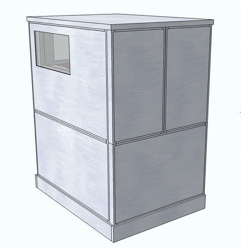
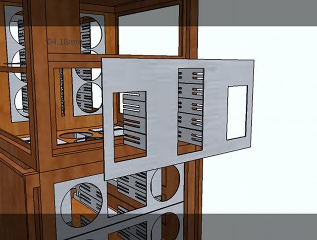
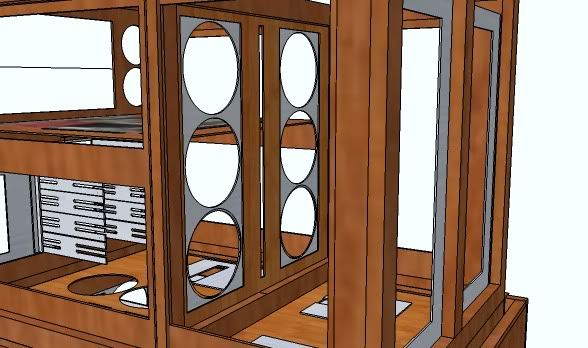
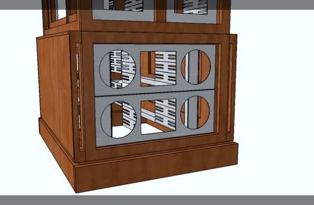
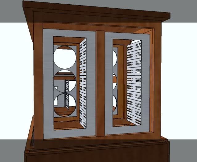
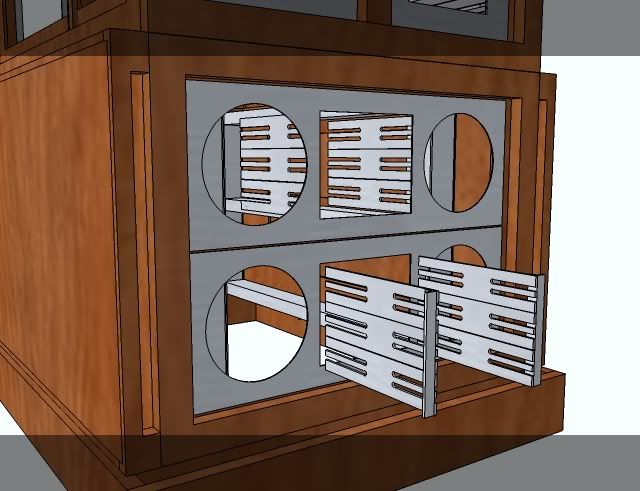
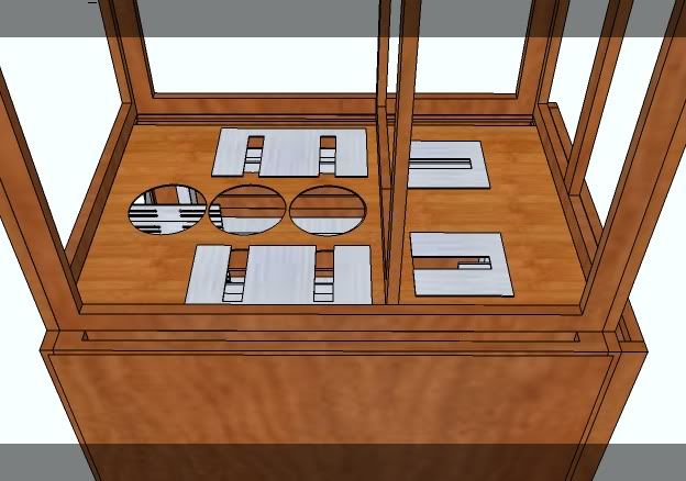
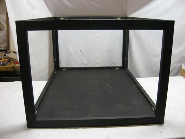
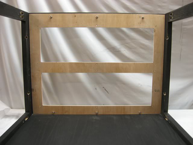
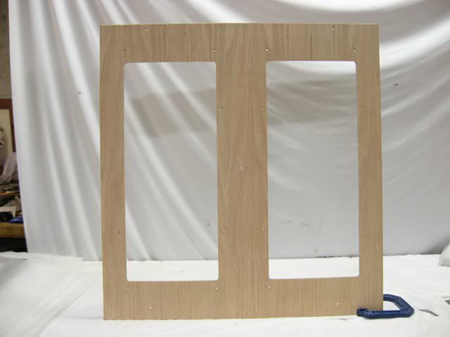
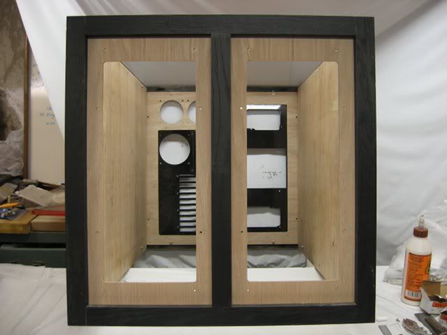
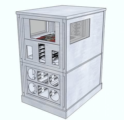
Note how the side panels are constructed as air ducts for supplying cool fresh air to the front and sides of the case:
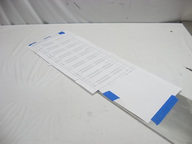
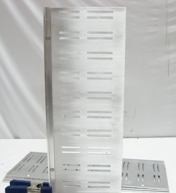
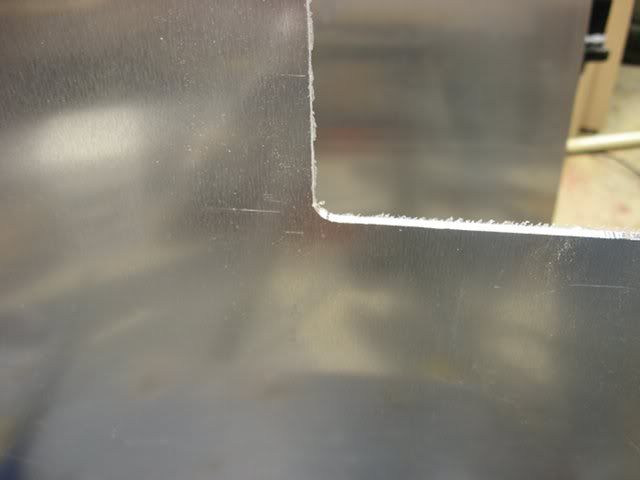
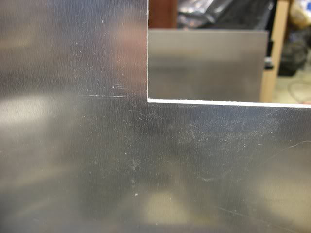
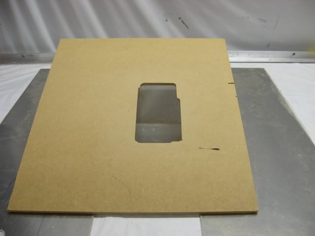
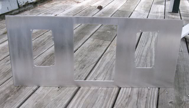
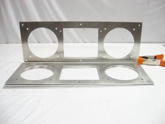
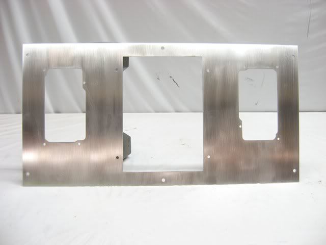
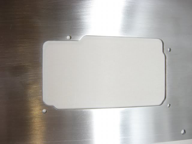
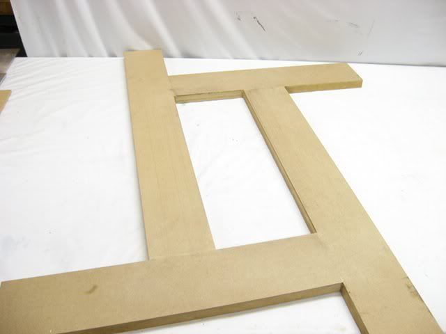
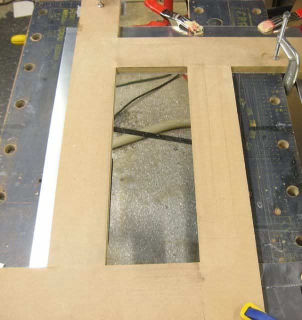
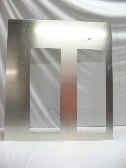
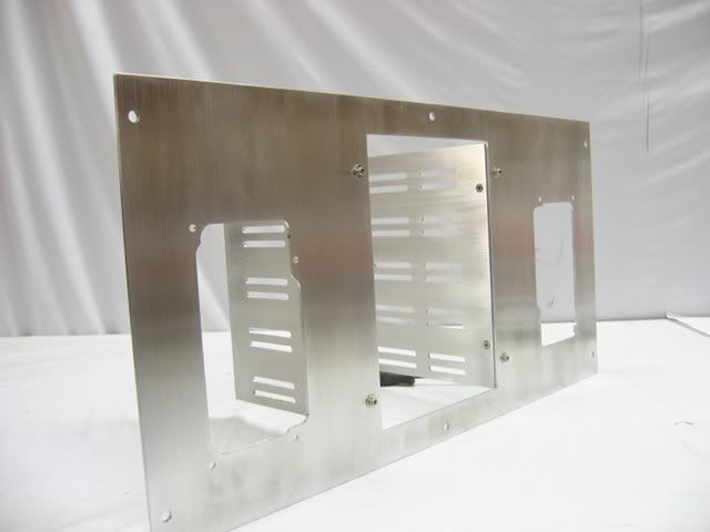
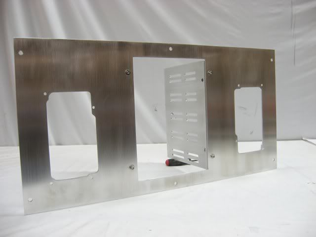
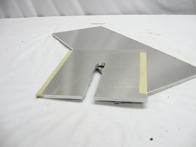
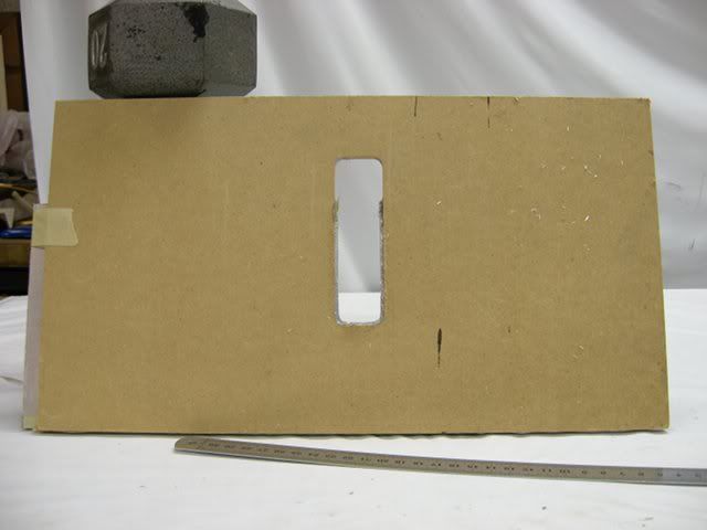
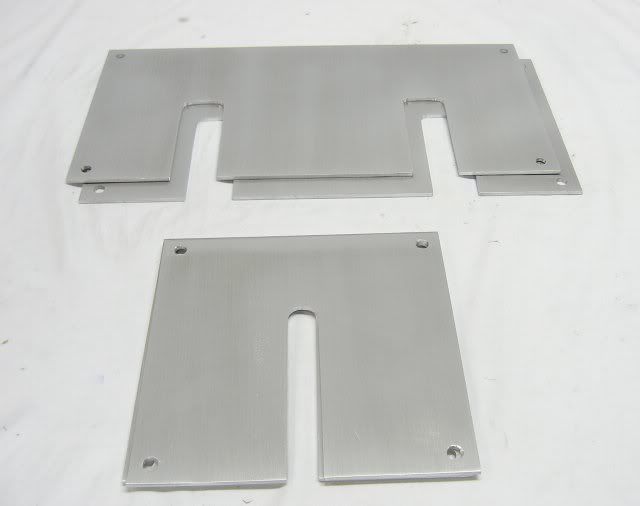
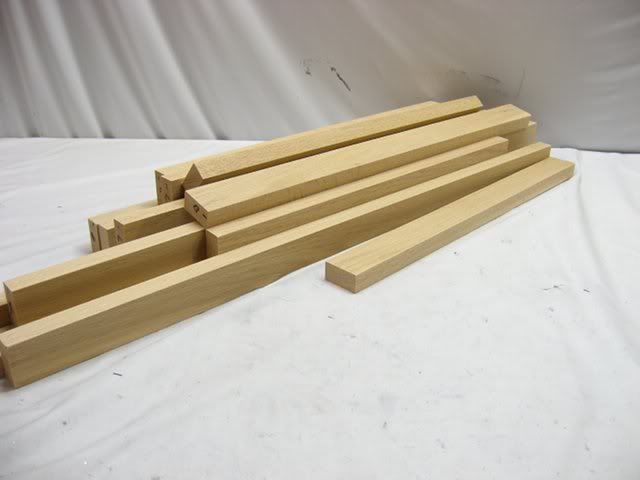
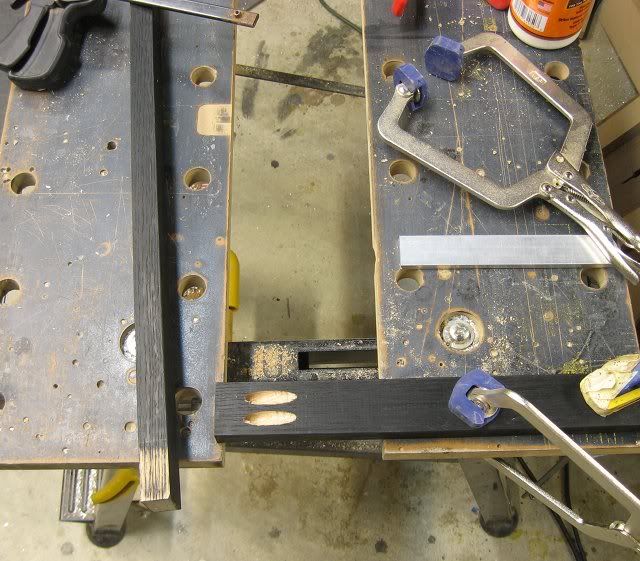
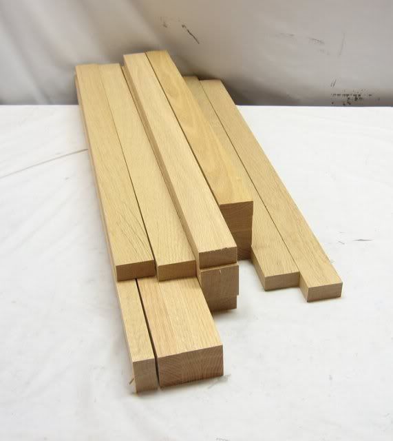
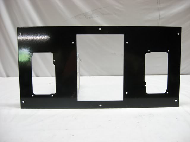
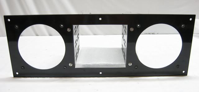
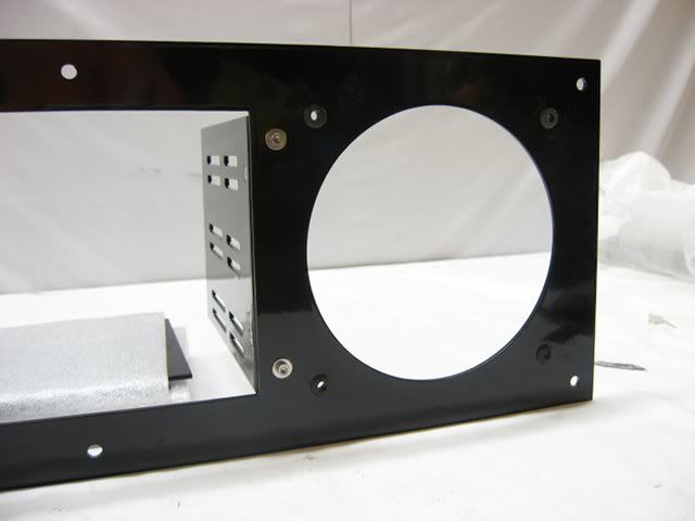
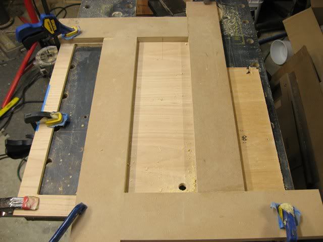
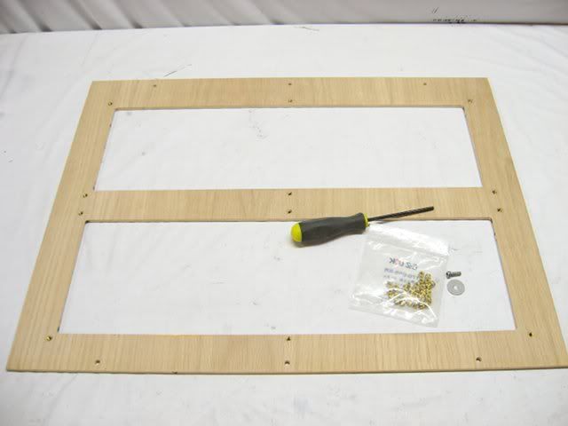
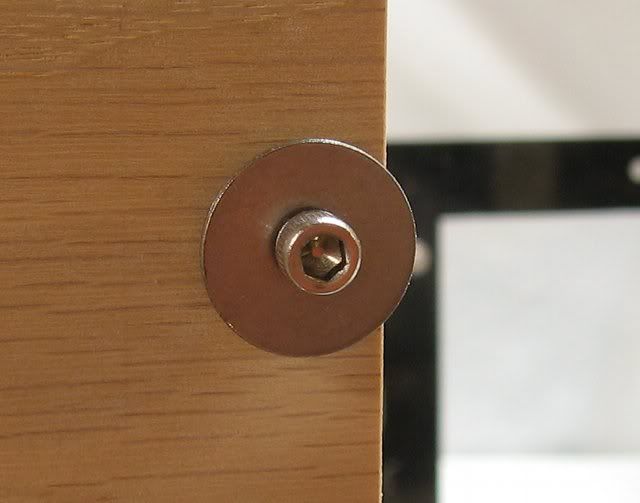
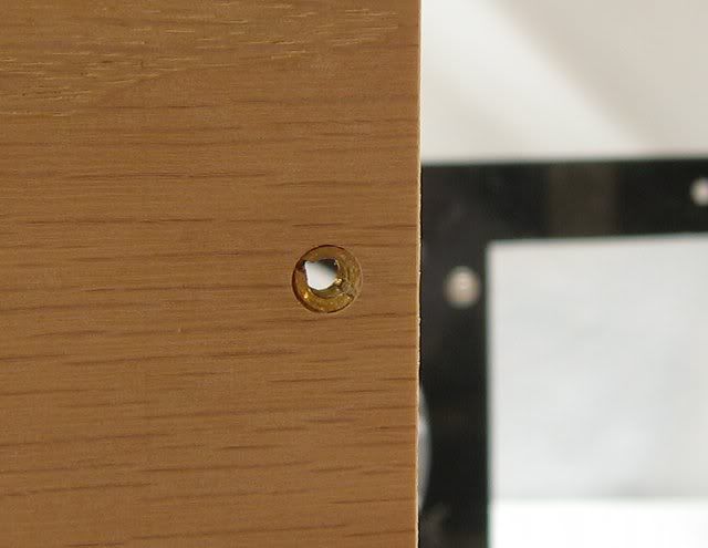
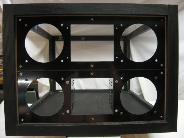
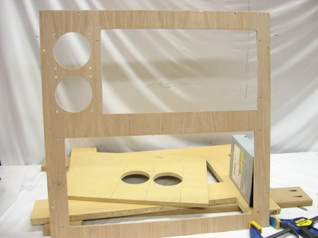
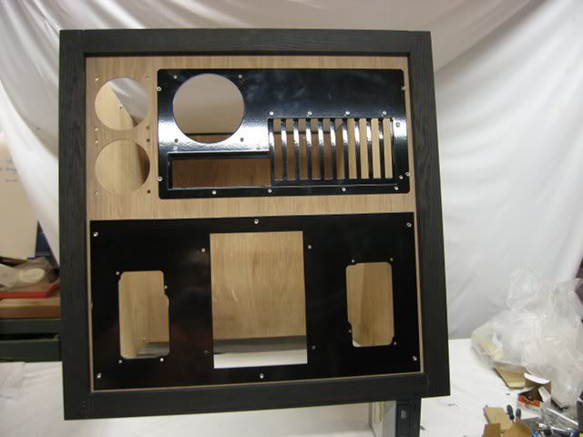
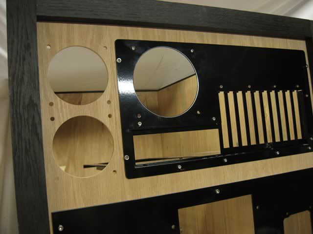
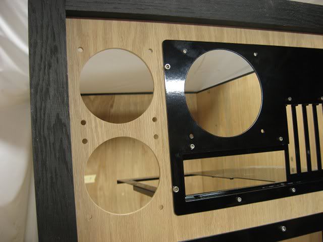
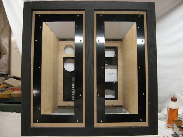
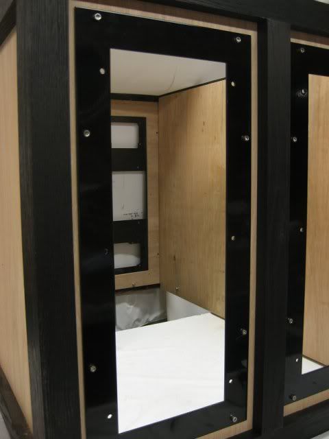
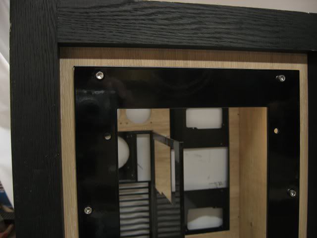
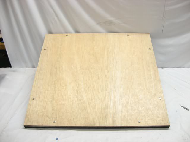
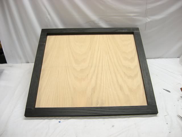
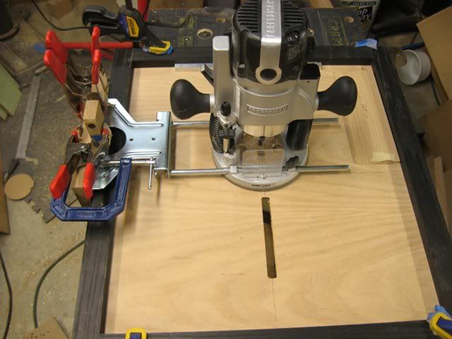
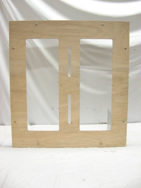
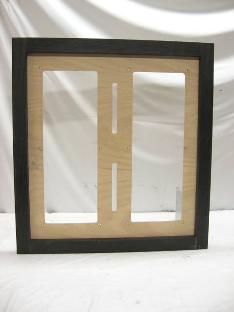
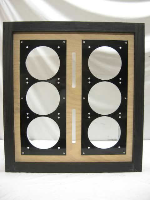
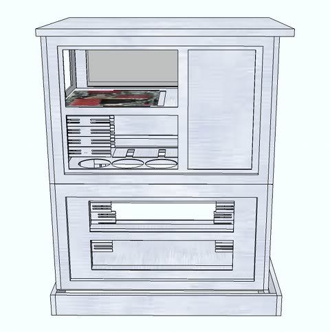
The walls will be constructed of 1.5-inch solid oak face frames with 5.2mm oak veneer plywood "panels" bolted to the inside of the frames and with aluminum "adapters" bolted to the front of the panels. The openings in the panels are sized to the largest pieces of hardware envisioned to be mounted in a particular location. The adapters could be exchanged with different adapters depending on what particular hardware is to be mounted in a panel opening.
Here are the specifications and some of the features of this case.
Physical Characteristics:
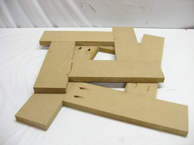
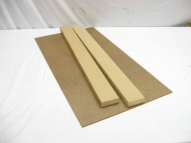
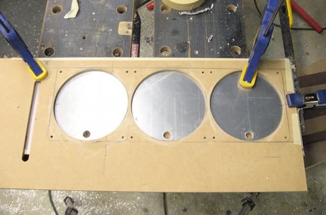
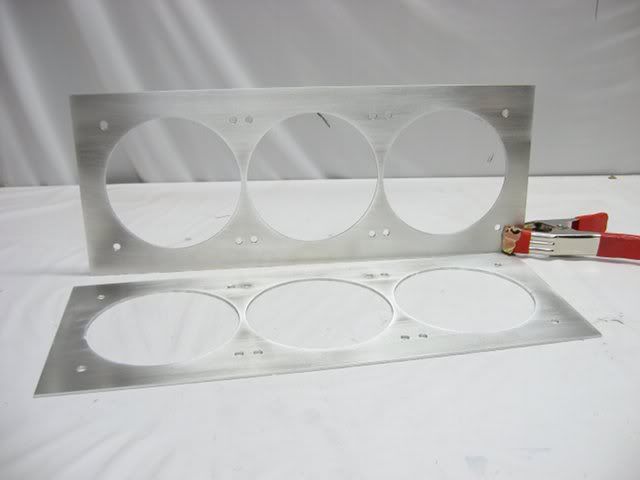
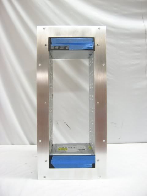
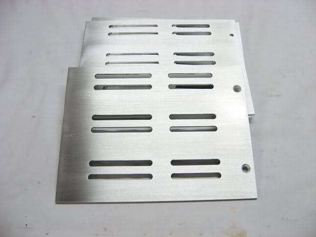
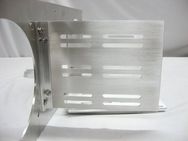
The bracket to hold the two Black Ice GTX 560 radiators is a simple affair, consisting of some aluminum 1x2-inch square tubing and channel.
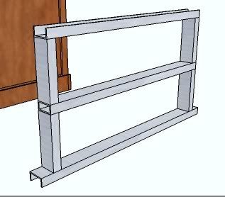
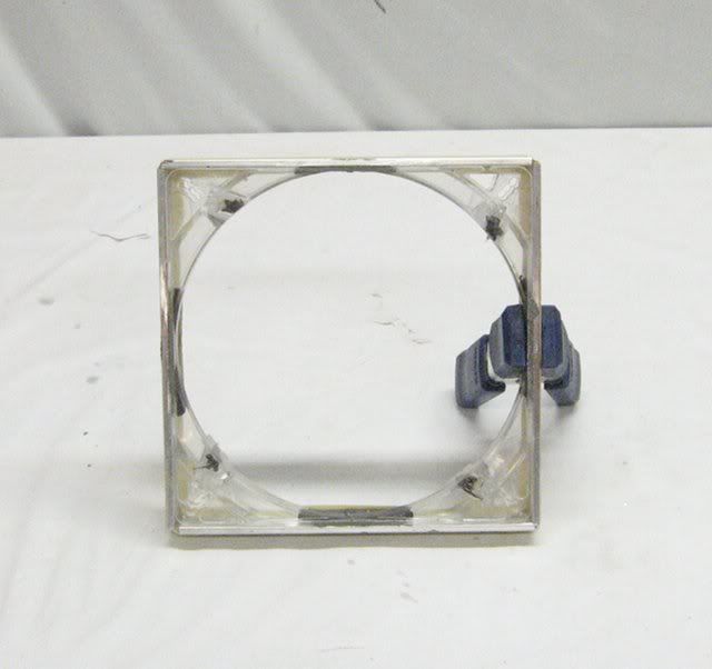
All of the pieces are held together with two long 1/4-inch threaded rods which act as clamps to hold everything together. The ~4mm tall acrylic bumpers get compressed down to ~2mm to keep the radiators in place:
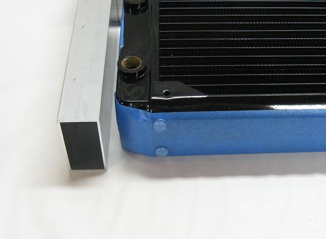
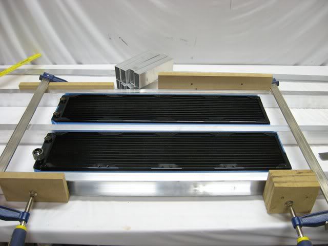
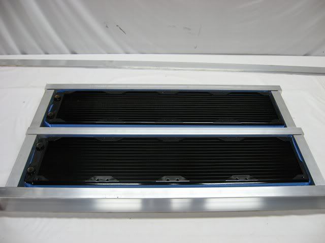
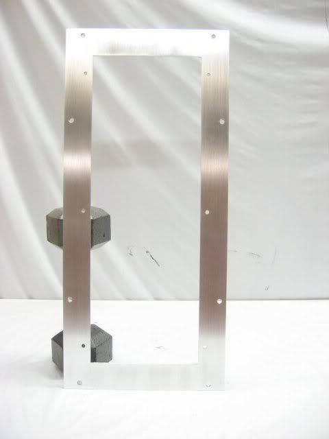
All of the aluminum bits will eventually be powder coated gloss black.
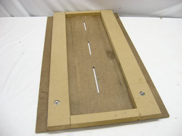
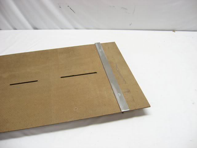
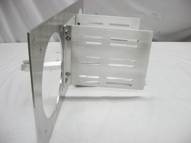
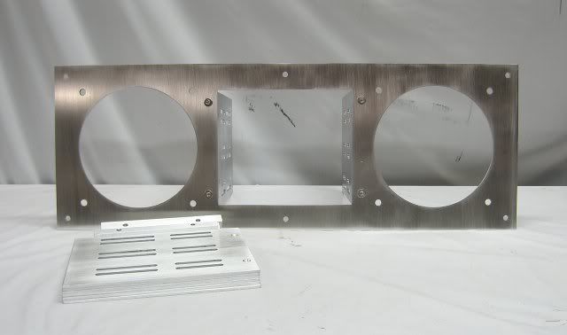
Note how the side panels are constructed as air ducts for supplying cool fresh air to the front and sides of the case:
The walls will be constructed of 1.5-inch solid oak face frames with 5.2mm oak veneer plywood "panels" bolted to the inside of the frames and with aluminum "adapters" bolted to the front of the panels. The openings in the panels are sized to the largest pieces of hardware envisioned to be mounted in a particular location. The adapters could be exchanged with different adapters depending on what particular hardware is to be mounted in a panel opening.
Here are the specifications and some of the features of this case.
Physical Characteristics:
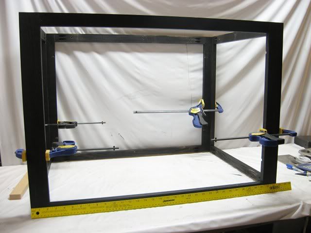
- External dimensions (HxWxD - inches): 44 x 26.5 x 35.5
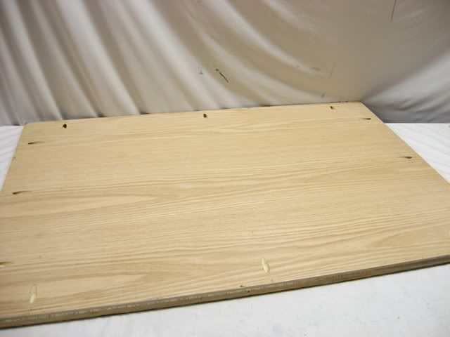
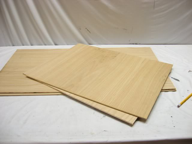
- 3/4-inch solid red oak, 3/4-inch and 5.2mm oak veneer plywood.
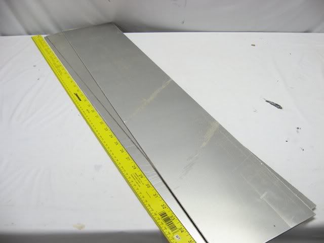
- .100-inch aluminum sheet and 1/8-inch aluminum angle, channel and rectangular tube.
- 1/8-inch clear acrylic.
- The side doors act as air ducts to supply fresh air from the bottom, top and back of the case to the front/sides.
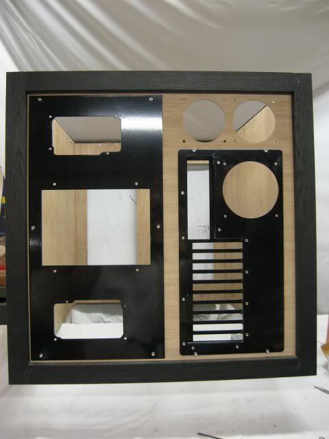
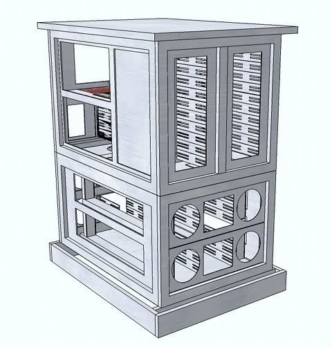
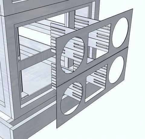
- Unique modular panel construction provides flexibility for the placement of drive bays, fans, power supplies, etc.
- Mounting locations for two power supplies.
- Air flow is: fresh air enters from the side/front and exhausts out the back.
- The bottom case has two custom radiator holders for mounting up to four 140x4 radiators.
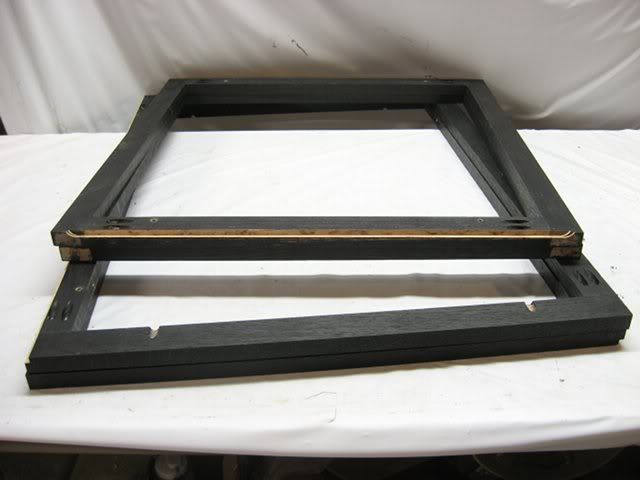
- The case is actually two separate cases bolted together.
- Removable ten slot motherboard tray.
- Motherboard tray can be mounted in a horizontal or vertical position.
- Powder coated aluminum.
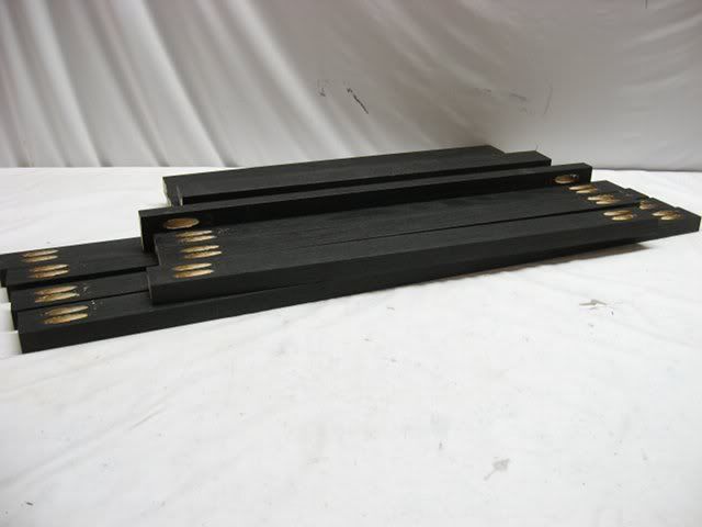
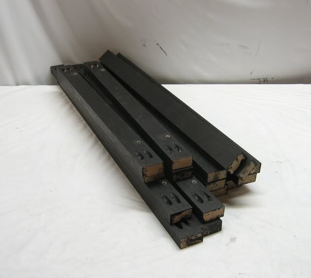
- Wood finished with black water-based stain and polyurethane.
The bracket to hold the two Black Ice GTX 560 radiators is a simple affair, consisting of some aluminum 1x2-inch square tubing and channel.
All of the pieces are held together with two long 1/4-inch threaded rods which act as clamps to hold everything together. The ~4mm tall acrylic bumpers get compressed down to ~2mm to keep the radiators in place:
All of the aluminum bits will eventually be powder coated gloss black.
")