Project: Beast III

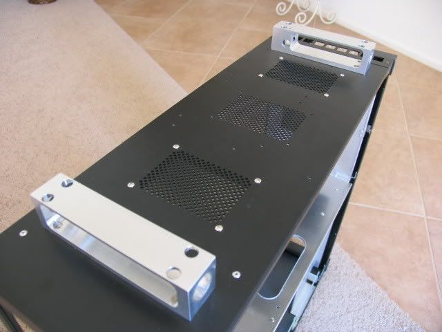
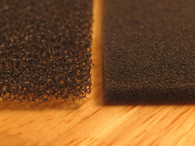
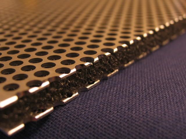
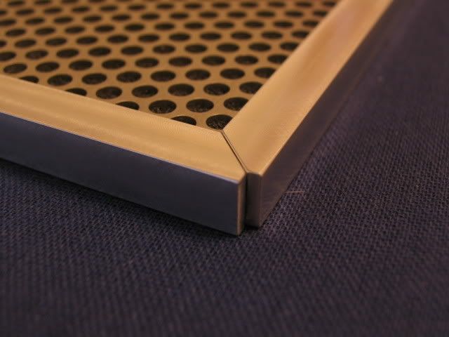
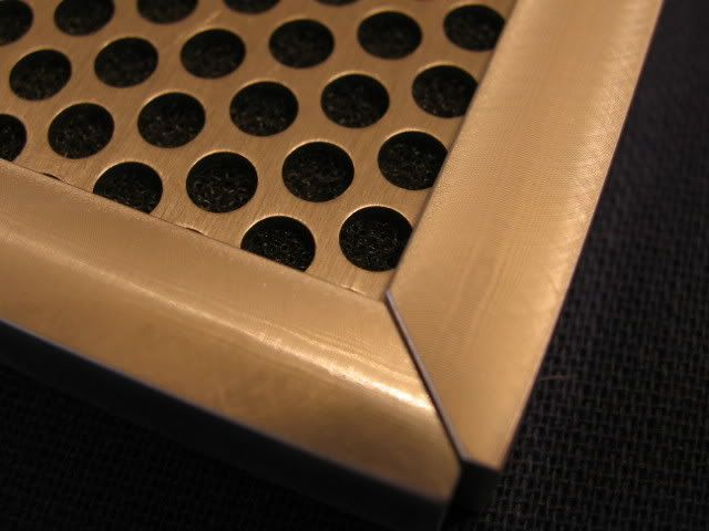
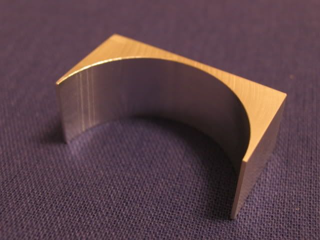
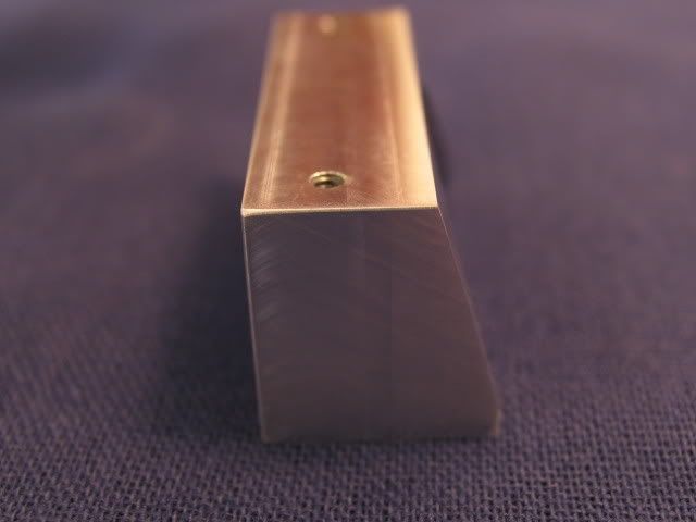
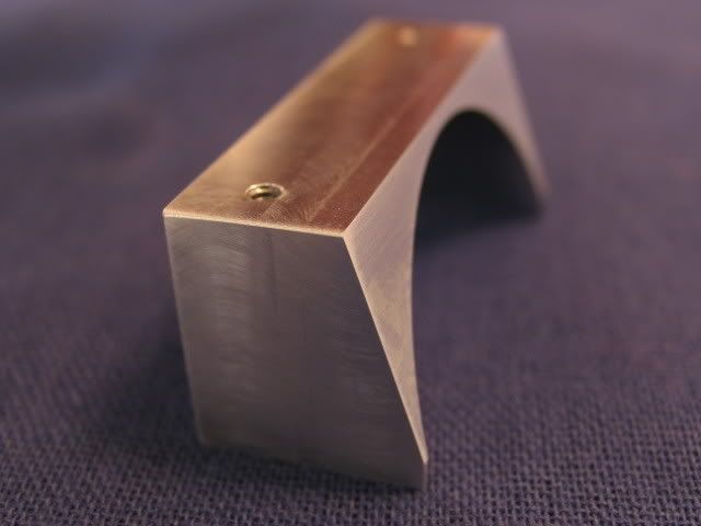
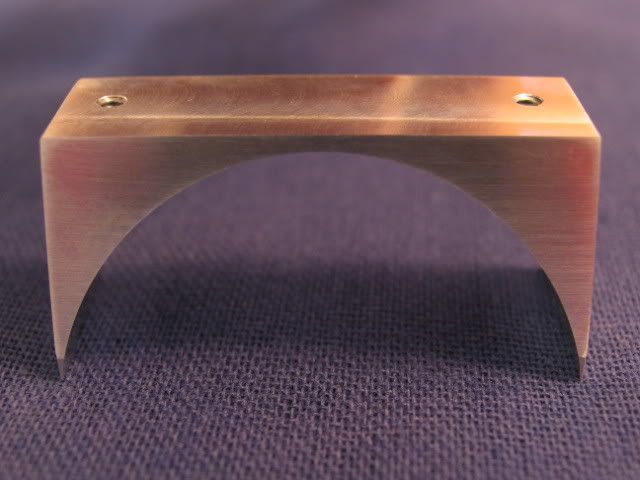
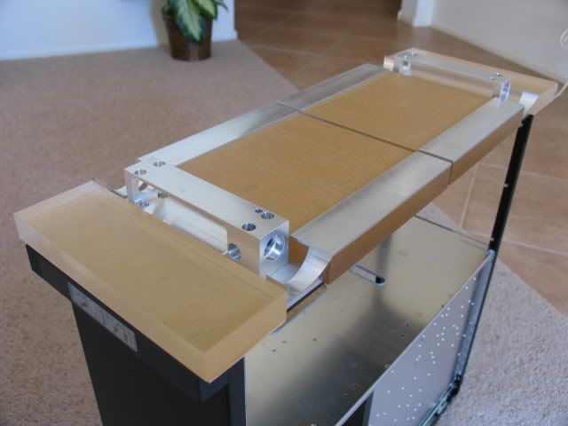
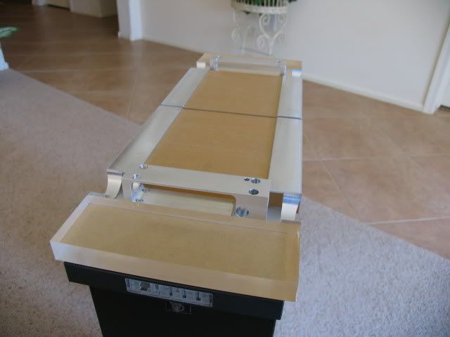
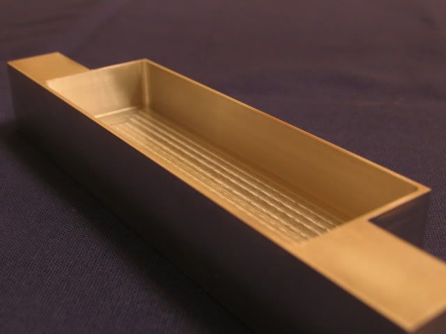
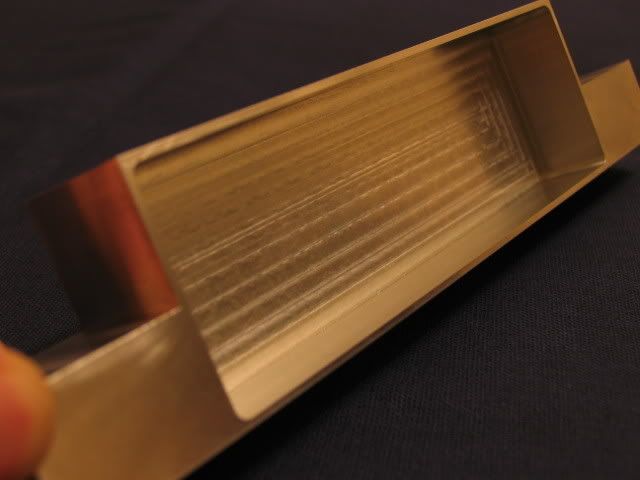
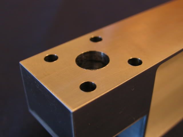
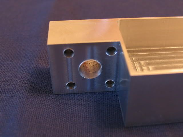
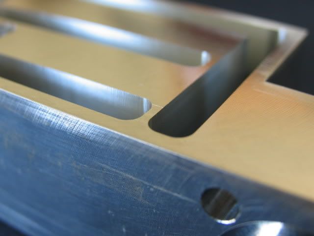
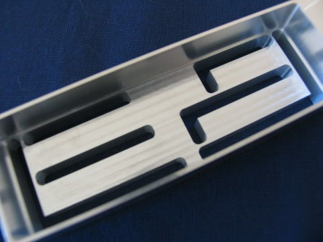
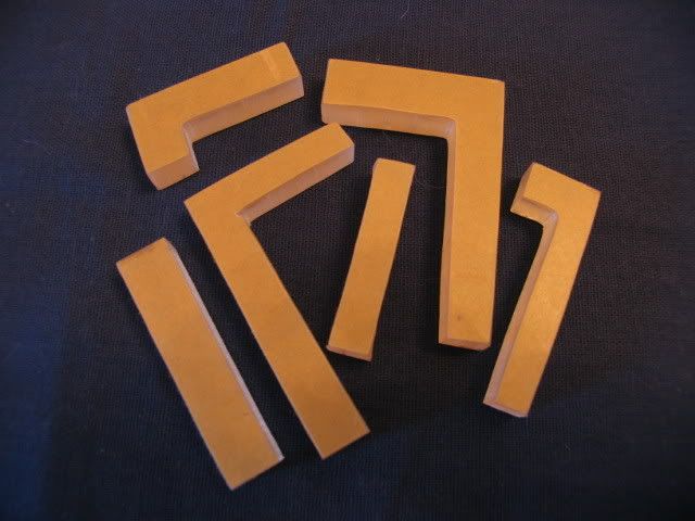
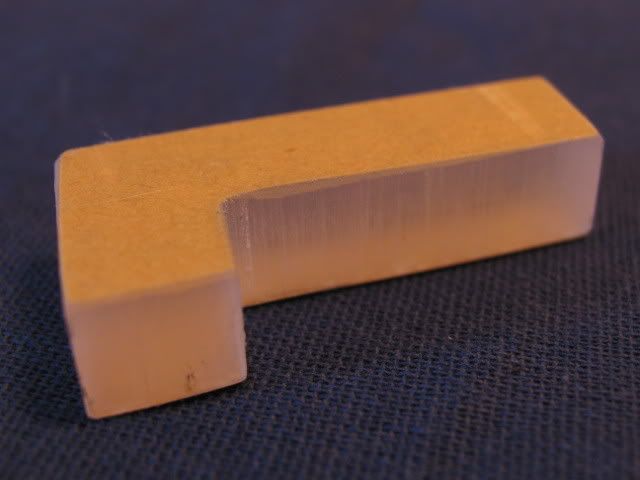
Cool. I was wondering if you were going to have some components on individual cooling systems (like the hard drives, or RAM for example). If the cooling capacity for the whole system is good enough (and it looks like it probably would be) then having the hard drive tied in to the GPU, CPU etc probably won't be an issue.
 
imagine the complete thing with all components and water it will weigh like a ton.
 
You've undoubtedly put the most work and time into a case I have ever seen, same with probably everybody else... Unless these people have seen you, hehe.

/subscribed

Anxiously awaiting outcome... Hey maybe you'll have it done for my Birthday? Same time as Christmas '07 ;)
On a side note I'm not too sure a case grip will hold all that for going to LAN parties.:eek:
 
Dude u must be living your dream lol. Your so lucky to have a machine shop like that to create this beast! btw what kind of camera do u have, cos those are crystal clear pics that i couldnt do with my 6mp 3x zoom casio lmfao.
 
DAAAAAAAAAMN! That is one hell of mod and I like it a lot!
jawdrop.gif
 
It’s been a while since I last posted a comment as I have just been enjoying all the work.
OH MY GOD MAN! :eek:
Steven this is amazing.
You are on my list of best mods on [H] of all time for sure!
The thing that makes this so awesome is the fact that almost everything is a Rad!!! The B3 on the door looks like artwork but in fact it’s a RAD!!!! OMG! The coiled tubes, look like part of the cases charm… BUT THEY TOO ARE RADS! :eek:

Then you have these nice touches such as the milled “BEAST” and the really nice looking “III” and the [H]ardOCP with the mirror backing. This case is going to out class anything you put inside it. At this point you are going to need to fill the case with a super computer to outdo the amazement factor of the case.
Kudos don’t cut it, I am going to Fed Ex you a case of Canadian Beer! :)

Keep up the great work I am really impressed! ;)
 
there is no words to explain how beautiful this case is!! keep up the great job :D :D :D !!!

i have a 2 personal questions for you.
but you don't have to answer it if you don't want to...

what do you do for a living !?
'cause dam man you do some of the finest works i have ever seen :)

can you give us a look to your workshop and tools?
to see the tools who made the BEAST ! :D
 
HOLY MOTHER OF GOD !!!

What kind of machines do you use to make all these things? What kind of stuff you have to tap the plexi for instance???????

Here's my question: what do you think? Is it possible to build an acrylic case with side panels tapped and folded together? I mean do I need to use additional acrylic cubes with some tapped inserts to screw the panels together or should I just buy 10mm panels and tap them in all corners???
 
I just said "holy shit, this is awesome" out loud. And not because of the shock factor (I thought the dark blade from the other forum was cool, but it looks crazy/overdone), but because of the workmanship and attention to detail.

If you're not doing this for a living, you should seriously consider starting your own machinist company, or whatever lucrative fields machinists can take part in. :D

Subscribed!
 
[M]artini69;1031035029 said:
Dude u must be living your dream lol. Your so lucky to have a machine shop like that to create this beast! btw what kind of camera do u have, cos those are crystal clear pics that i couldnt do with my 6mp 3x zoom casio lmfao.

I use a canon Pro 1 mounted on a tri-pod. The macro mode on this thing is the best. I would have to spend like $400.00 on a good macro lense for my Rebel XT to equal these shots.
 
there is no words to explain how beautiful this case is!! keep up the great job :D :D :D !!!

i have a 2 personal questions for you.
but you don't have to answer it if you don't want to...

what do you do for a living !?
'cause dam man you do some of the finest works i have ever seen :)

can you give us a look to your workshop and tools?
to see the tools who made the BEAST ! :D

I'll answer. First, I'm a machinist (my second job is with the Air Force Reserve), second, I suppose I could take some pics of the shop and of my tools. Most of my tools can be found on Mitutoyo's website though. In my next post there are a couple shots of a boring head and a custom modified end mill made to cut o-ring grooves (with part in vise cinched to mill table etc.)
 
HOLY MOTHER OF GOD !!!

What kind of machines do you use to make all these things? What kind of stuff you have to tap the plexi for instance???????

Here's my question: what do you think? Is it possible to build an acrylic case with side panels tapped and folded together? I mean do I need to use additional acrylic cubes with some tapped inserts to screw the panels together or should I just buy 10mm panels and tap them in all corners???

98% of all this work has been done a manual mill and manual lathe. Some of the parts for the 'Radivor' were snuck in on one of our CNC lathes.

As far as your plexi case, I suppose it all depends on how thick the plexi is. I would need specific details on how, what, and where.
 
I just said "holy shit, this is awesome" out loud. And not because of the shock factor (I thought the dark blade from the other forum was cool, but it looks crazy/overdone), but because of the workmanship and attention to detail.

If you're not doing this for a living, you should seriously consider starting your own machinist company, or whatever lucrative fields machinists can take part in. :D

Subscribed!

If I had the money I would open my own company. I doubt I would turn a profit unless I could cater to people with LOTS of $$$ and the patience to wait without whining.
 
Yes the rumors are true, I'm still alive.

And thanks for all the nice comments! It's you people that keep me going!

In addition to Beast III, I have started Beast 2.5 (see post). These two projects, working full time and going to school are keeping me uber busy.

Luckily, I have yet to burn out. Good for you avid post readers too!

On with the post.

I was thinking about how heavy this thing is getting and was scoping the bottom of the case where the wheel housings go. I'm starting to think that as tough as Lian-Li cases are, that thin aluminum is going to really flex when I'm done with this.

So the wheels began to churn and I came up with the idea to re-enfoce the bottom by distributing the weight over a larger area. One thing led to another and now I'm incorporating air filters, lights, bling, and even ad space.

Here are some shots of the bottom with the wheel housings
bottomassy001.jpg

bottomassy002.jpg

bottomassy003.jpg


My first thought was to add a 1” thick piece of plexiglass to the bottom (spanning the width by the depth). This idea was shot when I realized that a piece of plexi 8.5” wide by 23.6” inches deep was going to be nearly impossible to create with the limited travel of the milling machines at my disposal.

So I decided to split the plexi into 4 pieces. Here is the front section
frontbottomplexi001.jpg


Here are the middle sections
midbottomplexi001.jpg


And the back section
backbottomplexi001.jpg


In between the section are the spanners which are as wide as the case (.25 thick by 1.5 by 8.?)
spanner001.jpg


This aluminum was ordered ground to .250” thick. Expensive stuff but worth it!
spanner002.jpg


In the middle sections I’m going to add some lights and air filters (made by yours truly)
Here is a shot of the perforated aluminum I’m using for the filters
filtermesh001.jpg


Close-up (these are yet to be machined to size)
filtermesh002.jpg


To hold these holy plates (pun intended) are some rails. First step is to square up the material
filterrail001.jpg

filterrail002.jpg

filterrail003.jpg


I then rough milled a slot in them
filterrail004.jpg


Close-up
filterrail005.jpg


Check those burrs!
filterrail006.jpg


Here are the slots and angles finished
filterrail007.jpg

filterrail008.jpg


The lot (two middle sections = two filters = four rails per)
filterrail009.jpg


I don’t have the brackets that are going to join these rails done yet, but here is what it will look like
filterrail010.jpg


On the mesh
filterrail011.jpg


Here is how it will butt up inside the slot
filterrail012.jpg


Inside these filters will be some foam. I couldn’t decide on which density I should get so I got both
filterfoam001.jpg


30 pores per inch is one the left, 60 pores per inch on the right
filterfoam002.jpg


The sandwich
filterrail013.jpg


Here is a shot of the corner to give you an idea
filterrail015.jpg


Close-up
filterrail014.jpg


To affix these filters to the bottom plexi pieces I made up some rails (later pics will clarify)
bottomtrim001.jpg


This aluminum is 1/8” thick and I’m cutting it down to .100” thick. Not an easy task. The material likes to vibrate and you get this horrible wavy pattern in it.
The lot before cutting
bottomtrim002.jpg


First cut
bottomtrim003.jpg


Second
bottomtrim004.jpg


The lot
bottomtrim005.jpg


Since the spanner pieces are as wide as the case, I needed to extend the wheels out a bit. And in doing so I came up with a brilliant plan to add some fenders to the wheels. These next pieces are the gap fill pieces between the spanners and the actual fenders (not yet created)
First, the block
fender001.jpg


Next, some tapped holes to hold it place (also used by me to actually make them)
fender002.jpg


Now for the arc
fender003.jpg

fender004.jpg


The angle seen here will be repeated on the bottom plexi pieces
fender005.jpg

fender006.jpg

fender007.jpg

fender008.jpg


The land (flat) there is only .010” of an inch wide
fender009.jpg


The lot
fender010.jpg


Here is a rough placement of where all these pieces are going
bottomassy004.jpg

bottomassy005.jpg


Close-up
bottomassy006.jpg


If you have been keeping up with the thread, you’ll know that I planned to have two hose barbs at the bottom of the PSU shroud to feed and return the coils. Well I scrapped the barbs and came up with a better plan. I’m going to use the back bottom plexi as a router for the feed and return and incorporate a spanner. The spanner was originally going to be a block of aluminum .75 “ x 1.20” x width of PSU shroud. But I came up with another crazy bling idea.
First the block
backb3alum001.jpg


Cut-outs
backb3alum002.jpg

backb3alum003.jpg


I then added this pocket in the back for some 4” CCFL’s (red)
backb3alum004.jpg

backb3alum005.jpg


Here is the feed hole and the screw holes roughed in
backb3alum006.jpg

backb3alum007.jpg


Here are the screw and thru holes finished and the o-ring groove added
backb3alum008.jpg


Top
backb3alum009.jpg


o-ring
backb3alum010.jpg


Here is a shot of the process for machining the o-ring
backb3mill001.jpg


I used a standard boring head and a custom ground .5” diameter end mill to cut the groove. The width of the cutter was about .080” wide and the width of the o-ring groove was .122” so I needed a way to be able to move the cutter (hence the boring head)
backb3mill002.jpg


Here is a shot of the pattern of the B3 (bling at it’s finest)
backb3alum011.jpg

backb3alum012.jpg


My flub
backb3alum013.jpg


Other flub (this one is a little hard to see. There is a little cut from slot to slot .002 deep)
backb3alum014.jpg


Pocket shot
backb3alum015.jpg


Inside these slots are going to be some plexi glass custom fit to the slots. I printed off some templates to help rough cut the pieces
backB3plexi000.jpg

backB3plexi001.jpg


Close-up (this material is about .45” thick)
backB3plexi002.jpg


One done
backb3plexi003.jpg


More
backb3plexi004.jpg


A few more
backb3plexi005.jpg


And still some more
backb3plexi006.jpg


Here is a shot of the plexi sitting on top of the slots (after anodize, these plexi pieces will be modified and press fit into the slots)
backb3alum016.jpg

backb3alum017.jpg


Another flub (plexi is really tricky to work with)
backb3alum018.jpg

backb3alum019.jpg


More views (imagine the front of the plexi flush with the aluminum)
backb3plexi007.jpg

backb3plexi008.jpg


This is where this back B3 piece is going. PSU shroud
backb3assy001.jpg

backb3assy002.jpg


Back bottom plexi
backb3assy003.jpg


Imagine a slot cut into the plexi for the B3 piece
backb3assy004.jpg


This is all I have done for Beast III so far. I hope you enjoyed my machinist pron!!!

On a sad note, the completion date for Beast III has been pushed back to ‘when I get her done’. The pressure of having to meet ’07 x-mas was killing me. It wasn’t going to happen. But hey, you’ll get more pron (I mean posts) this way! LOL.

Look for another post on Beast 2.5 soon. I have done some more work there as well.
 
Use the 30 pore per inch foam, it looks to be about what the centurion 5 uses, and does a great job.
 
I think I would pay money to make machinings as nice as your "flubs" :p
 
this is the best mod/worklog on [H]

this guy should have his own title next to his alias

like [H]machinest
 
[H]machinest

Definitely...I am simply in awe.. Your skills and creativity are second to none man...

And I'm completely serious when I second the [H]Machinest... I'm almost happy that the completion date has been moved... I check this thread daily for updates, it really makes my day when there is a new one!
 
Quick question, are you sponsored by any of the modding companies?

If not, then I suggest you send them some links to your work.
 
98% of all this work has been done a manual mill and manual lathe. Some of the parts for the 'Radivor' were snuck in on one of our CNC lathes.

As far as your plexi case, I suppose it all depends on how thick the plexi is. I would need specific details on how, what, and where.


JESUS! I just saw your last post... you're a magician! all these parts looks SO professional!! All the cuts drills... amazing..

About my question: here's a link to my worklog - well, now it's only an idea, I didn't start it yet : http://www.sudhian.com/index.php?/forums/viewthread/98228/P30/

Very simply - it will be a cube - 300x300x300, I wnated to build it based on 10mm acrylic panels, drill them and tap (thread) all panels to make possible use only a screws to fold them together. Onother easier idea is to cut some small 20x20x20mm acrylic cubes and drill them and put small tapped inserts for every panel - explained in my worklog, last page (3).
What do you think? maybe easier would be use that cubes and then 5mm panels?
 
(after anodize, these plexi pieces will be modified and press fit into the slots)
Be careful press-fitting plexi-glass! We press all kinds of metals into all kinds of plastics, and if the fit is too tight things DO get ugly. You obviously know what you're doing, but it'll make me feel better to state a suggestion, however obvious it might be.

Looking at pictures like this one:
backb3alum016.jpg

One might think that you plan to press the plexi just like that. However, if the fit is too tight, you may have plexi shavings on the face of the logo.

I suggest chamfering the holes on the inside of the 'pocket':
backb3alum015.jpg

and pressing the plexi in from the back. This way, any material that is sheared off will not be gumming up the front. A small chamfer on the plexi wouldn't hurt anything, but shouldn't be necessary if you want a flush front surface.

I feel better now. Oh yeah, and your work is amazing!
 
Back
Top