Navigation
Install the app
How to install the app on iOS
Follow along with the video below to see how to install our site as a web app on your home screen.
Note: This feature may not be available in some browsers.
More options
You are using an out of date browser. It may not display this or other websites correctly.
You should upgrade or use an alternative browser.
You should upgrade or use an alternative browser.
Project: Beast 2.5
- Thread starter Stevennoland
- Start date
more more more more more
yes, more more more more
GhengisKhan
Supreme [H]ardness
- Joined
- May 16, 2005
- Messages
- 7,808
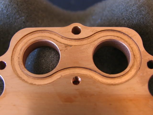
damn, I wish I had access to a CNC. Quick question about that southbridge block though... with the angled access holes that you have, won't the water just flow down one and right back up the other? That looks like a lot of dead space for the water to just sit around heating up and not moving.
You know, people have lives outside of casemodding. I doubt he quit this mod, just that things get busy sometimes.
in that case, bump!
You know, people have lives outside of case modding.
When did this start happening?

Stevennoland
Limp Gawd
- Joined
- Jan 5, 2006
- Messages
- 418
Back with a little more.
Yea, I have been busy. On with the update!
For those of you who own an 8800GTX and DangerDen H2O block to cool it, the insides:
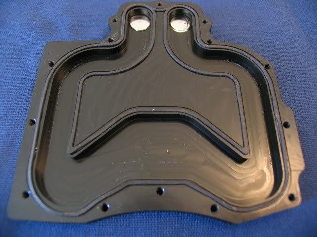
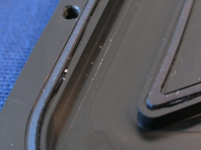
Some of these delrin burrs are totally unacceptable
The sealing gasket is also nothing to write home about (I thought for sure it would be rounded). I can see why some are blowing them out
More
Naked
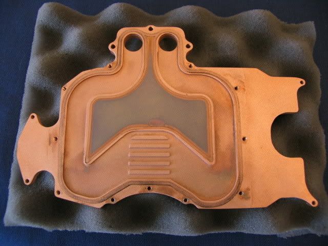
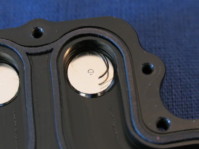
Close-up
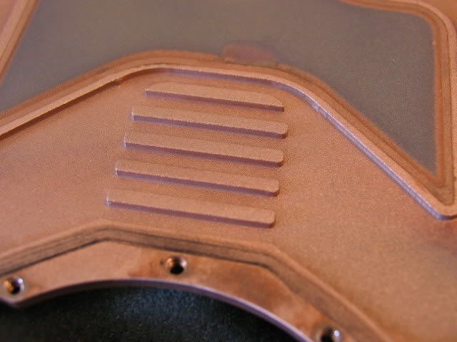
Looks like it was cast and then bead blasted
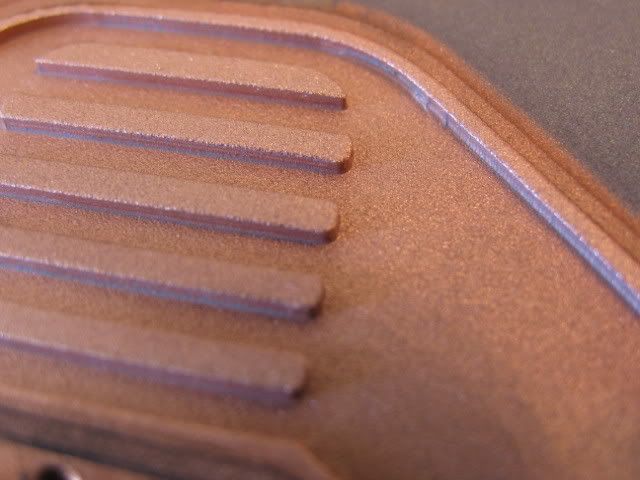
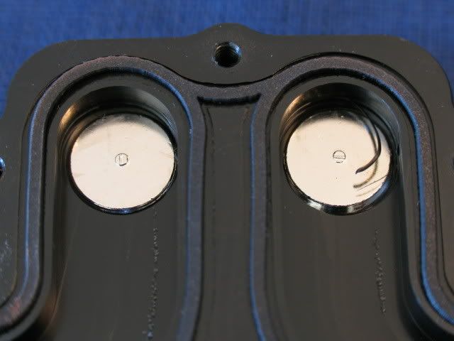
One more
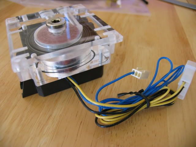
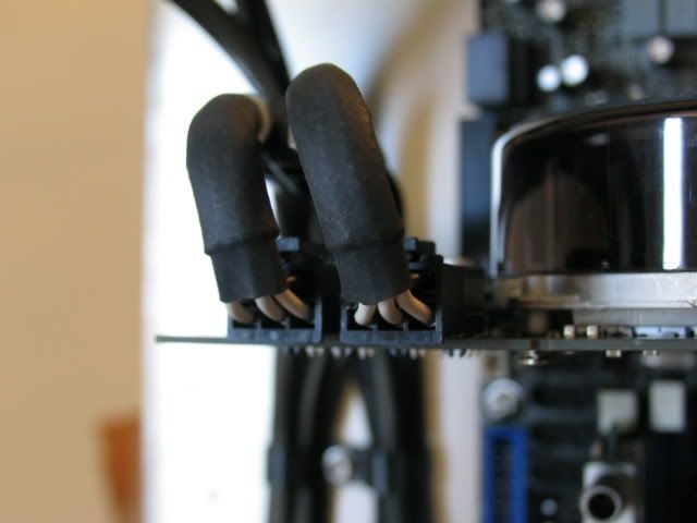
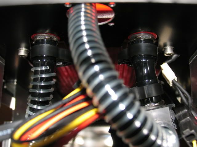
Here is the wiring of the pumps, needs some Steve magic
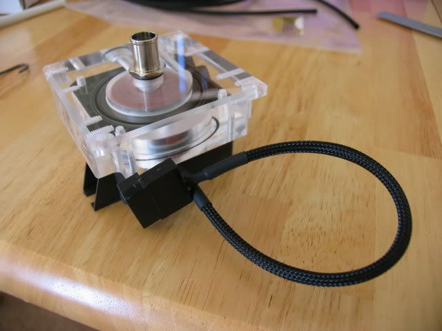
Abracadabra
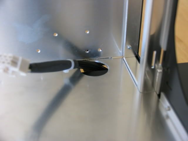
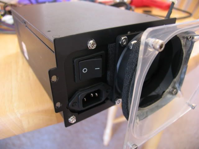
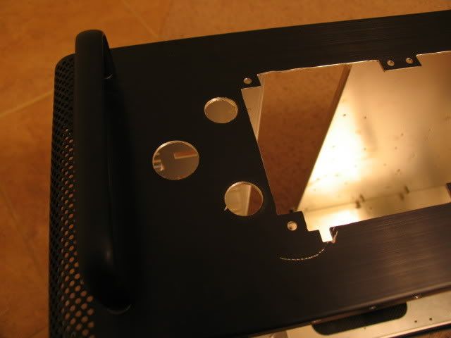
I added this hole for the 8-pin power plug (right where it is on the mobo)
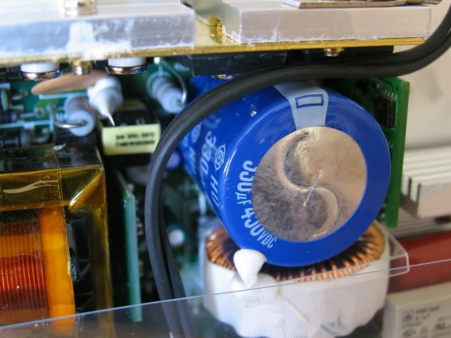
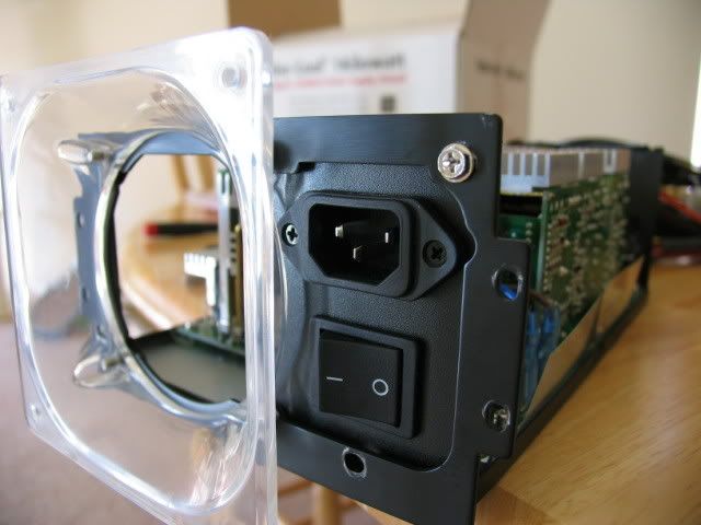
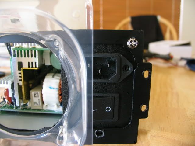
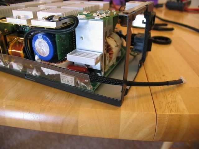
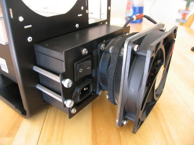
I had read the fan on the PC Power and Cooling 1KW Turbo cool was loud, so I figured that modding it to a 120mm would be a cool idea (so I initially thought).
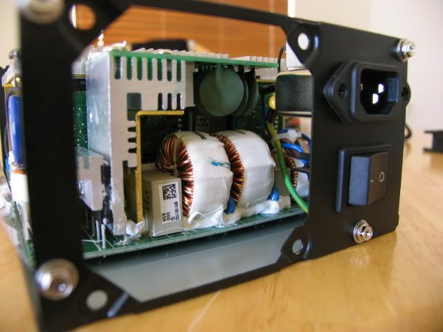
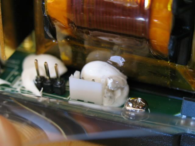
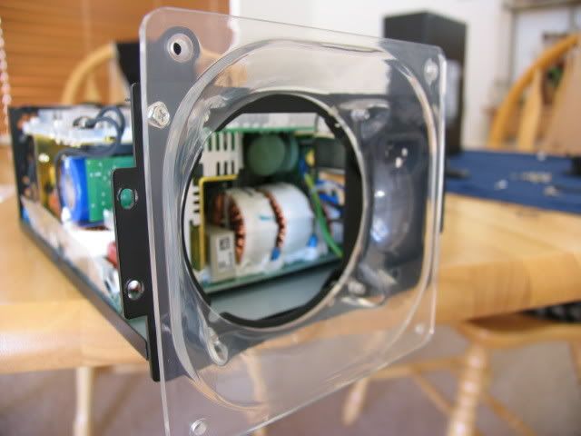
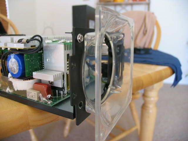
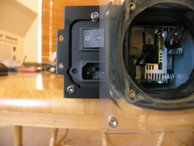
Here are some shots of the innards, here you can see just how close the fan is
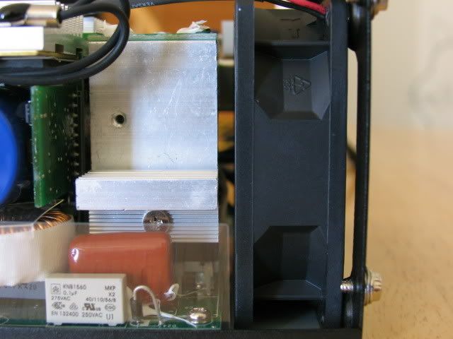
No fan
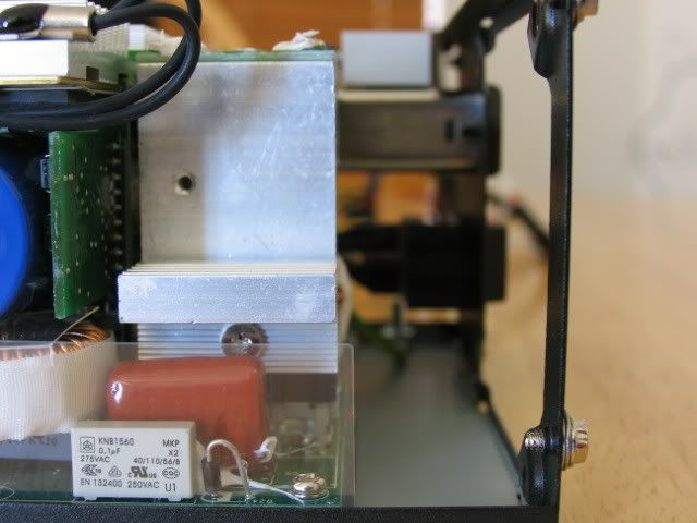
The loud stock fan
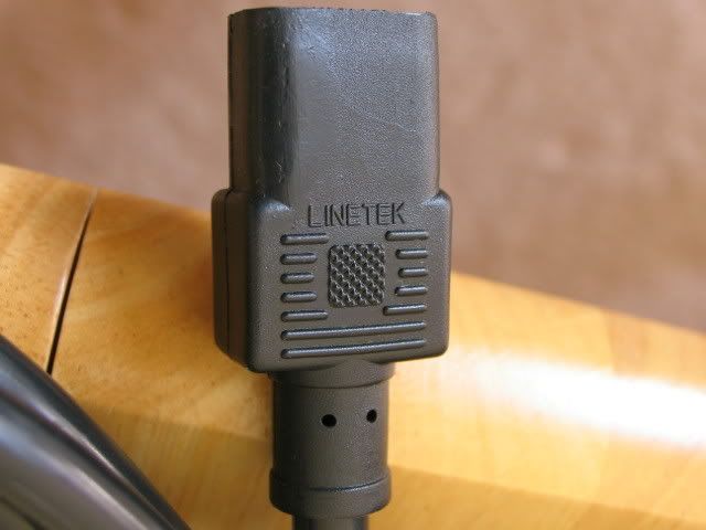
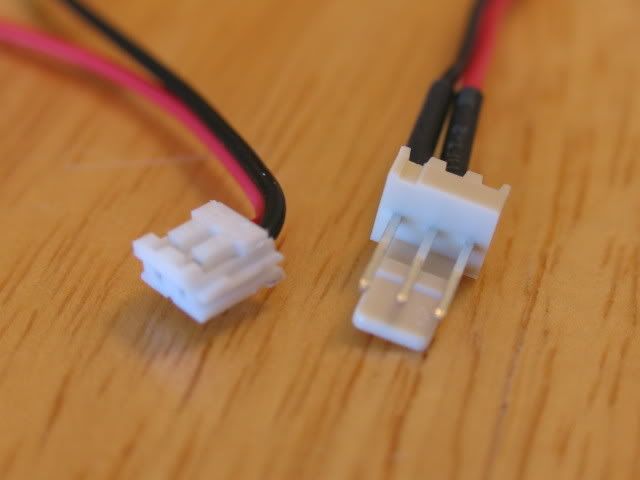
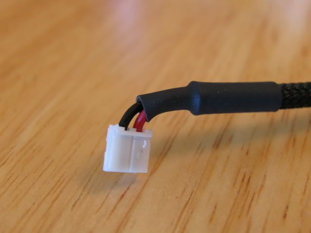
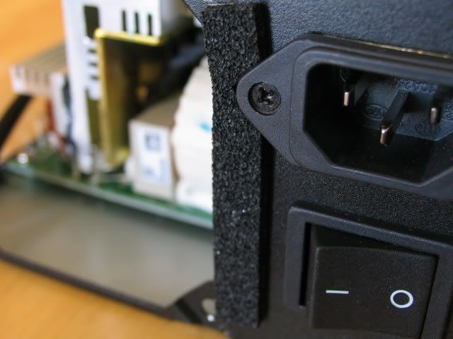
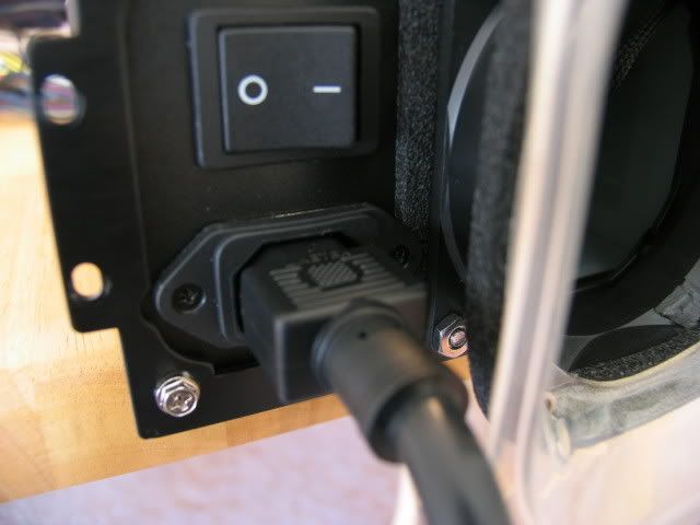
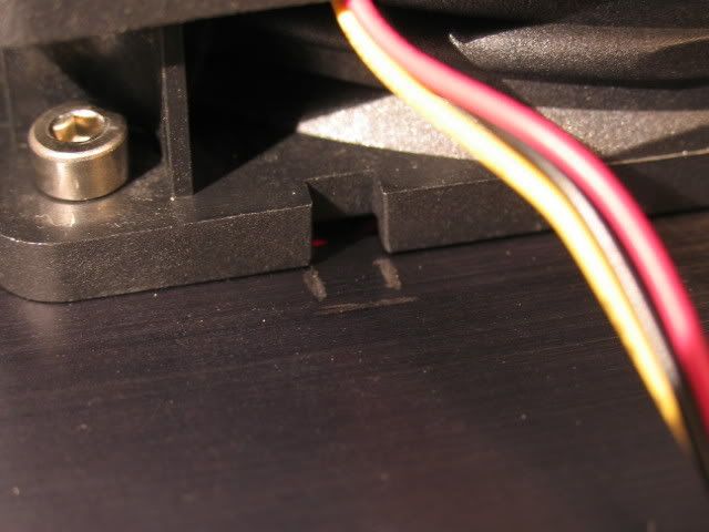
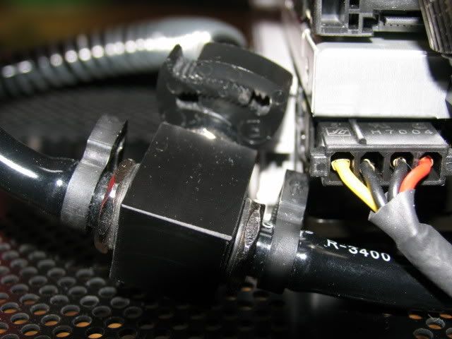
They couldnt use a standard connector (grrrrr)
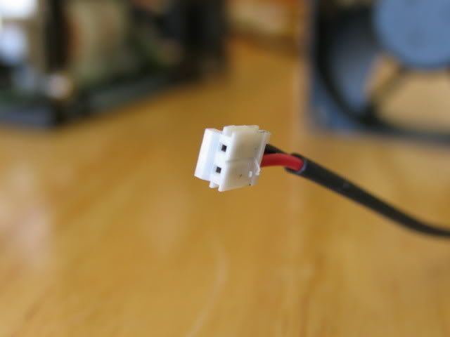
Home of the bastard connector
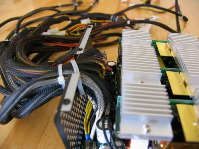
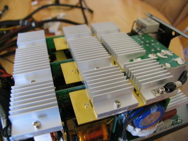
Some other misc. shots
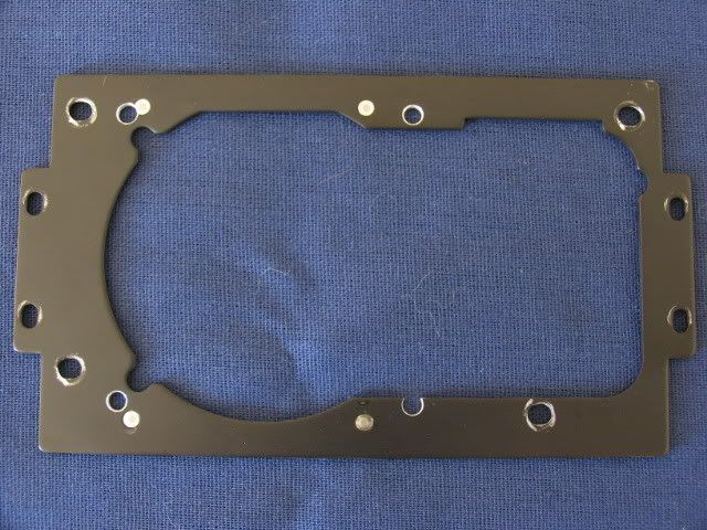
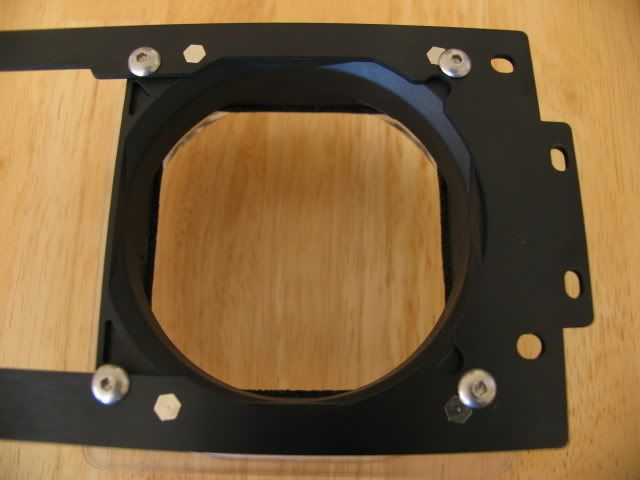
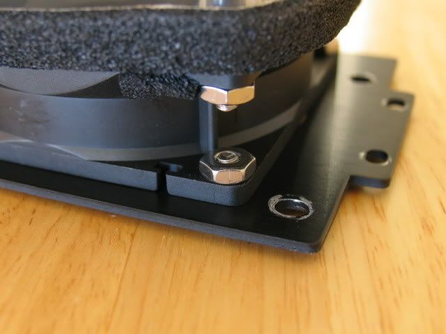
Here is the mounting plate supplied by Lian-Li (with some clearance holes for some 8-32 screws added by yours truly)
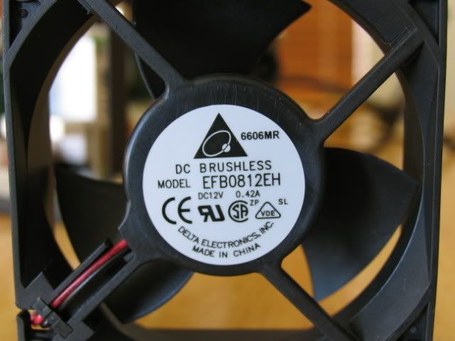
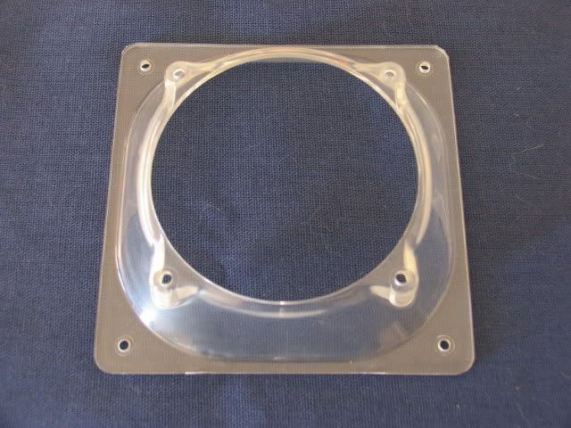
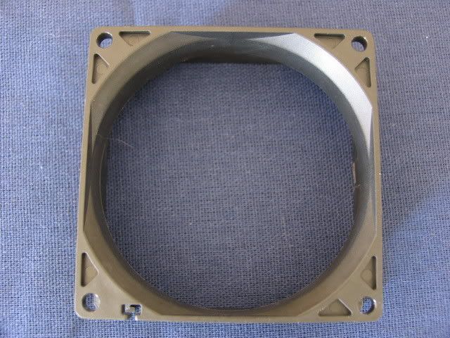
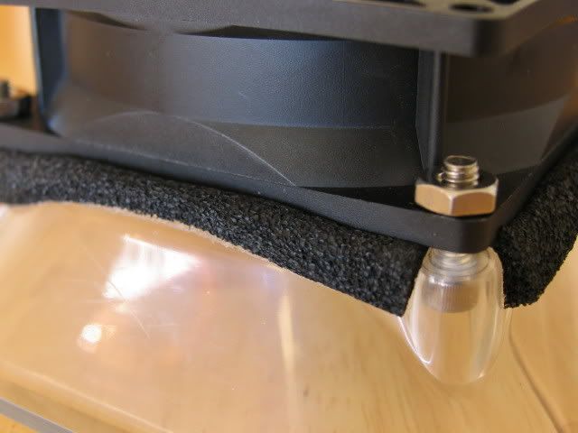
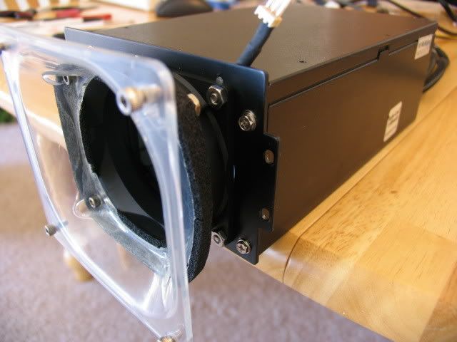
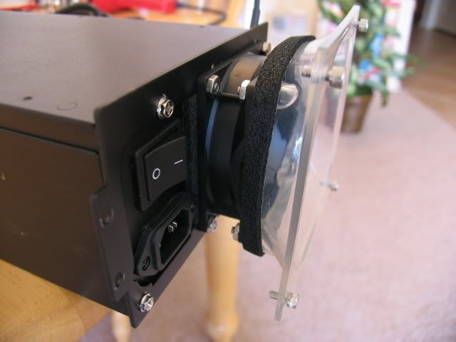
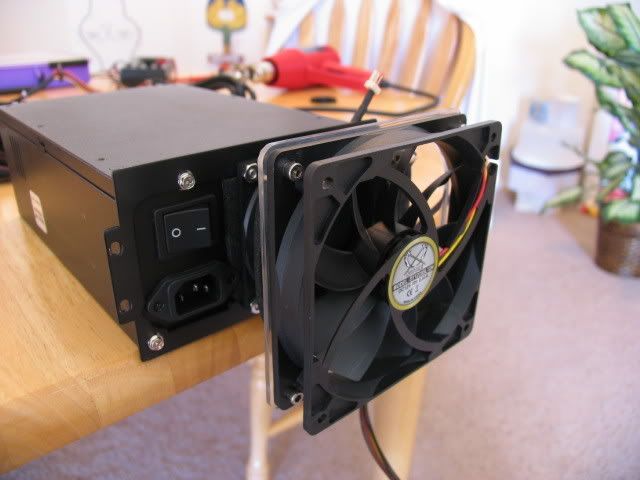
Here is the 80mm to 120mm adapter
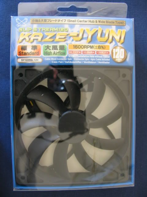
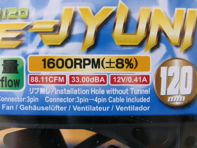
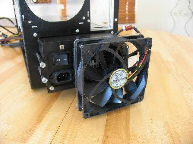
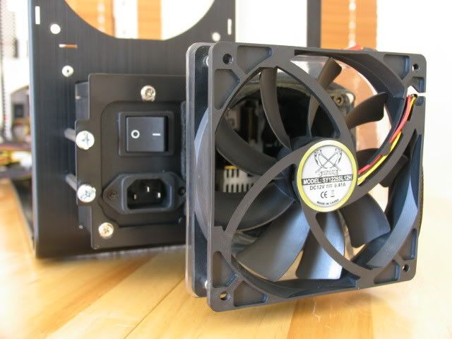
Here is the 120mm fan (almost the same amperage spec but turns slower, is quieter, and moves WAY more air)
Here is a trial fit
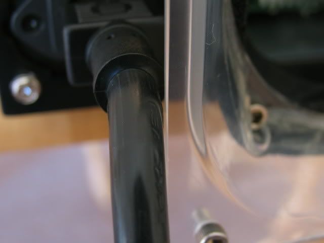
Oh NO!! The plug wont fit!
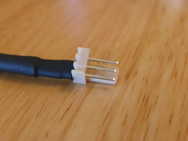
The long plug
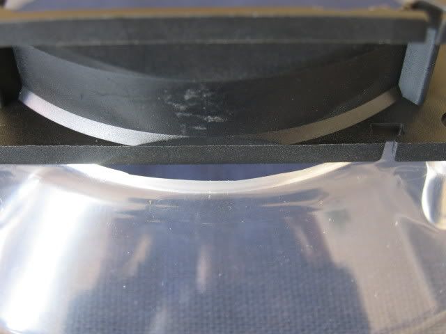
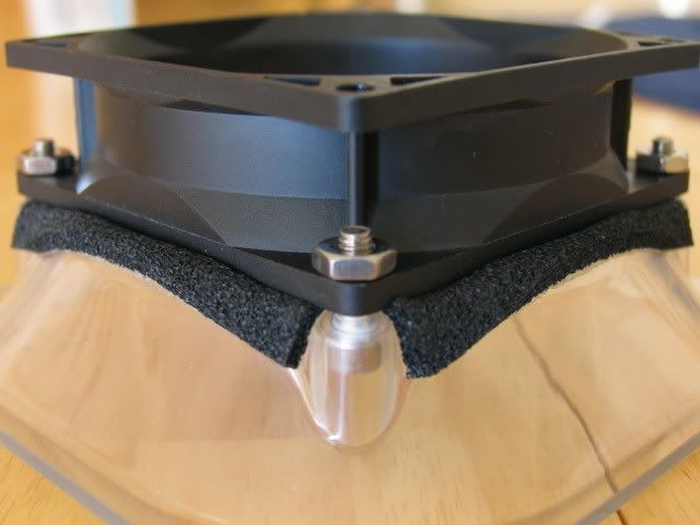
What I need is more room, no prob. Just gut an old fan for a spacer
Here is the spacer and the adapter lined up. Oh no (again). The 80mm hole end of the adapter is way too big
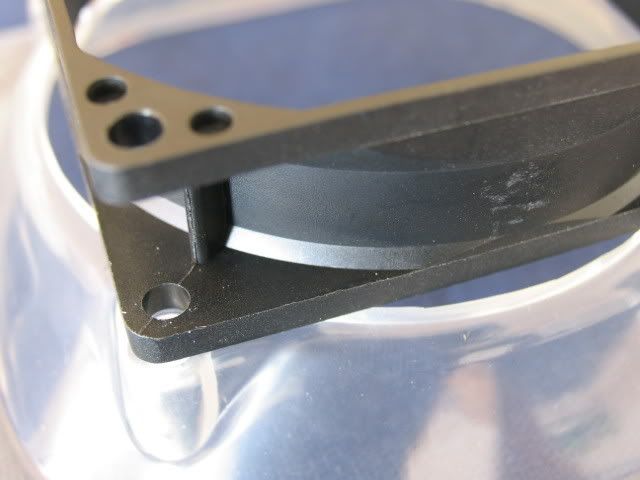
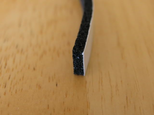
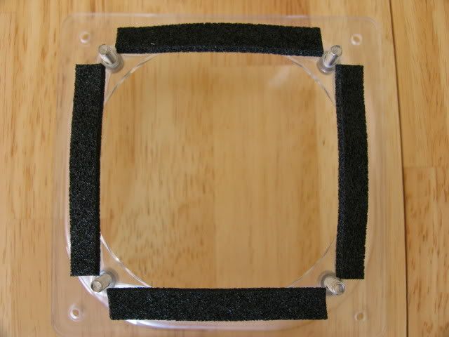
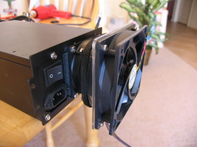
How to fill the space? Weather stripping! Yea!
In place
Other side
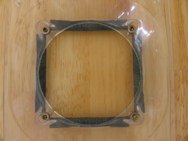
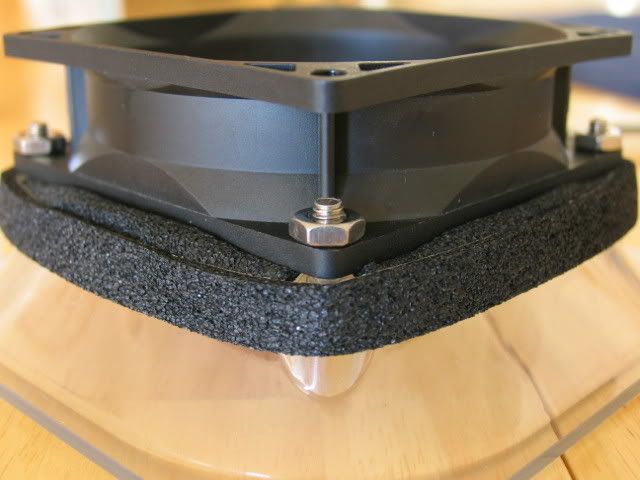
Spacer and adapter joined
The weather stripping started to un-stick, so I added another layer
Time to attach the mounting plate
Time to splice the weird connector to something a little more common
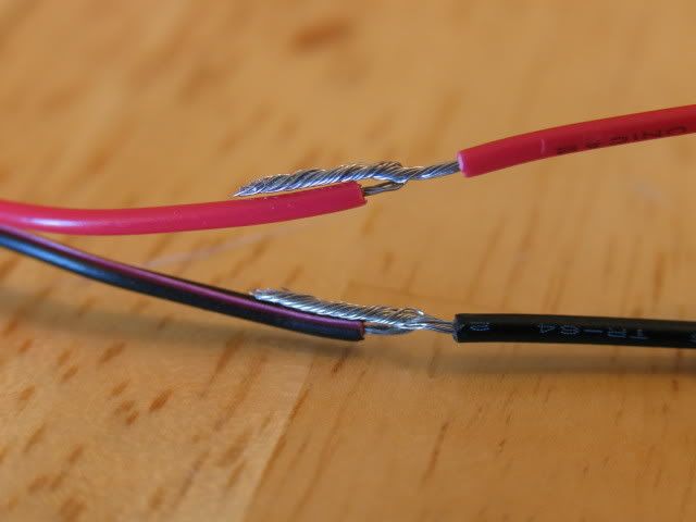
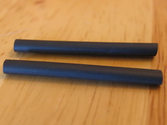
Shrink tube
A little heat
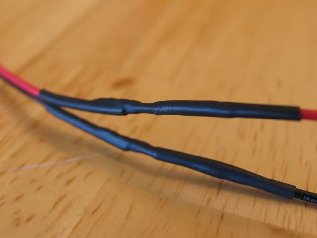
And some sleeving (and more shrink)
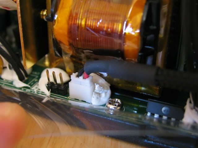
Connected
I added this stripping to fill in this gap
Time to reassemble
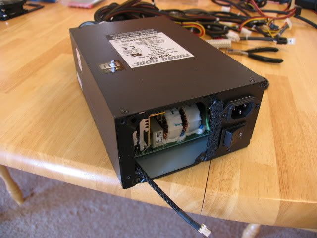
Plate added
I hope the plug fits
Yea!!
Close!
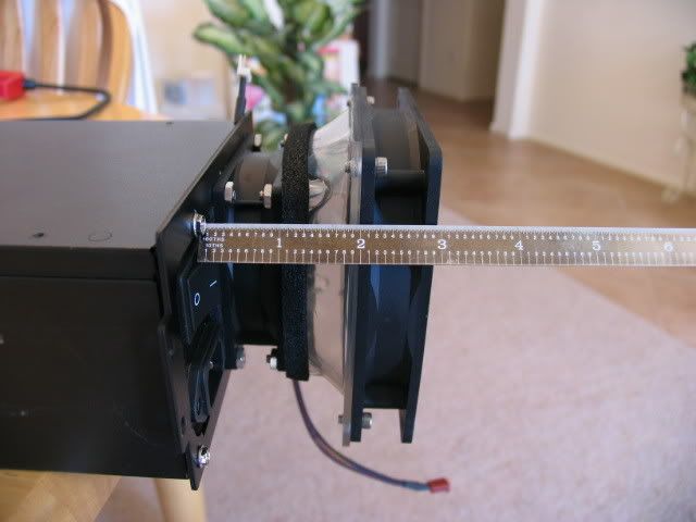
With 120mm fan added
Three more inches sticking out!!
Installed into case
That mother sticks out more than 5 inches past the back of the case. Holy shiznit!
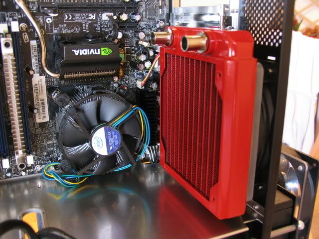
I also knew having the 360 rad inside the case was going to hinder my SLI set-up, so Im moving the rad to the outside of the case. Just need some slots to feed the fan wires.
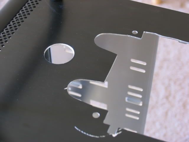
Here are the slots, with more boo boos
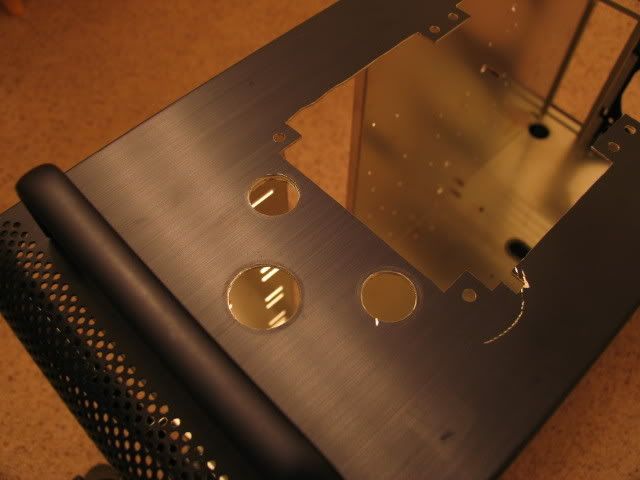
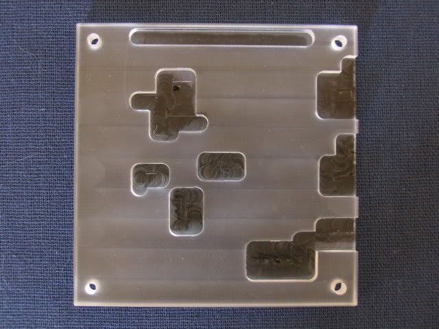
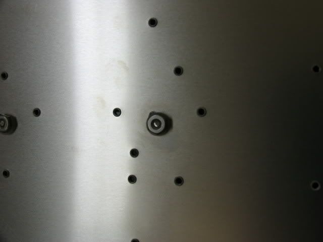
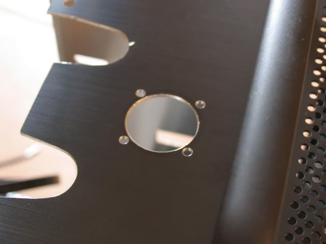
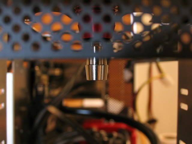
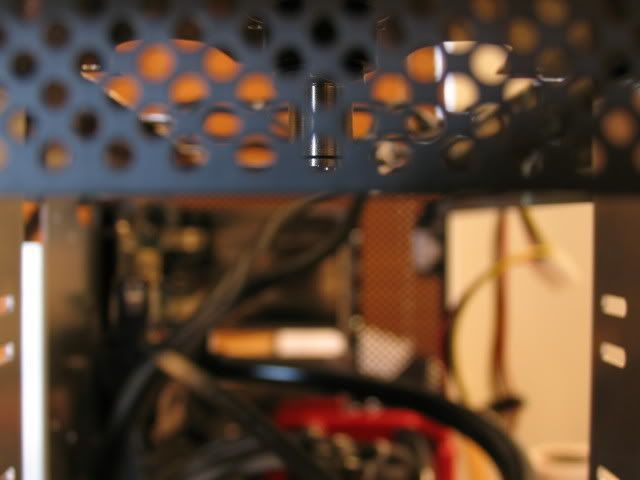
I also needed some way to attach and un-attach the H2O block on the southbridge without having to remove the mobo, so holes
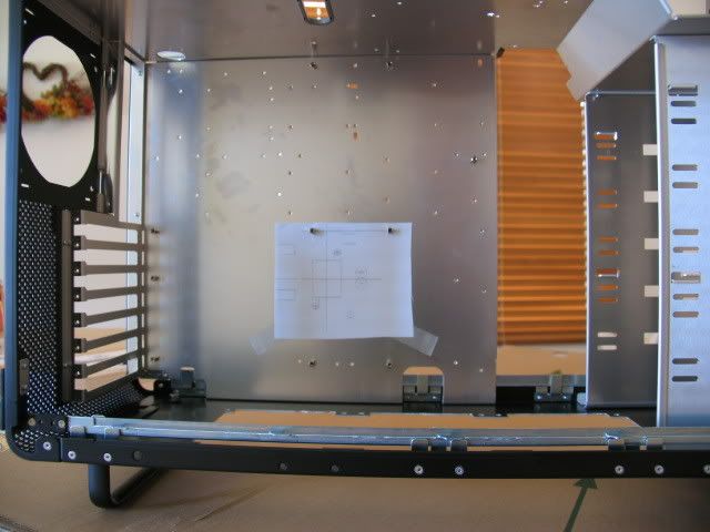
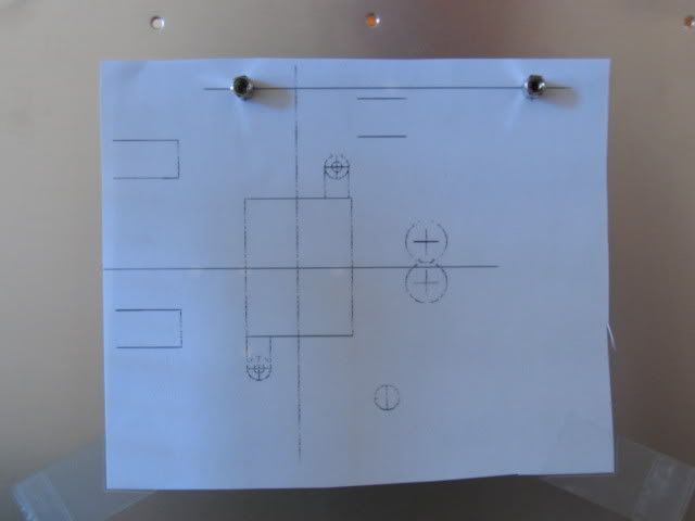
I hope I did my math correctly
Holes
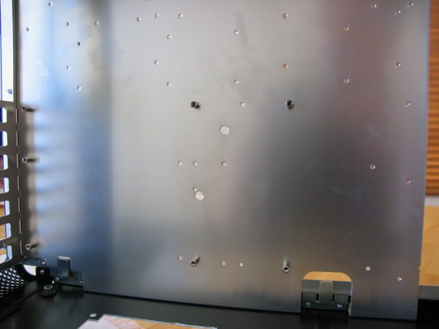
I also added some holes for the 360 rad fittings (seen in previous pic)
I then slotted them so I could remove the rad without having to break the loop
Thats all for now. I see the release date for Crysis is looming. I better get busy.
Chow for now.
Yea, I have been busy. On with the update!
For those of you who own an 8800GTX and DangerDen H2O block to cool it, the insides:
Some of these delrin burrs are totally unacceptable
The sealing gasket is also nothing to write home about (I thought for sure it would be rounded). I can see why some are blowing them out
More
Naked
Close-up
Looks like it was cast and then bead blasted
One more
Here is the wiring of the pumps, needs some Steve magic
Abracadabra
I added this hole for the 8-pin power plug (right where it is on the mobo)
I had read the fan on the PC Power and Cooling 1KW Turbo cool was loud, so I figured that modding it to a 120mm would be a cool idea (so I initially thought).
Here are some shots of the innards, here you can see just how close the fan is
No fan
The loud stock fan
They couldnt use a standard connector (grrrrr)
Home of the bastard connector
Some other misc. shots
Here is the mounting plate supplied by Lian-Li (with some clearance holes for some 8-32 screws added by yours truly)
Here is the 80mm to 120mm adapter
Here is the 120mm fan (almost the same amperage spec but turns slower, is quieter, and moves WAY more air)
Here is a trial fit
Oh NO!! The plug wont fit!
The long plug
What I need is more room, no prob. Just gut an old fan for a spacer
Here is the spacer and the adapter lined up. Oh no (again). The 80mm hole end of the adapter is way too big
How to fill the space? Weather stripping! Yea!
In place
Other side
Spacer and adapter joined
The weather stripping started to un-stick, so I added another layer
Time to attach the mounting plate
Time to splice the weird connector to something a little more common
Shrink tube
A little heat
And some sleeving (and more shrink)
Connected
I added this stripping to fill in this gap
Time to reassemble
Plate added
I hope the plug fits
Yea!!
Close!
With 120mm fan added
Three more inches sticking out!!
Installed into case
That mother sticks out more than 5 inches past the back of the case. Holy shiznit!
I also knew having the 360 rad inside the case was going to hinder my SLI set-up, so Im moving the rad to the outside of the case. Just need some slots to feed the fan wires.
Here are the slots, with more boo boos
I also needed some way to attach and un-attach the H2O block on the southbridge without having to remove the mobo, so holes
I hope I did my math correctly
Holes
I also added some holes for the 360 rad fittings (seen in previous pic)
I then slotted them so I could remove the rad without having to break the loop
Thats all for now. I see the release date for Crysis is looming. I better get busy.
Chow for now.
Mr_And3rsson
Weaksauce
- Joined
- Jun 6, 2006
- Messages
- 93
nice work, however i don't realy like that it sticks out so much at the back looks kinda weird
looks kinda weirdViperlover
Gawd
- Joined
- Jun 7, 2006
- Messages
- 631
Word.nice work, however i don't realy like that it sticks out so much at the back
digital_exhaust
[H]ard|DCer of the Month - May 2008
- Joined
- Aug 14, 2006
- Messages
- 6,903
Keep it up man... it's looking really good so far, and personally, I think the PSU mods are cool... I like the way it sticks out the back....
Concentric
[H]ard|Gawd
- Joined
- Oct 15, 2007
- Messages
- 1,028
The PSU fan mod's a good idea but it needs to look more... sleek. Maybe if the 80-120 converter were black too?
Stevennoland
Limp Gawd
- Joined
- Jan 5, 2006
- Messages
- 418
The PSU fan mod's a good idea but it needs to look more... sleek. Maybe if the 80-120 converter were black too?
Thanks. If you can find me a black one I'll buy it! I tried looking all over the net, but no luck. Yea, I hate that it sticks out so far. Without the fan mod it only stuck out about 2 inches. The mod made it worse!
I sure hope it cools just as well, but at half the noise.
Stevennoland
Limp Gawd
- Joined
- Jan 5, 2006
- Messages
- 418
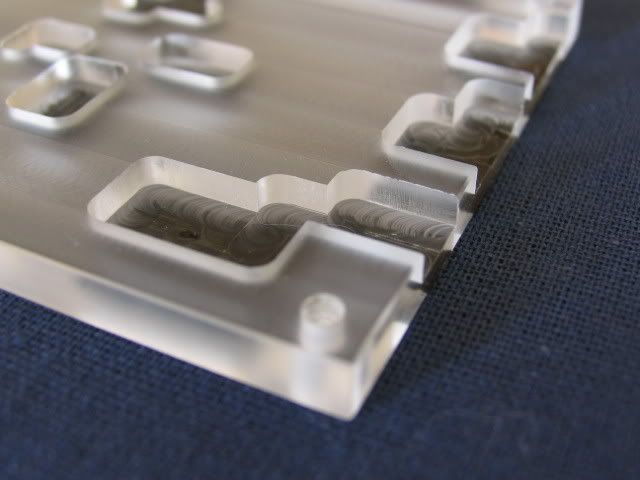
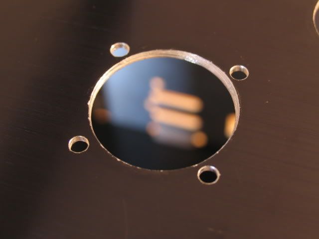
damn, I wish I had access to a CNC. Quick question about that southbridge block though... with the angled access holes that you have, won't the water just flow down one and right back up the other? That looks like a lot of dead space for the water to just sit around heating up and not moving.
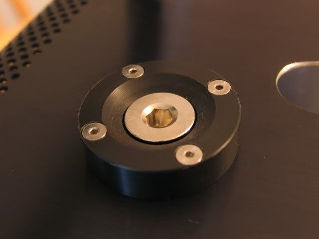
In one of the pictures there is a shot of the holes on the sealing side of the plexi. You can see the opening is elliptical in shape. The coolant will actually fill the space quite well. The flow will also be enough to keep things from becoming stagnant.
Concentric
[H]ard|Gawd
- Joined
- Oct 15, 2007
- Messages
- 1,028
Thanks. If you can find me a black one I'll buy it! I tried looking all over the net, but no luck. Yea, I hate that it sticks out so far. Without the fan mod it only stuck out about 2 inches. The mod made it worse!
I sure hope it cools just as well, but at half the noise.
Ah ok. What about spray painting it?
Looks awesome though, keep the updates coming.
filthysanchez
2[H]4U
- Joined
- Jul 19, 2006
- Messages
- 2,669
Since you already voided the warranty, why don't you trim the case of the PSU to fit, and use a nice 92 mm scythe/panaflo fan that you can just drill holes for on the back, and not have to bother using an adapter?
Acidzerocool
Gawd
- Joined
- Feb 1, 2005
- Messages
- 531
Bump for jsut reading the entire thread and need updates.....
Concentric
[H]ard|Gawd
- Joined
- Oct 15, 2007
- Messages
- 1,028
And what happened to this one? Any updates Steveno?
Stevennoland
Limp Gawd
- Joined
- Jan 5, 2006
- Messages
- 418
Short of death, I will have an update tomorrow 28 Dec 2007. Sorry, but life intrudes, and work, and school, and my new tv (plus hi-def players), and the wife! Nuff said.
Stevennoland
Limp Gawd
- Joined
- Jan 5, 2006
- Messages
- 418
Yea, I know, I promised an update yesterday. Sorry.
I was busy trying to fill this damn thing. What a royal PITA!
This set-up doesnt allow for easy air-bleeding. The res is in a tight space.
Im gonna figure out a new strategy today.
But lets get up to speed.
I wanted to try out all the components before I went with the liquid cooling, so ..
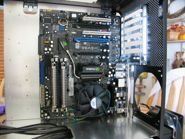
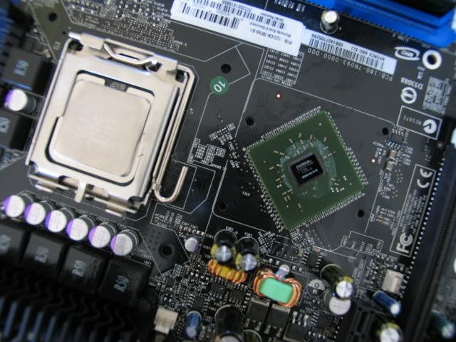
Here is the mobo installed with the clunky Intel fan assembly
Hole and 8-pin power plug
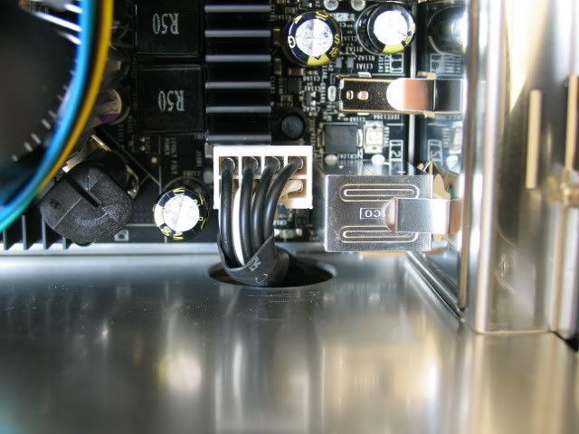
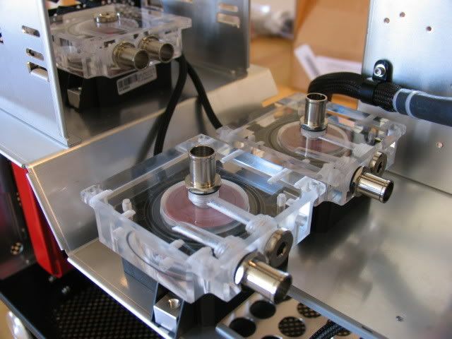
Home of the three pumps
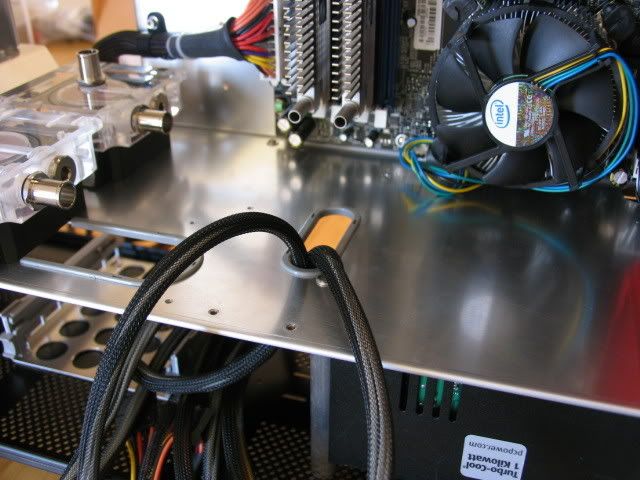
This is the slot I needed for the GPU power lines (the reason the PSU sticks out)
Yea, I could have routed the GPU power lines somewhere else, but Im getting lazy in my old age
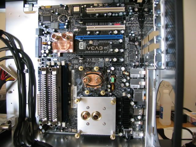
Just enough room for the CPU block
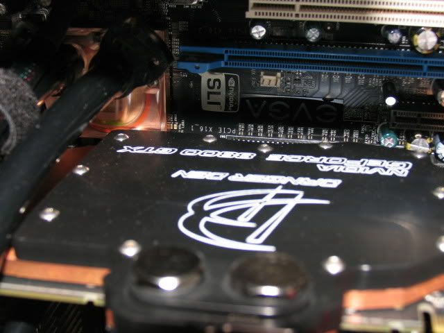
8800 GTX installed
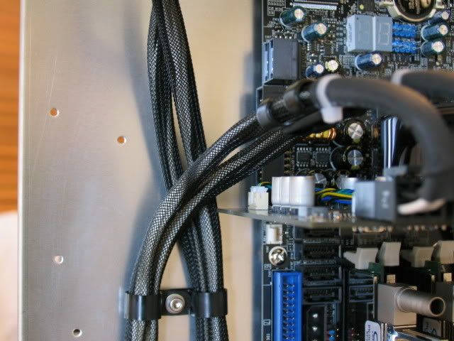
GPU power line routing
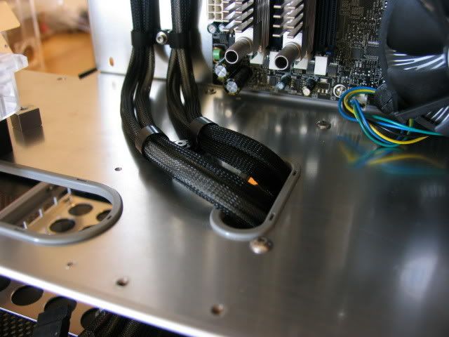
Tie-downs
Connected
Im going SLI some day, so the extra lines
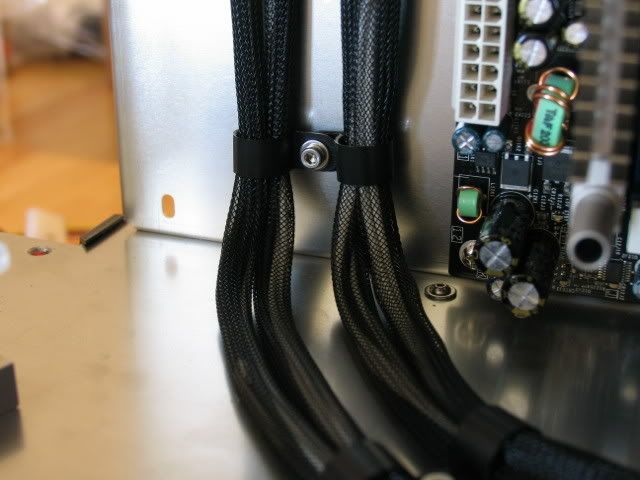
24 pin mobo
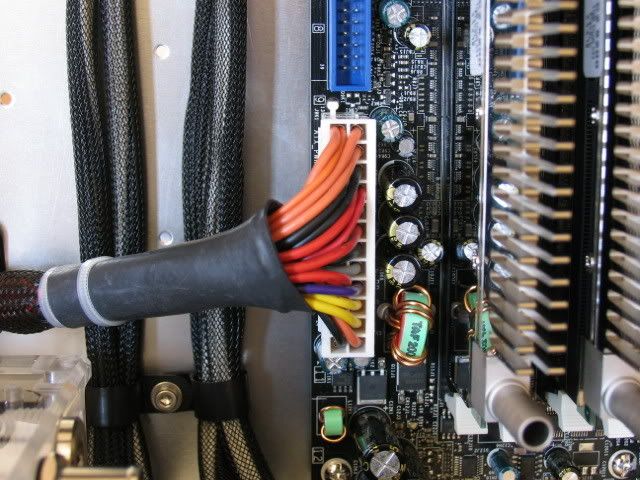
Securing
Routing
Underside
Close-ups
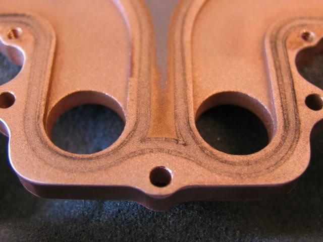
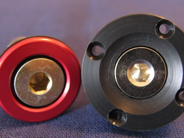
Here are the cpu, north and south bridge blocks
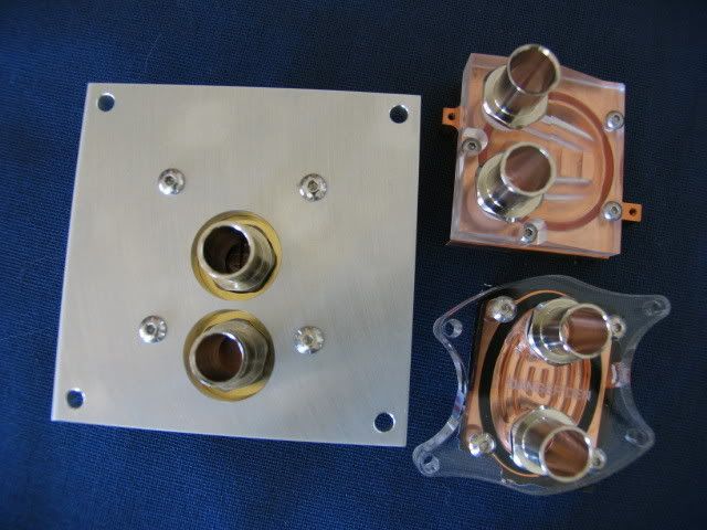
Northbridge chip
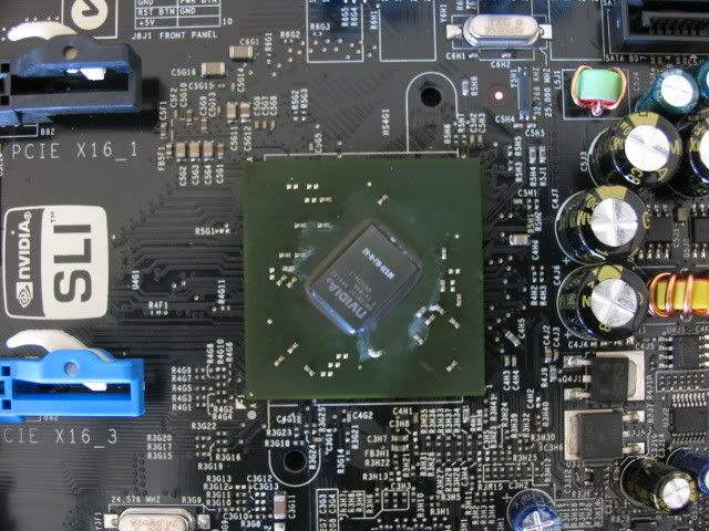
Southbridge chip
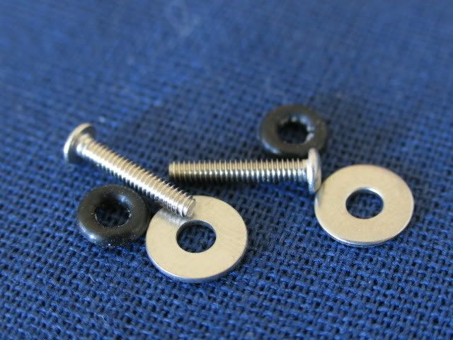
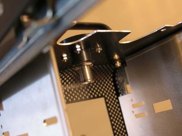
Screws for securing the southbridge block
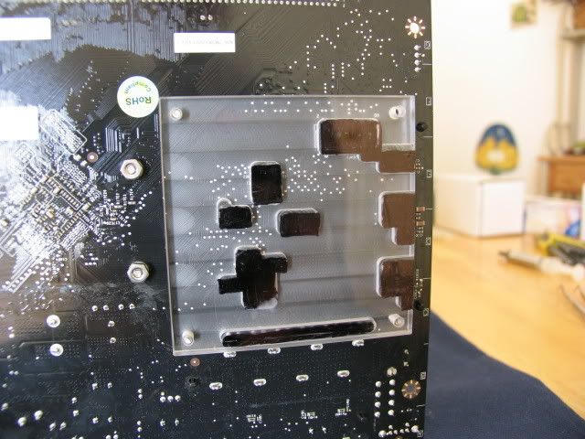
This is the CPU back support plate. I have never been a fan of securing the CPU block to just the mobo. I prefer to have the posts go through the mobo and secure them to the case. This plate prevents the mobo from bowing as the CPU block is secured. (Its like a sandwich, case-support block-mobo-CPU-CPU cooling block, get it?)
Close-up
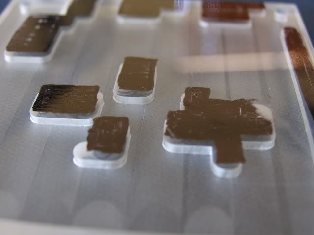
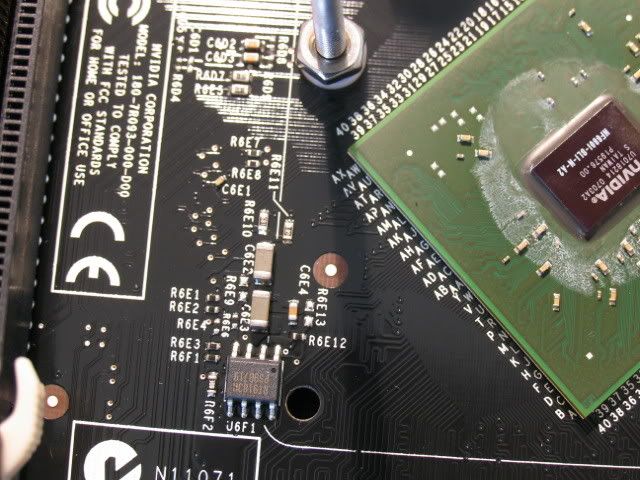
I want the support plate to sit flush with the back of the mobo. But mobo makers dont want to play nice, so they solder these little protruding whatevers to the back side. I then have to machine clearance gaps to achieve a flush fit. The marker was used to identify the rough location of the items to be cleared.
Another mobo flub. This chip was placed to close to the Northbridge mounting hole so I couldnt properly install the mounting post
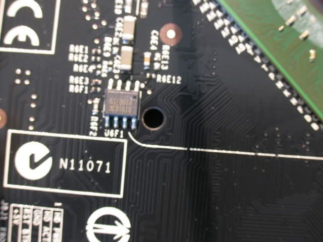
See
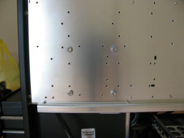
Back plate installed (the posts will protrude past this after the mobo is installed)
Here are the screws holding the posts for the CPU block
Close-up (blurry, I know)
Blocks installed!
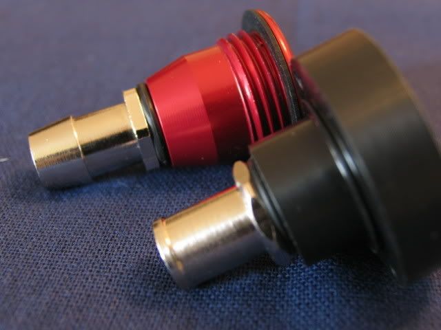
This is the fill port that Danger Den sells
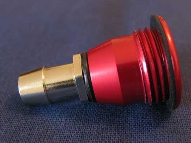
Its a little too long so I made my own
Its a little bigger round wise, but thats ok
Here you can see the length difference
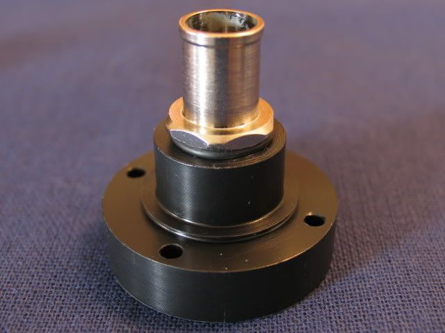
Here is the original port hole with mounting screw holes added
Close-up
Here is the original fill port installed
And mine
Secured
underside view
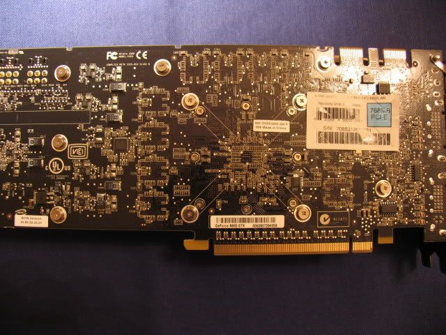
Here is the GPU block process (albeit a quick one), back side view
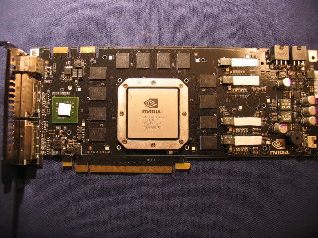
Front, with some thermal pads installed
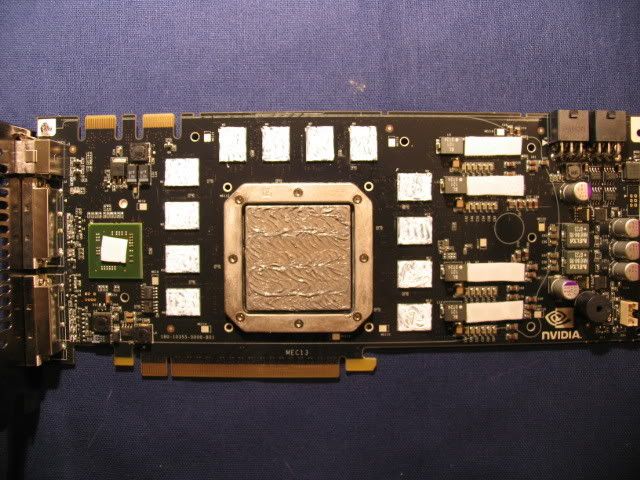
Memory pads installed and some AS on the GPU
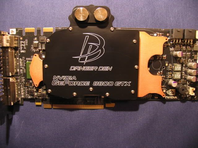
And block!
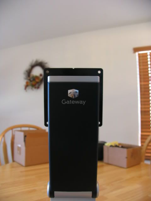
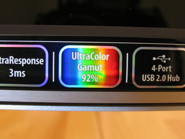
My Dell 24 lcd was fantastic for its day, but I wanted to upgrade, so I splurged and got this
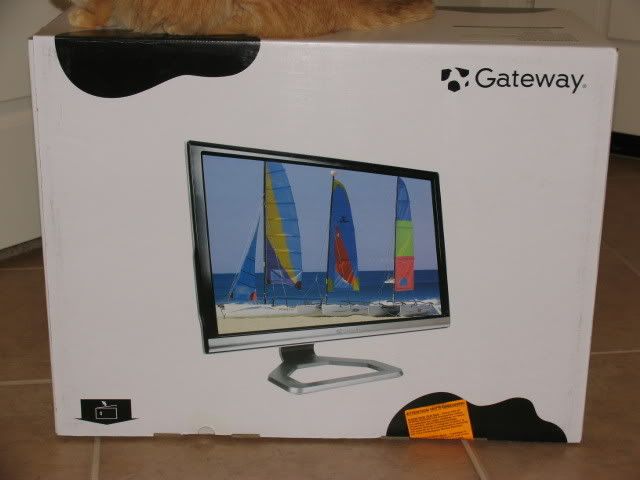
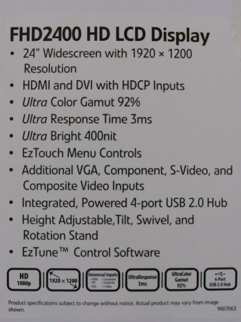
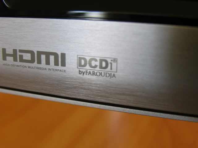
Check those specs!
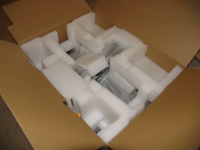
Unpacking
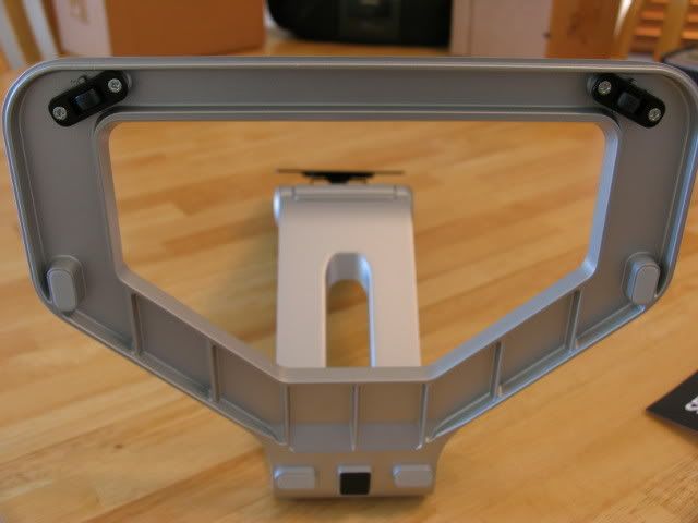
Stand
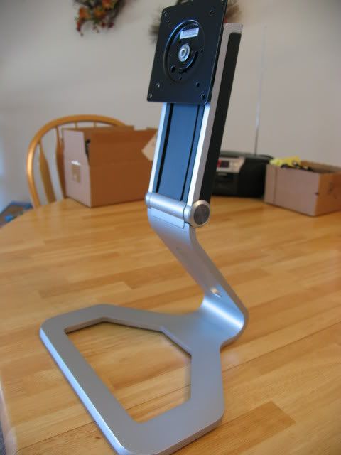
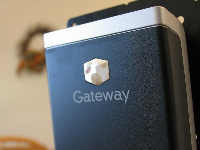
This stand is really nice. Excellent craftsmanship.
Close-ups

The bottom is designed so you can swivel
Attached
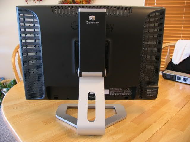
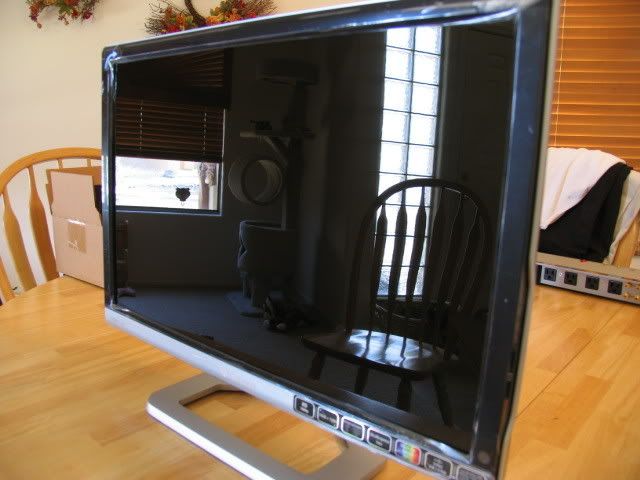
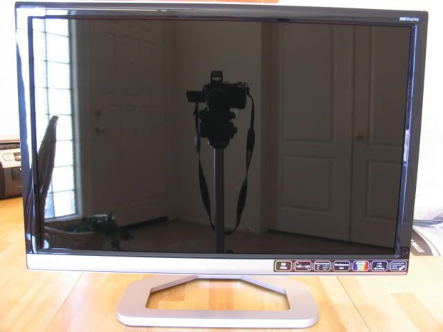
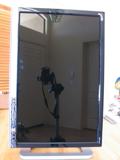
Unwrapped
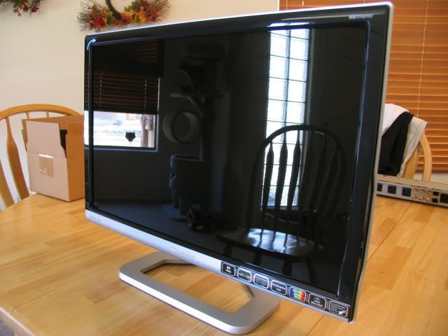
Im hoping that glare wont be too much of a problem (that is reflective)
Internal scaler (nice)
More colors!
Portrait mode (which Ill never use)
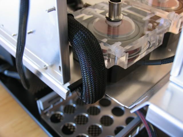
Now its time for the liquid cooling installation. I didnt do as detailed an installation as I would have like, but most of you will get the jist.
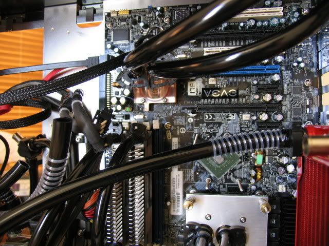
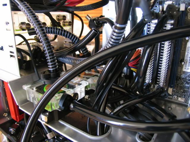
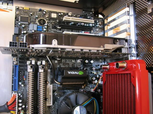
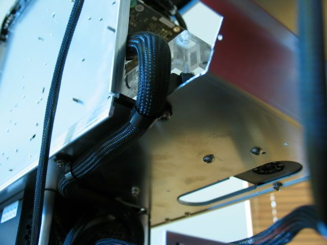
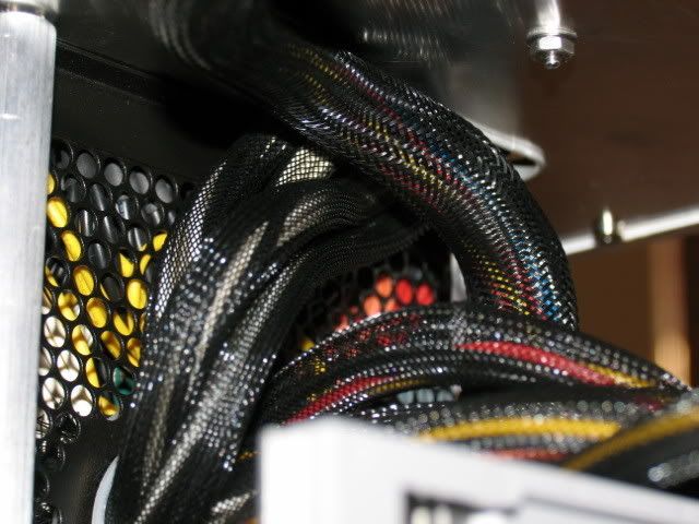
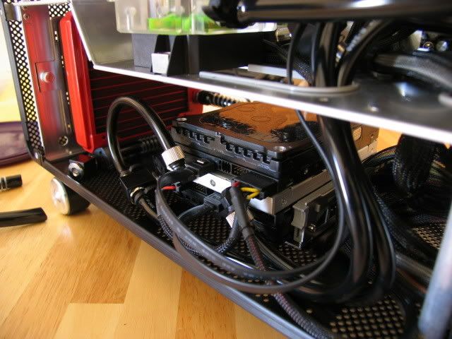
HDD routing
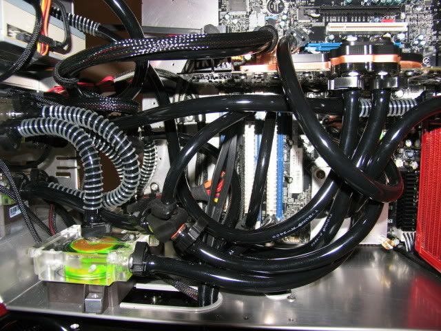
It may look cluttered (and it is), but if anyone can cram all this in and make it look neater, be my guest (Oh no! The can-o-worms of comments flood in)
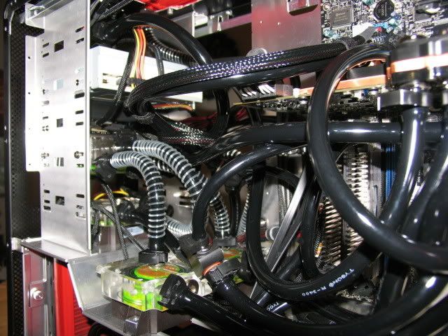
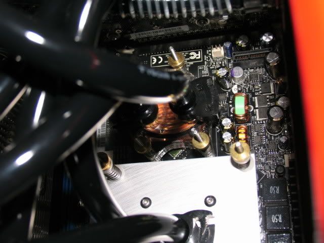
Close-ups
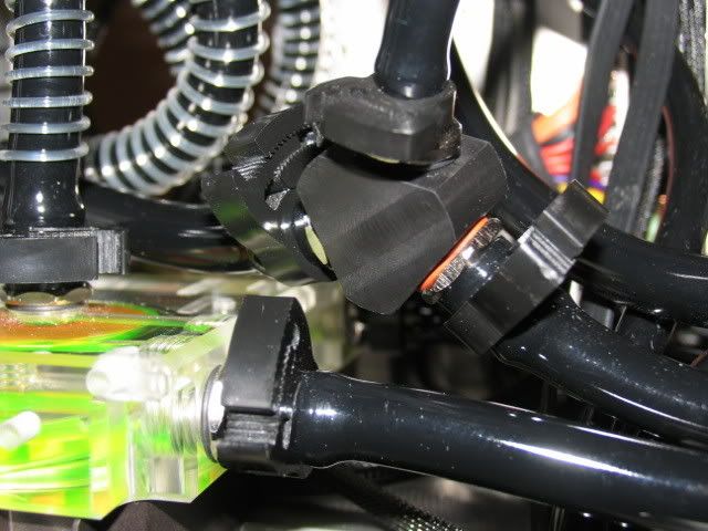
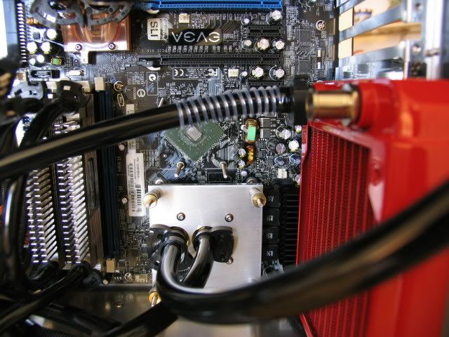
Southbridge
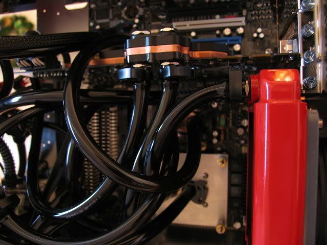
GPU
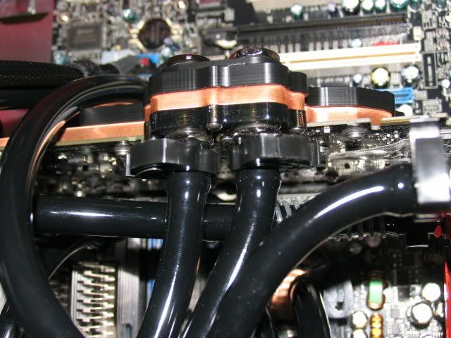
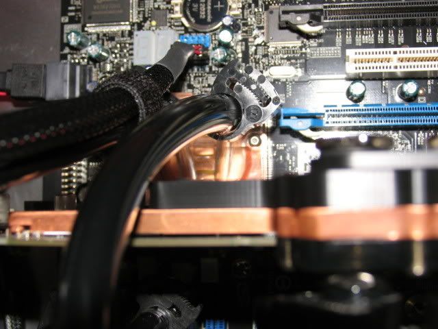
Northbridge
Drain tee
HDD again, close-up
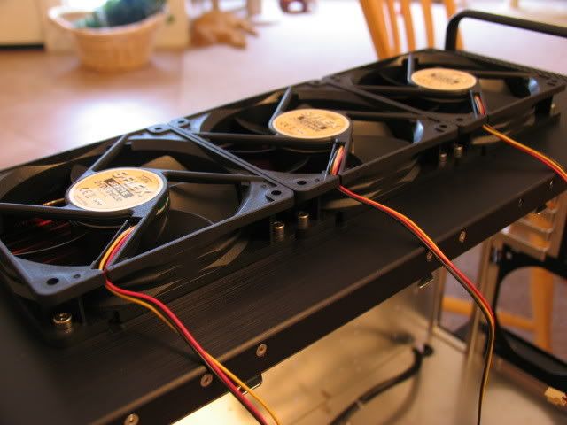
Underside shot of the 360 radiator
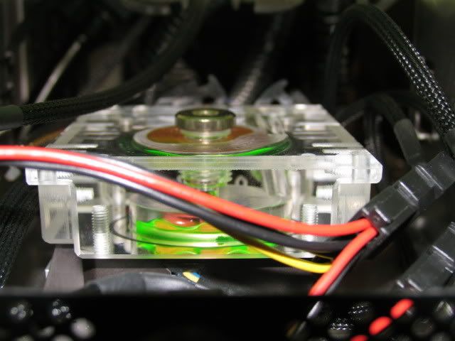
Front pump
Top of the GPU
Thats it so far. Ill post some screen shots when I get this thing bled and up and running.
Thanks for your patience.
I was busy trying to fill this damn thing. What a royal PITA!
This set-up doesnt allow for easy air-bleeding. The res is in a tight space.
Im gonna figure out a new strategy today.
But lets get up to speed.
I wanted to try out all the components before I went with the liquid cooling, so ..
Here is the mobo installed with the clunky Intel fan assembly
Hole and 8-pin power plug
Home of the three pumps
This is the slot I needed for the GPU power lines (the reason the PSU sticks out)
Yea, I could have routed the GPU power lines somewhere else, but Im getting lazy in my old age
Just enough room for the CPU block
8800 GTX installed
GPU power line routing
Tie-downs
Connected
Im going SLI some day, so the extra lines
24 pin mobo
Securing
Routing
Underside
Close-ups
Here are the cpu, north and south bridge blocks
Northbridge chip
Southbridge chip
Screws for securing the southbridge block
This is the CPU back support plate. I have never been a fan of securing the CPU block to just the mobo. I prefer to have the posts go through the mobo and secure them to the case. This plate prevents the mobo from bowing as the CPU block is secured. (Its like a sandwich, case-support block-mobo-CPU-CPU cooling block, get it?)
Close-up
I want the support plate to sit flush with the back of the mobo. But mobo makers dont want to play nice, so they solder these little protruding whatevers to the back side. I then have to machine clearance gaps to achieve a flush fit. The marker was used to identify the rough location of the items to be cleared.
Another mobo flub. This chip was placed to close to the Northbridge mounting hole so I couldnt properly install the mounting post
See
Back plate installed (the posts will protrude past this after the mobo is installed)
Here are the screws holding the posts for the CPU block
Close-up (blurry, I know)
Blocks installed!
This is the fill port that Danger Den sells
Its a little too long so I made my own
Its a little bigger round wise, but thats ok
Here you can see the length difference
Here is the original port hole with mounting screw holes added
Close-up
Here is the original fill port installed
And mine
Secured
underside view
Here is the GPU block process (albeit a quick one), back side view
Front, with some thermal pads installed
Memory pads installed and some AS on the GPU
And block!
My Dell 24 lcd was fantastic for its day, but I wanted to upgrade, so I splurged and got this
Check those specs!
Unpacking
Stand
This stand is really nice. Excellent craftsmanship.
Close-ups
The bottom is designed so you can swivel
Attached
Unwrapped
Im hoping that glare wont be too much of a problem (that is reflective)
Internal scaler (nice)
More colors!
Portrait mode (which Ill never use)
Now its time for the liquid cooling installation. I didnt do as detailed an installation as I would have like, but most of you will get the jist.
HDD routing
It may look cluttered (and it is), but if anyone can cram all this in and make it look neater, be my guest (Oh no! The can-o-worms of comments flood in)
Close-ups
Southbridge
GPU
Northbridge
Drain tee
HDD again, close-up
Underside shot of the 360 radiator
Front pump
Top of the GPU
Thats it so far. Ill post some screen shots when I get this thing bled and up and running.
Thanks for your patience.
digital_exhaust
[H]ard|DCer of the Month - May 2008
- Joined
- Aug 14, 2006
- Messages
- 6,903
Nice... thanks for the update, we've been waiting ya know
It does look a little cramped, but you certainly did a good job of cramming everything in such a small space. Keep up the good work, and I'll be waiting for more!
It does look a little cramped, but you certainly did a good job of cramming everything in such a small space. Keep up the good work, and I'll be waiting for more!
+4..after going through the pita of adding more wc to my case it made me not give a shit about my pc any more as i did earlyer and im kinda done investing money into it, i was hoping id make it silent but i guess i made it louder by adding wc. damn i suck lol.
Stevennoland
Limp Gawd
- Joined
- Jan 5, 2006
- Messages
- 418
Thanks for the kudos.
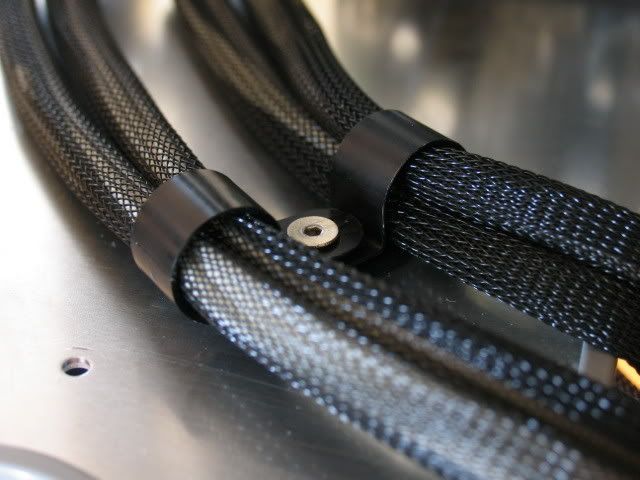
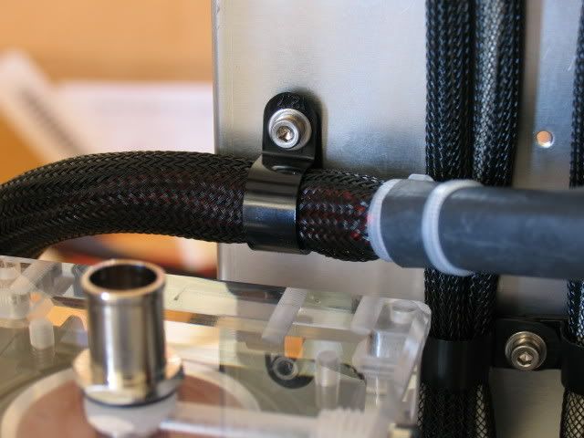
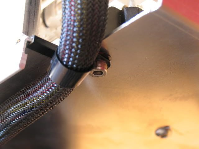
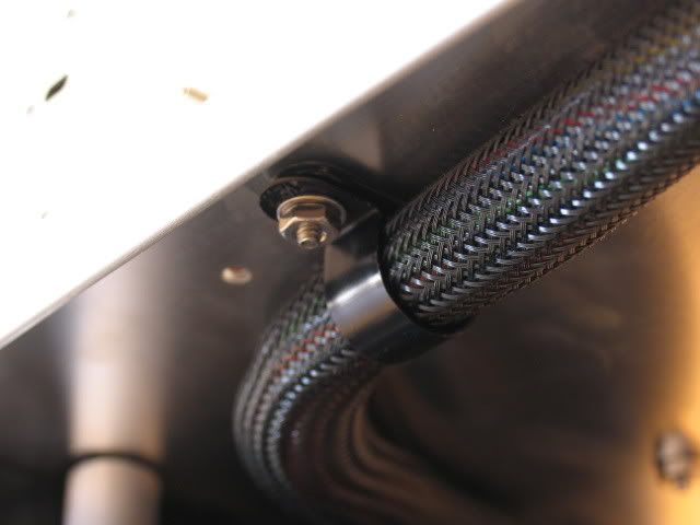
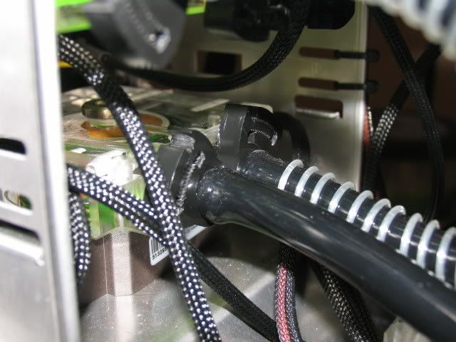
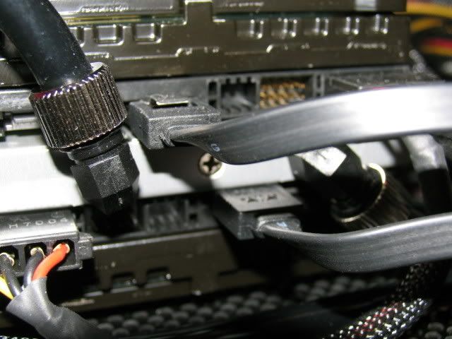
As for the cable clamps:
Goto:
http://www.mcmaster.com/
and in the search box type this:
8876T41
this will bring up the 1/2 dia piece. Other sizes will be listed as well.
The bolt is an M3 metric. Same as all the holes pre-tapped on Lian-Li mobo trays.
Thanks for asking.
As you can see, most sizes come in quantities of 100. I ordered a bag each of size: 1/4, 5/16, 3/8, 7/16, and 1/2 in Nylon.
I didn't use any of the 5/16 or 3/8, and only a couple from the 1/4, 7/16, and 1/2 .
If anyone is interested in obtaining a small quantity, please PM me and I'll see what we can work out.
Stevennoland
Limp Gawd
- Joined
- Jan 5, 2006
- Messages
- 418
congrats
what kind of temps u gettin?
got any pictures of the whole case ?
Temps? I never bothered to check when I had it on air-cool when I was doing the component testing/ OS install.
Other than having a bitch of a time getting the BIOS to see both raptors so I could set-up my RAID 0, everything went fine.
I'll post some pics as soon as I get her air bubble bled (lets call that one ABB).