Newbie Hard Line Tubing Question

Joined
Oct 6, 2023
Messages
5
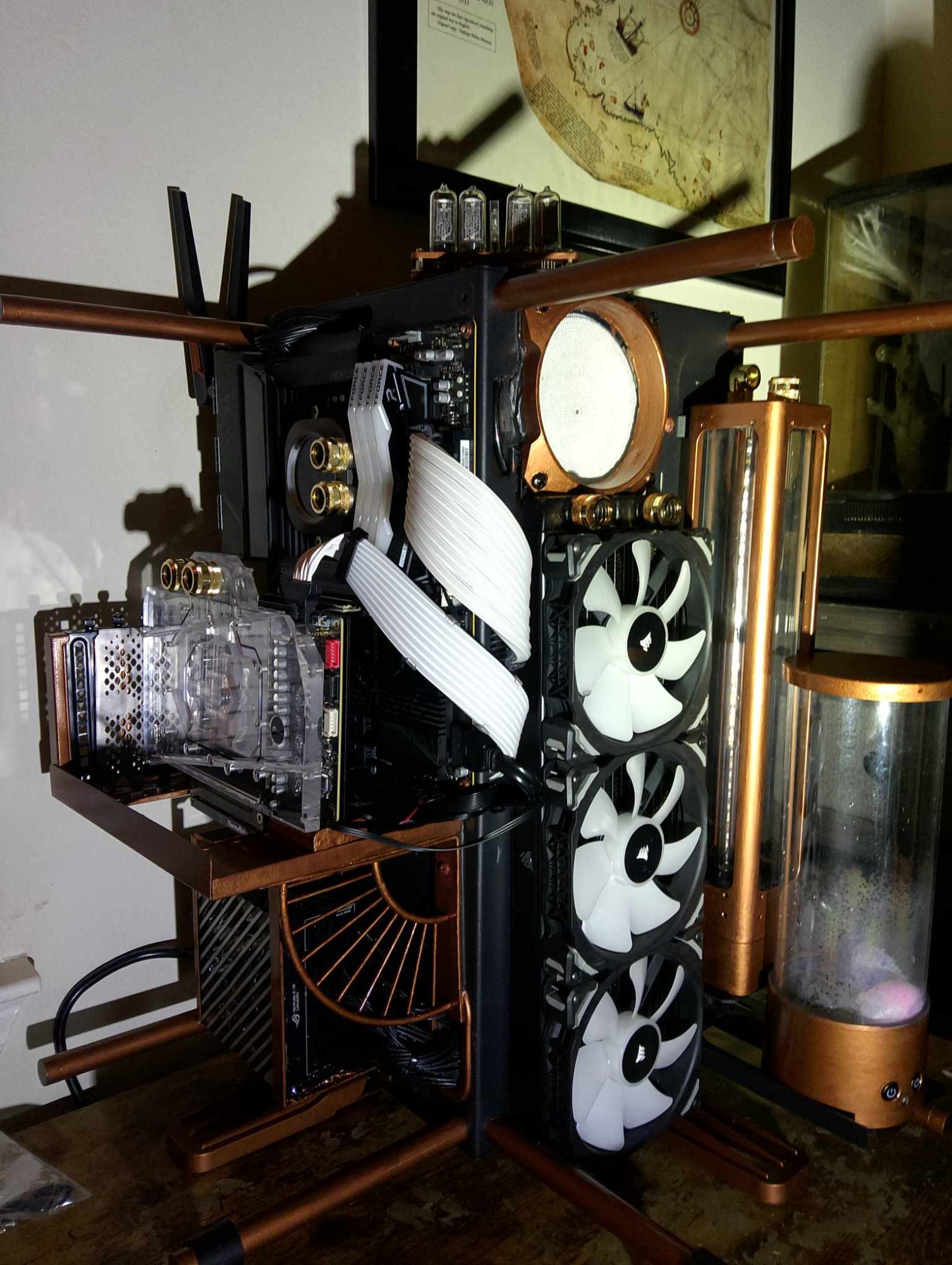
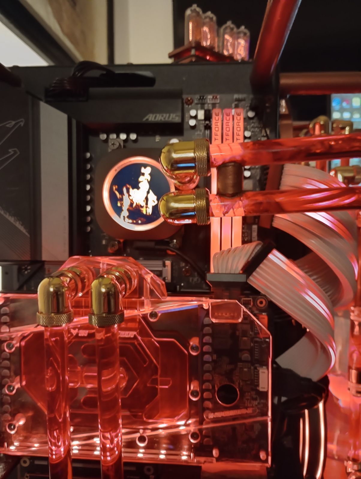
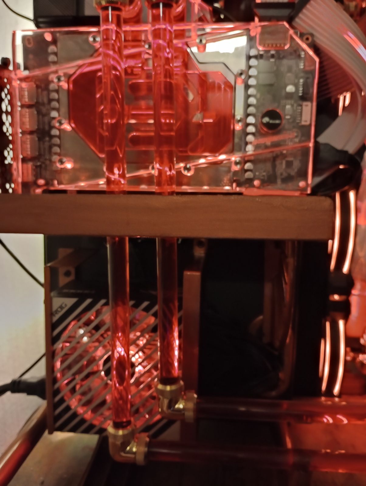
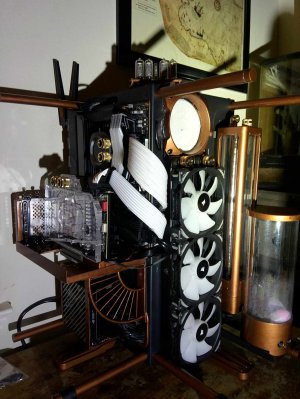
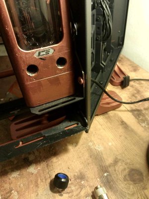
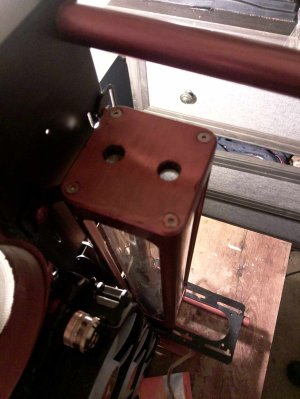
I recently attempted my first PC build and am currently trying to figure out the hard line tubing. I know this will come across as a dumb question but here goes….i was hoping to run the line for the GPU and CPU separately. I believe I can do this with the pump (Alphacool Apex Pump) and reservoir (ICE-DX5) I have but am not sure. The reason I believe I can run them separately is because instead of one hole on both the top and bottom of the reservoir there are two. I know that normally the flow goes from the pump to the GPU then from the GPU to the CPU then from the CPU to the radiator then back into the reservoir. The problem is that even though there are two holes in both the top and bottom of the reservoir instead of the normal one on each, the radiator still has only one inlet and one outlet. I understand I could be completely off but am I in fact correct that the two holes on both the top and bottom of the reservoir mean I can run the tubing to the GPU and CPU separately? One hole on the bottom as an inlet for the GPU and the other hole as a separate inlet for the CPU? I was thinking of combining both the CPU and GPU returns into the same tube to then flow into the one radiator inlet then using one of the holes on top of the reservoir as the radiator outlet. I’m guessing normally when the GPU and CPU are running separately the second hole on top of the reservoir is for a second radiator? How horribly off and misguided am I with any of this? J

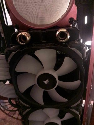
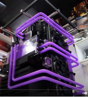
Pics below are of the two holes on both the top and bottom of the reservoir and also of the build itself also a pic of the hardline tubing I’m sort of going for.
 

Attachments

  • 411632679_1101731174317116_1836084035927897274_n.jpg
    411632679_1101731174317116_1836084035927897274_n.jpg
    434.9 KB · Views: 0
  • 409770351_1114714286393365_7813693319085435144_n.jpg
    409770351_1114714286393365_7813693319085435144_n.jpg
    407 KB · Views: 0
  • 411998720_1803408230106776_7406638108435535216_n.jpg
    411998720_1803408230106776_7406638108435535216_n.jpg
    334.2 KB · Views: 0
  • 411618869_271397665920711_3772793932337349378_n.jpg
    411618869_271397665920711_3772793932337349378_n.jpg
    350.4 KB · Views: 0
  • 3.JPG
    3.JPG
    72.6 KB · Views: 0
1703398566283.png

one in, one out, so no it does not work that way. regardless, one the water equalizes it doesnt matter how you run the tubes.
 
View attachment 622261
one in, one out, so no it does not work that way. regardless, one the water equalizes it doesnt matter how you run the tubes.
"doesnt matter how you run the tubes"...thats what i thought also.The advise i got was a bit complacated....
Found the manual on Amazon of all places. While the diagram only showing 2 inputs and 1 out, I don't see why you can't use both inputs at the same time. You can't use the top hole for outlet, never designed that way so you have to use the hole with the downward arrow as the output. The pump is at the bottom and it sucks the water out of the bottom and then out of the hole. You could either use a 3 way valve to split the output from the radiator to both CPU and GPU blocks. Not sure if you also need a check valve to make sure one of the block doesn't push water back the other way.
  1. Rad output to 3 way valve
  2. 3 way valve to CPU and GPU block input (add a check valve to one of the 2 output just in case
  3. CPU to top of ICE-DX5
  4. GPU to bottom of ICE-DX5
  5. ICE-DX5 bottom out to rad
I figured if i only had one outlet and two inlets i would just use a couple of 3-way valves...one to spit the reservoir outlet and one to split the radiator inlet.
I tried to figure out how the two individual lines flowed in the video I was trying to replicate and even took some screen shots of how it was set up in the back of the case but there’s too much that’s not shown. The tubing install starts at 14:35

View: https://www.youtube.com/watch?v=glpZ0nEe78Y
 
Ok, first Declassified Systems is the benchmark IMO, good guy to try and emulate. What he is doing is hiding his tubing path around the back so it appears as if the cpu and gpu have two seperate feeds. He could have a distro back there, but likely just uturns in the loop. If you watch when it is getting filled the fluid still goes gpu to cpu before ever getting back to the reservoir. He goes into detail about loop construction in this video
View: https://www.youtube.com/watch?v=BTk-ARD9aec around the 6 minute mark. Not exactly the same but you can see how he hides the true path of the liquid. NINJA EDIT: He shows what he is doing around minute 11 of your video. He is using pass through fittings and 90 degree turns behind the rad to the flow meters, giving the illusion of two flow paths. It is just one really long snaking path, one pump, one res, one in , one out.
 
Last edited:
By the way, I like the copper effect you have on the res. Is that just spray paint? Looks cool, has a "corrosion" effect to my eyes.
 
By the way, I like the copper effect you have on the res. Is that just spray paint? Looks cool, has a "corrosion" effect to my eyes.
Yeah it was just some copper paint. I decided to run just one line but instead of running directly from the GPU to the CPU I went around the long way to appear as two separate lines.
IMG_20240125_225929~2.jpg

By the way, I like the copper effect you have on the res. Is that just spray paint? Looks cool, has a "corrosion" effect to my eyes.
No just regular copper model paint
 

Attachments

  • IMG_20240125_231931.jpg
    IMG_20240125_231931.jpg
    141.8 KB · Views: 0
  • IMG_20240125_231936~2.jpg
    IMG_20240125_231936~2.jpg
    249.9 KB · Views: 0
  • IMG_20240125_225926.jpg
    IMG_20240125_225926.jpg
    201.8 KB · Views: 0
  • IMG_20240125_225934.jpg
    IMG_20240125_225934.jpg
    171.9 KB · Views: 0
Back
Top