sortableturnip
Limp Gawd
- Joined
- Aug 12, 2011
- Messages
- 213
Looking good so far ")
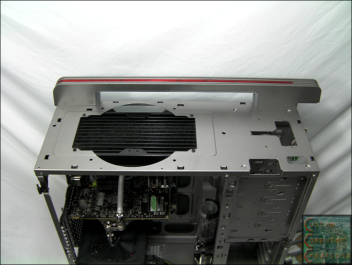
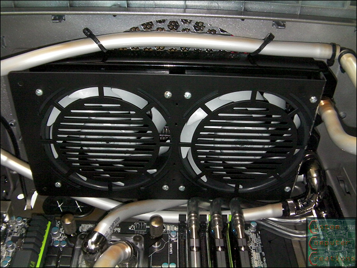
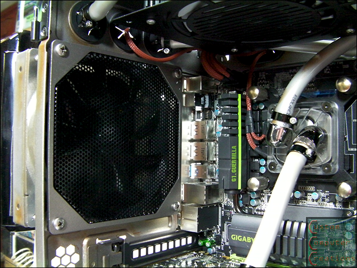
Just an observation, I read here that the static pressure of those Cooler Master fans is not good for use with heatsinks/rads. Basically, it doesn't have the pressure necessary to force the air through the obstacle behind it.
Just an observation, I read here that the static pressure of those Cooler Master fans is not good for use with heatsinks/rads. Basically, it doesn't have the pressure necessary to force the air through the obstacle behind it.