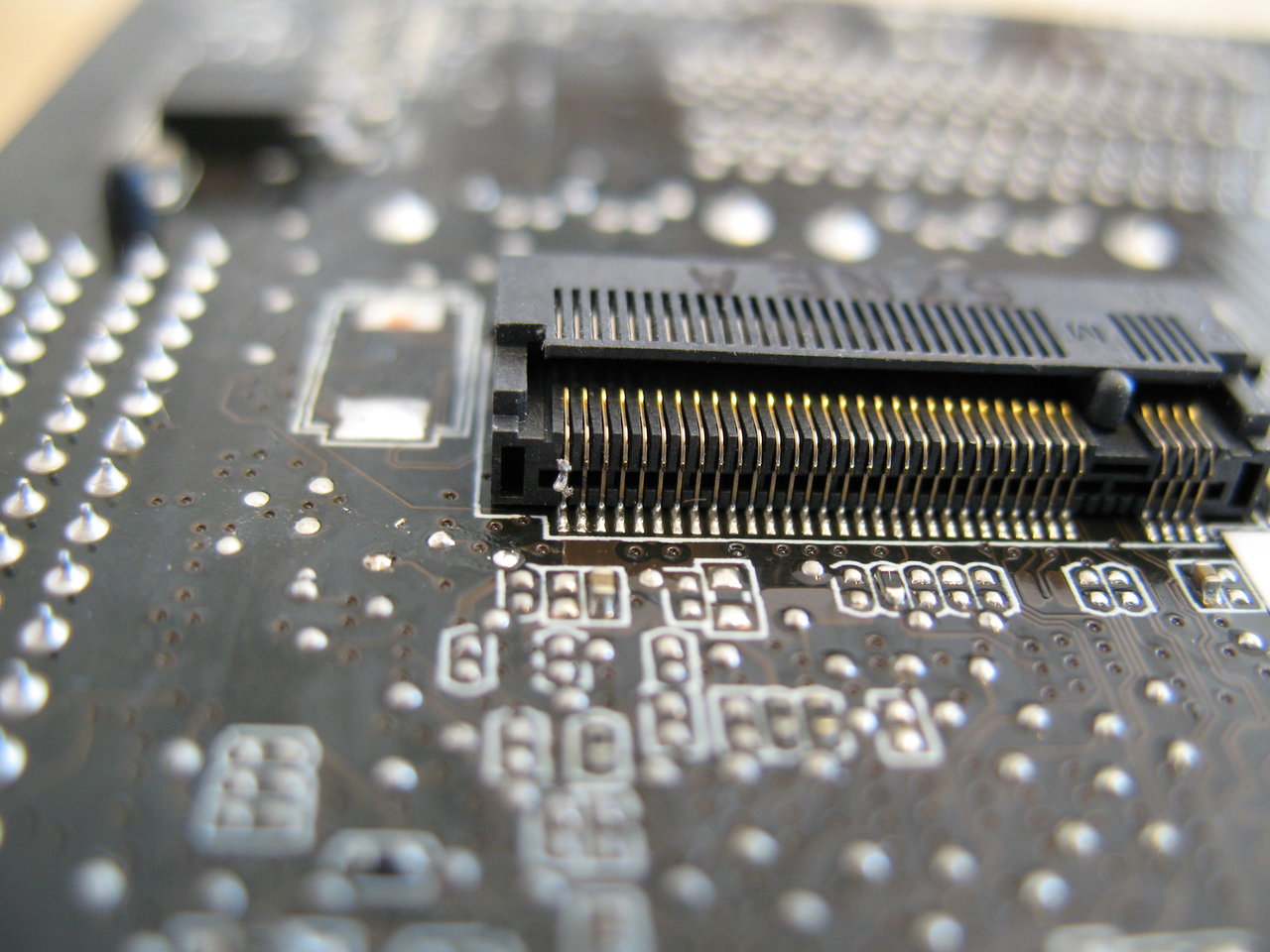
M.2 pin repair ?

Going to need higher res than you have there. You can drag and drop pics here.
 
It's hard to tell in the pic, but is the upper part of the blade soldered to the lower part that goes into the motherboard? If it is, it should be fine. Otherwise, you'll need to solder it. How this happened to just one pin is beyond me.

You can test it with a multi-meter that has a continuity function (beeps when the probes touch). Place one probe on the top of the blade, the other probe at the base.

But yes, you're right. This is just a GND pin - so it should work with the patch job from the factory.


Here's another angle, like the link above it's full resolution, without a camera set to macro you can't see detail let alone test or solder. I guess they have people at the factory who repair mobos that were damaged in the assembly line. But such miniature soldering is admirable, you can see a little blob of solder added to the broken pin.

You mean upper/lower blade? For a while I thought that the gold M.2 card contacts on either side went to different contacts, but it seems that they're both GROUND.

EDIT: This photo didn't come out full res, but the link above are full size if click on them.


IMG_8762.JPG
 
Last edited:
That's actually Pin-2, which is part of the +3.3v rail.

Should be okay, unless the computer is going to be in an environment that has lots of shaking/vibrations.
 
Back
Top