• Some users have recently had their accounts hijacked. It seems that the now defunct EVGA forums might have compromised your password there and seems many are using the same PW here. We would suggest you UPDATE YOUR PASSWORD and TURN ON 2FA for your account here to further secure it. None of the compromised accounts had 2FA turned on.
    Once you have enabled 2FA, your account will be updated soon to show a badge, letting other members know that you use 2FA to protect your account. This should be beneficial for everyone that uses FSFT.

Is there a molex-light controller/switch?, does this exsits?

Hitokiri Batohsai

Limp Gawd
Joined
Apr 22, 2003
Messages
429
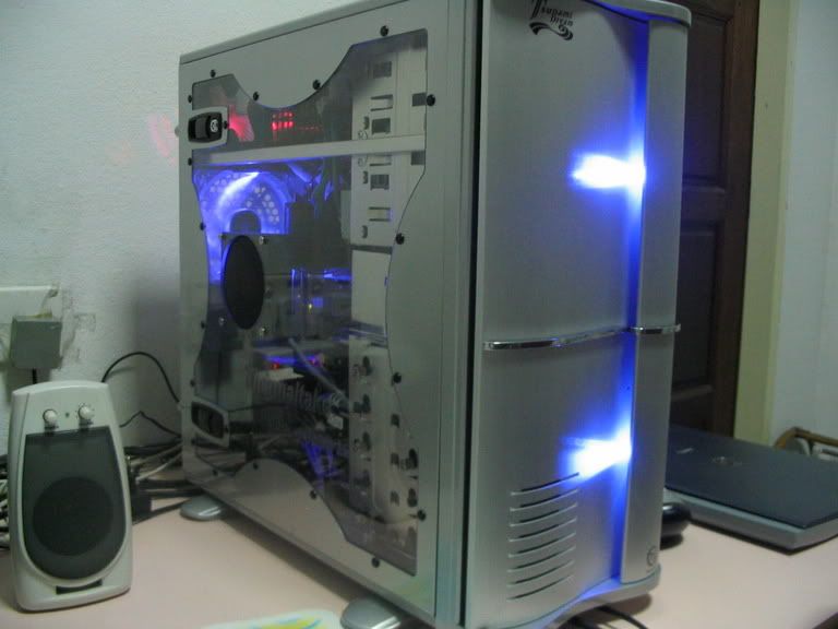
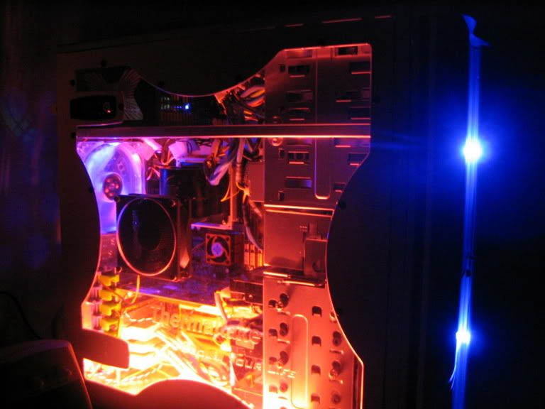
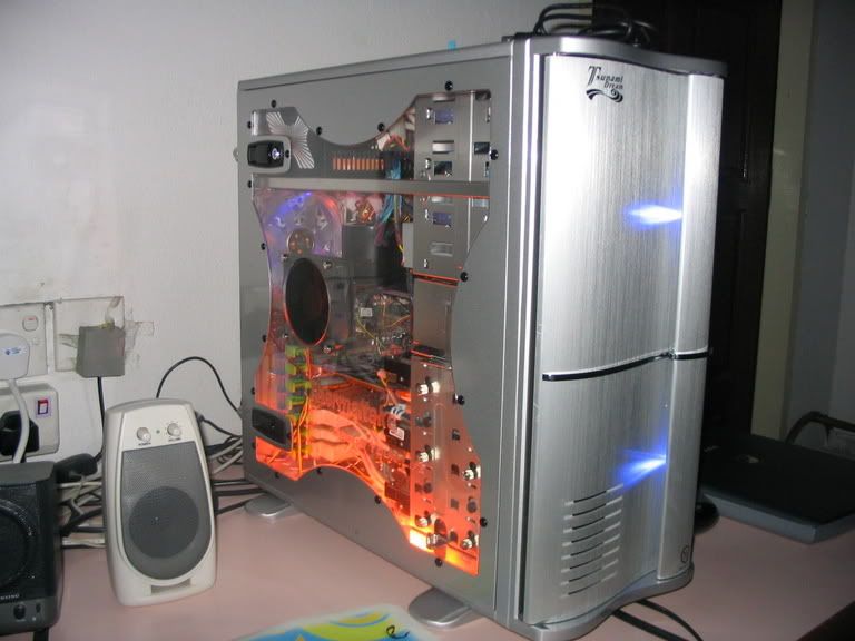
My pc has some lights, and there is no switch to this. The lights are connected to the molex connector, two wires protuding more to the lights.
Is there molex switch, controller that can just do the on/off function. So that I can turn on, turn off the lights whenever I want. I don't want to open the casing everytime to cabut, and sambung the damm molex connector.
if this type of connector does not exists, any other solution. I was thinking of going to the hardware shop, buying a normal flip on/off switch, cut one of the stray wires and placing it in between. There, easy light connector. But needs work. And also drilling one more of the floppy bays, to place the switch there.
Its a bit tedious.
Thanks
 
Yeah such things are out there. They are called a baybus. They can go from just switches to knobs and graphic displays. Here is just the first one I found this type is easily made. http://store.yahoo.com/xoxide/dualvol6porb.html Just need the switches, some wiring, a couple of LEDs, some resistors, and one of the covers from your floppy/cd drive. Just look around on some of the moding sites and you'll find a good few.

That one I just posted has 3 switch positions. On/Low/Off that is not good for your lights. Look or buy switches for just 2 positions
 
Thanks, other than a 6 baybus, I just need two, that fit into the floppy slot. And wires long enough to reach them. Thanks for the link. But I don't know how to use them, if they require any real wire cutting, know any sites that teach me to do so?

I foudn some abaybus, but all are the 51/4 bays. I could not find any floppy bays. If I can find just the switch, I am willing to drill the floppy cover.
 
Not many people make 3.5" switching fan controllers, most use rheostats so you can control the amount of voltage running to the target (usually fans)

I made my own bay bus using switches and a project box from radio shack, but it is much more complicated than what you need - I will draw up a diagram if you feel like building your own
 
you posted this in the modding forum... so obviuosly you would want to mod it yourself right???

;)
 
i got some rockerswitches from performnace-pcs for just this concern. I didn't want my lights on all the time. i fucked with the feed they had to the power, and put one line (red wire) to the middle prong of the rocker switch, and the other wire (yellow) to the bottom one. The switches i got have little blue leds in them as well so that when they're on, the LEDs light up. I opened up a black wire from a molex Y connector and tacked it to the top prong on my rocker switches...that give the rocker's LED juice when turned to the 'on' position. enclosed is a link to a pic i took when i was putting it together. hte switches are off but you see what I mean. If you're interested, lemme know via PM or something and i'll take some more pics and email them to you.

http://halogen.note.amherst.edu/~gcshaw/Dwayne/DCP_0182.JPG
 
Learning to solder is probably the best thing I've ever done for my electronics experience. It's handy- you could just pick up a DPDT switch from radio shack and solder it inline.
 
i made a switch fanbus from scratch it has a master switch for power to all fans and for each switch there is a green light to indicate 12v and a red light to indicate 7v... looking over my work i could have used a dual color led and done a better job around switches but meh it looks really fine to me ^.^
comp7.jpg

the switch thats all by itself above the usb ports are for my cold cathodes... you just wire it up in series to it breaks the circuit to the cathode inverter
 
Grizzy said:
Not many people make 3.5" switching fan controllers, most use rheostats so you can control the amount of voltage running to the target (usually fans)

I made my own bay bus using switches and a project box from radio shack, but it is much more complicated than what you need - I will draw up a diagram if you feel like building your own

Please do.

Yeah I posted here bacause I don't know if the switches exists, so I wanted to know. I just need switches.
All my 4 5 1/4 bays are full, after getting the hardcano 12. Thats why the other floppy is the only thing left. And cause this is a tsunami casing, I need low profile switches, if not I cannot close the case :p
 
Hitokiri Batohsai said:
Please do.

Yeah I posted here bacause I don't know if the switches exists, so I wanted to know. I just need switches.
All my 4 5 1/4 bays are full, after getting the hardcano 12. Thats why the other floppy is the only thing left. And cause this is a tsunami casing, I need low profile switches, if not I cannot close the case :p


OK - how many fans/lights will you want to control, how many switches, and if you are doing fans, do you want 12v/7v/5v?

I will post a drawing within 10min of seeing the answers to those questions - I will try to make it as cheap as possible for you (using the minimum number of switches, etc...) I will go to radio shack's website and pick out some possible switches for you and give you an estimate on price of the build (just because I am bored and am a nice guy)

Edit: also, how much clearance do you have between the bezel and the door on your case?

Second Edit: I got really bored and drew up 2 simple switch setups using a regular on/off switch and a on/off/on in the 5v/off/12v configuration drawn with molex connectors because that is how I made my can controller (I actually used RCA connectors), you can just use bare wires if you want and solder the switch in line with the lights or fan instead of using the connectors

On/Off switch setup:
switch1.jpg


5v/Off/12v switch setup:
switch2.jpg
 
Grizzy said:
OK - how many fans/lights will you want to control, how many switches, and if you are doing fans, do you want 12v/7v/5v?

I will post a drawing within 10min of seeing the answers to those questions - I will try to make it as cheap as possible for you (using the minimum number of switches, etc...) I will go to radio shack's website and pick out some possible switches for you and give you an estimate on price of the build (just because I am bored and am a nice guy)

Edit: also, how much clearance do you have between the bezel and the door on your case?

Second Edit: I got really bored and drew up 2 simple switch setups using a regular on/off switch and a on/off/on in the 5v/off/12v configuration drawn with molex connectors because that is how I made my can controller (I actually used RCA connectors), you can just use bare wires if you want and solder the switch in line with the lights or fan instead of using the connectors

On/Off switch setup:
switch1.jpg


5v/Off/12v switch setup:
switch2.jpg


Ok, I want to control the lights infront of my tsunami casing.
119_1982.jpg

Those blue lights
And
119_1975.jpg

Though the red CCFL does come with a sound sensor, so I can turn the sensitive of the sound to zero, so it wont light up. But I don't like to find the setting everytime I want to on it, thats why I'm thinking of a switch. I think that will work.
Head-space, less than 1cm. Like 0.8cm.
This casing has a weird door, once side having more than 3cm space, the other 1cm, due to the wave...yeah a CM wavemaster clone.
119_1973.jpg

I was thinking of using light switches, since knobs are a bit big.
 
So the 2 front lights are on the same power line right? Also, do you want them to turn on independant of the CCFL's or on the same switch as the CCFL's?

Edit: Are those LED"s on a 12v line or 5v line?

Double edit (I keep forgetting little things): do you want to use molex connectors or just solder the switches inline? If you want to put both devices on one switch I would use the molex connectors (can get them from an old fan)

Heres the drawing of that:
switch3.jpg


Assuming you already have a soldering iron and solder, wire from radio shack will cost a few dollars (you may already have wire) and switches will cost around $4 each for most of them, but this only costs $2.69 - I would have picked a lighted rocker switch to show you, but I didn't show the wiring for that in the drawing and am not positive on how those are wired
 
Hitokiri Batohsai said:
Ok, I want to control the lights infront of my tsunami casing.
119_1982.jpg

Those blue lights
And
119_1975.jpg

Though the red CCFL does come with a sound sensor, so I can turn the sensitive of the sound to zero, so it wont light up. But I don't like to find the setting everytime I want to on it, thats why I'm thinking of a switch. I think that will work.
Head-space, less than 1cm. Like 0.8cm.
This casing has a weird door, once side having more than 3cm space, the other 1cm, due to the wave...yeah a CM wavemaster clone.
119_1973.jpg

I was thinking of using light switches, since knobs are a bit big.
i think you should add a fan grill to the side fan
 
Grizzy said:
So the 2 front lights are on the same power line right? Also, do you want them to turn on independant of the CCFL's or on the same switch as the CCFL's?

Edit: Are those LED"s on a 12v line or 5v line?

Double edit (I keep forgetting little things): do you want to use molex connectors or just solder the switches inline? If you want to put both devices on one switch I would use the molex connectors (can get them from an old fan)

Heres the drawing of that:
switch3.jpg


Assuming you already have a soldering iron and solder, wire from radio shack will cost a few dollars (you may already have wire) and switches will cost around $4 each for most of them, but this only costs $2.69 - I would have picked a lighted rocker switch to show you, but I didn't show the wiring for that in the drawing and am not positive on how those are wired


The two lights are on the same line. How do I tell if its a 5v/12v?
The CCFL is independant, another molex,
I plan to have two switches, one for the two LEDs, the other for the CCFL. So which one is better, solder, or cut, twist and tape.
So I follow the second diagram right?

The link you gave me, yup, that is the switch I had in mind. Just like the switches of the power plugs.

About the grill, well there is already one for the side fan, and its protuding outward, in a dome fashion. If I place a grill, which I can, it will scratch the glass marks on the top, since the glass is the top surface. The present grill is already trapping more dust. I have a casing with a grill before, the grill seems to carode away, or change color, dust sticking there, so I don't like it.
Thanks
 
The diagram in my last post is the one you want to follow, and I would reccomend using connectors and soldering them with heatshrink for the best safest connection

You can find out if the LED"s are 12v by finding the power line to them and seeing where it goes. If you arent sure still, give them 12v just for a second (if they are 5v or lower, any more will kill them) and see how bright they are. If they are normal brightness, they are just 12v LED"s - if they are anything else, find out what it is and I will draw up another diagram for it

You can get the connectors from old fans or whatever, but it will be worth it in the end. I also suggest putting that setup in some kind of project box or at least have solid mountings for the switches and molex connectors so nothing just flops around
 
dwayne001 said:
i got some rockerswitches from performnace-pcs for just this concern. I didn't want my lights on all the time. i fucked with the feed they had to the power, and put one line (red wire) to the middle prong of the rocker switch, and the other wire (yellow) to the bottom one. The switches i got have little blue leds in them as well so that when they're on, the LEDs light up. I opened up a black wire from a molex Y connector and tacked it to the top prong on my rocker switches...that give the rocker's LED juice when turned to the 'on' position. enclosed is a link to a pic i took when i was putting it together. hte switches are off but you see what I mean. If you're interested, lemme know via PM or something and i'll take some more pics and email them to you.

http://halogen.note.amherst.edu/~gcshaw/Dwayne/DCP_0182.JPG

That's funny, because that's exactly how mine is set up -- as least for the visual. Silver case 3.5" bay, 3 of those exact switches side by side.
 
Grizzy said:
The diagram in my last post is the one you want to follow, and I would reccomend using connectors and soldering them with heatshrink for the best safest connection

You can find out if the LED"s are 12v by finding the power line to them and seeing where it goes. If you arent sure still, give them 12v just for a second (if they are 5v or lower, any more will kill them) and see how bright they are. If they are normal brightness, they are just 12v LED"s - if they are anything else, find out what it is and I will draw up another diagram for it

You can get the connectors from old fans or whatever, but it will be worth it in the end. I also suggest putting that setup in some kind of project box or at least have solid mountings for the switches and molex connectors so nothing just flops around

Thanks. The brightness, is very bright.
Make everything in a box, something like the thermaltake hardcano, coming in a box. Now I need a box. The power line to the LEDs go to the LED. I don't understand that part. I just take one of my molex from the PSU, and hook it up.
 
Hitokiri Batohsai said:
Thanks. The brightness, is very bright.
Make everything in a box, something like the thermaltake hardcano, coming in a box. Now I need a box. The power line to the LEDs go to the LED. I don't understand that part. I just take one of my molex from the PSU, and hook it up.

I meant from the LED to what - as in what does the other end plug into to get power? Red wire or yellow? Yellow is 12v so you will be able to use my diagram. If it goes to the red wire in the molex, the diagram will have to be changed a little
 
Grizzy said:
I meant from the LED to what - as in what does the other end plug into to get power? Red wire or yellow? Yellow is 12v so you will be able to use my diagram. If it goes to the red wire in the molex, the diagram will have to be changed a little

Ok, I will check and get back to you
 
Here are the wires:
For the front lights-1 wire.
It connects to the molex at the red and black wire.

For the CCFL,
it connects to the molex at the yellow wire.

Things I need for modding are:
molex wires.
switches
drill,some way to make a hole. But I don't have a clamp to hold the plastic, even if I did, there is no place to mount it to. So this is a problem when drilling.
Solder?do I need this.
Anymore that I need for this job?

I went to the store to get the switch, I forgot if the switch is AC/DC. The switch is AC right? I forgot. For the same switch(like in the picture), it cost $0.10. After currency exchane.

But the swtiches has three metal feets/connectors. Which type of connector should I get?

Also when drilling through plastic, I am just afraid the plastic will just break to pieces. Would this happen? I also forgot to bring the drive bay to measure how much.

What is the best way of joining this new wires to the molex connector?

Thanks. I hope to make it a weekend project, around 3 hours or less.
 
Computers are DC power, and you will want a switch with only 2 poles on it (unless it lights up, but I don't know the voltage specs on those so I won't show you how to wire them)

You will want one switch with the 12v+ yellow wire running in and out, and one with the 5v+ red wire running in and out - Same as the drawing, but using 2 switches, different color wires
 
There is a 12v switch. And I think A 5V is available.

I have the switches. There was no 5v switch, so I got the 3A 250V with two feet. Basic on/off switch.
there is also a 12V dc 10A switch, with three feet.
 
There is something wrong, I did the connections all, when I try to plug it in, the pc would not start, it just died. I tried it while it was on, same thing, the connections I follow the diagram. Whats wrong here?
 
Hitokiri Batohsai said:
There is something wrong, I did the connections all, when I try to plug it in, the pc would not start, it just died. I tried it while it was on, same thing, the connections I follow the diagram. Whats wrong here?
probably a loose connection

i did a thing in the bay drive with cutting a blowhole on two cd drive bay covers and putting a switch and led in... kinda like what you're doing here but a lot simpler and when i finished and plugged it in, it wouldnt work... i realized it was just bad connections and if i jiggle the switch a lil, it lights up... so i just resoldered the switch and now it works great

btw, a bad connection is just an idea... first thing that popped into my head, that might not even be a problem but you might wanna check your soldering to make sure
 
I am not sure, but connections seem solid to me.
Situation 1:
the pc is on, PSU running, I just connect the wires, the whole system shuts down. I tried to turn on the system, it would not turn on until I unplug the connections I made.

Situation 2:
off pc, connect everything first, PC would not start up. I need to unplug the connections then it will start up. I tested the connections first before drilling any hole in the drive bay. I am not sure which switch I will be using.

Also, grizzy, is that diagram correct? I am doing the front lights now, which are red, black wire. So I cut the red and yellow wires and place a switch in between.

MOLEX IN:yellow-------cut--switch--cut-----yellow:MOLEX OUT
black---------------------------black
black----------------------------black
red----------cut--switch--cut------red
 
Back
Top