Help with a very unusual schematic symbol

starhawk

[H]F Junkie
Joined
Oct 4, 2004
Messages
8,908
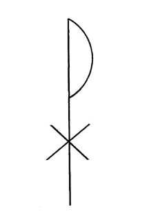
Trying to figure out what this is (picture below). It's part of a circuit to get a 78xx to output negative voltage. (Don't ask. It's complicated!)

Of course there's no part number or value for it...

What the CRAP is this device?

5jI5xNk.png


It's in this datasheet, page 26 --> http://www.fairchildsemi.com/ds/LM/LM7805.pdf
Circuit is predictably named "Negative Voltage Output Circuit" and is Figure 18.
 
I can't remember what the symbol represents, But I can't help asking;why not use a fairchild 79xx,which has negative output?
 
I don't know how to use a 79xx and I don't know where to get one. I suppose Mouser probably stocks 'em. They're also likely to be more expensive than a 78xx -- which is a problem for me.

Basically here's what's going on --

I have a PowerTip PG128128A LCD. It's a graphic LCD, monochrome, 128px square. IIRC it's STN. Ugly-ass yellow-green backlight. Yeah, it's a little old :p Controller is some wierdass Toshiba thing I've never heard of. It's certainly not a common controller.

The datasheet lists the connections (poorly) for the 20pin header and the separate 2pin backlight header. Nice, but it doesn't list the contrast voltage. Did some googling around and found this thread here from 8+ years ago (!) which answered my question on that.

I want to run this thing off a 6v battery, specifically 4 AAs. There will be an Arduino chip in the mix as well -- yes, I know I need a separate 78xx for that, so that it's getting 5v and not 6v. That's not an issue.

So what I'm trying to do is make a negative 12v supply. I've found an only-slightly-more-expensive-than-I'd-like DC voltage doubler on eBay (it's $5.75+$2.95 shipping, but it seriously beats losing hair trying to design my own) so that takes care of making the 6v supply into 12v -- but then I need a negative voltage out of that, for the contrast, as well as a 5v positive voltage.

There are a couple 555-based negative voltage sources out there... but they're all limited to 50mA and I'm honestly not sure that's enough. I don't want to risk it -- since it could probably cook both LCD and 555 if that's not enough -- so I figured I'd just use a 7812 and that circuit in the datasheet.

Now if only I knew what component that was so I could get this design going...
 
Ground loop? Farady cage?

I saw this schematic symbol the other day and I'm scratching my head on how it achieves it's potential??

PL4A.jpg

LOL

OP, I've got a brother who eats electric schematics with milk for breakfast. I'll run it by him.
 
7912 will not work for me -- it requires a negative voltage input as well as a ground input.

I need to take a positive voltage and make it negative.

Back to square one.

EDIT: dunno if this helps, but here is the datasheet for the LCD I'm working with --> http://www.powertipusa.com/pdf/pg128128a.pdf
Worst effing datasheet I've ever tried to read. "Vo" is labeled as contrast on the pinout (with no explanation of acceptable values whatsoever), and there's also a "Vee" mentioned with no definition and a "Vop" that is mentioned with a definition but no explanation of how to use it. Unless there's a typo and Vo = Vop. Further, there's a spec for an "LCM current consumption"... what the crap is an LCM? They top it all off by mentioning "LCD driving supply voltage" but don't explain whether that's Vo, Vop, or some third thing that's also undefined. At least I didn't spend much money on the display... it was IIRC $6, shipping and all. Go eBay :rolleyes: *sigh*
 
Last edited:
Sent an email to PowerTip USA --

Hello!

I have a PowerTip PG128128-A graphic LCD. I'm quite sure it's quite old, but I'm hoping you can help me with some things that aren't adequately explained on the datasheet.

(1) Pin 4 on the connector is labeled as "Vo" "Contrast Adjust" but no voltage or current rating is given. Can you provide me with this? (This is *extremely* important to me -- if nothing else, I need this!)

(2) What pin(s) do the items "LCD driving supply voltage" and "LCD operation voltage" pertain to or affect?

(3) What is the rating and connection for Vee?

(4) What does "LCM current consumption (No B/L) refer to? Assuming that this refers to the consumption of the entire PG128128-A module, is that per pixel on the display, or overall?

(5) I assume it's safe to connect the Frame Ground (Pin 1 on the connector) to the signal ground (Pin 2)? If not, should I leave it floating or connect it elsewhere (please specify)?

(6) I see, on the datasheet, that the LED backlight voltage is supposed to be 4.2v -- is it safe to connect that to 5v or will doing such destroy the backlight fairly quickly?

Thank you!

Their website contact form doesn't work (!) so we'll see if they bother to respond... it didn't bounce instantly, though, which is a fairly good sign.
 
He just got back to me on it.
it is a specific polarized capacitor and what he is looking for is listed in the schematic on. www.fairchildsemi.com depending on what part of the schematic he is looking at it could be one of the following. 470uF, 2.2uF, 1uF however he is wanting the Negative output schematic from what I can see from HardOCP he would need a 10uF polarized capacitor. They are the electrolytic caps with Positive+ negative- markings on each side and are usually black and aluminum.

734118_618385471520996_1827221960_n.jpg
 
Thanks, man!

See post above mine, I think I beat you to it a little. It's good to know the value tho ;)
 
starhawk, if you're looking for cheap LCDs for doing cool stuff, you may want to look into "nokia 5110" modules. They're super cheap (~$3.50 on ebay), have a nice, convenient 0.1" pin header, and run off 3.3V. They're also VERY well documented.
 
...and the PCBs are too thin, and within two months they're dead because the little conductive rubber doohickey that goes from board to LCD bends the board and breaks the connection. The problem is terminal because of how the LCD is tacked down, too...

This issue is well documented on SparkFun's page for that product, in the ginormous comments section. I read the whole thing. It affects ALL of those LCD modules, not just SparkFun's variety ;)

EDIT: by the way, Mohonri, looks to me like you're not as active as you used to be -- at least here in Electronics. Hope nothing bothersome is going on...
 
Last edited:
Nope, nothing wrong--just super busy with life! I'm still here every day or so.
 
Back
Top