• Some users have recently had their accounts hijacked. It seems that the now defunct EVGA forums might have compromised your password there and seems many are using the same PW here. We would suggest you UPDATE YOUR PASSWORD and TURN ON 2FA for your account here to further secure it. None of the compromised accounts had 2FA turned on.
    Once you have enabled 2FA, your account will be updated soon to show a badge, letting other members know that you use 2FA to protect your account. This should be beneficial for everyone that uses FSFT.

Flow meter application with real-time flow readout

Rezistor

Limp Gawd
Joined
Dec 29, 2001
Messages
459
Hello all. Some time ago, I posted a thread where I first used a Proteus flow meter connected to a panel meter that showed the flow through the loop. Well, since that time, I had a misfortune of shorting out that particular flow meter.

Some time ago, I acquired a new generation of these flow meters, and revived my plans of installing a flow meter again in my system. Since I am running two loops, I upgraded my previous design to be able to handle input from two flow meters. So far, the system has been tested outside the computer, here are some pics.

The flow meter, made from stainless steel, with 1/2" ID barbs

01_resize.jpg


It has connections for voltage output proportional to the flow, relay contacts that can be triggered by an adjustable trip-point, and green/red status LEDs

02_resize.jpg


While polishing

03_resize.jpg


Finished

04_resize.jpg


05_resize.jpg


The complete setup, including the flow meter, junction box, and the panel meter with LEDs and switches for two alarms (activated by the trip-point)

06_resize.jpg


Junction box that takes input from two flow meters and sends them to the panel meter

07_resize.jpg


09_resize.jpg


Panel meter in OK state. Note the green LED indicating flow above the trip-point. The meter shows flow in GPM.

10_resize.jpg


Flow at the trip-point. Both LEDs are ON, but no alarm.

11_resize.jpg


Flow below trip-point. Red LED is ON, as well as the buzzer alarm. The switches with blue LEDs turn off the buzzer.

12_resize.jpg


The beauty of this panel meter is that besides being a regular voltmeter, it has an option to scale the output. Since the flow meter outputs 5V DC at 4.5GPM, I can set the panel meter to show "4.5" when it is receiving 5V DC.

What do you guys think? I know the system is quite bulky, especially with the weight of the stainless steel flow meter that can not be supported by tubing alone. On the upside, it does offer the ability to monitor the flow, as well as activate the alarm and possibly shut down the PC if the flow drops below a certain value.
 
On the upside, it does offer the ability to monitor the flow, as well as activate the alarm and possibly shut down the PC if the flow drops below a certain value.

Mk, I give it points for ingenuity. However, AquaComputer already has this implementation in a nice and neat little package with their Aquaero™ and Flow Meter. I run it and it gives me the constant and real time status of flow in my loop AND it has an active shutdown feature that lets you set the parameters. Yours seems like a good less expensive alternative though.
 
Mk, I give it points for ingenuity. However, AquaComputer already has this implementation in a nice and neat little package with their Aquaero™ and Flow Meter. I run it and it gives me the constant and real time status of flow in my loop AND it has an active shutdown feature that lets you set the parameters. Yours seems like a good less expensive alternative though.

QFT
 
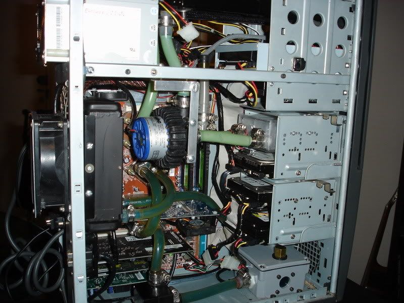
I'm back, and I bring you lots of pics of the flow meter installed in my (by now) antique case. I have to publish a warning - what you are about to see may trigger powerful emotions of confusion and even anger. Many will say that there is absolutely no point in updating a 5-year old machine that is still running on nforce2 motherboard. Well, I am doing all of this, just as I do anything else to my computer, out of sheer enthusiasm and modding spirit, this is practically the only opportunity for me to use my tools and come up with solutions to arising problems.

OK, here we go. Out with the old. Notice the nice green build-up on 7/16" ID Masterkleer tubing after a year or two of use. That residue could be partially removed by lab-grade acetone.

01.jpg


02.jpg


I needed to create a bit more space in the center of the case, so I designed a new mounting bracket for the pump and moved it closer to the 2nd radiator.

03.jpg


The Proteus flow meter that I'm using has 7/16"-18 SAE threads, which are mainly used on hydraulic equipment. The fittings that you can see in my initial testing are actually DangerDen's Hi-Flo fittings that, by pure chance, had the thread that I needed. Unfortunately, due to the extremely cramped conditions inside the case (as you will see), I needed angled barbs. After doing a lot of searching and not finding what I needed, I decided to make my own. I mated a 3/4" barb elbow (Loew's home improvement) to the stainless steel hydraulic fitting that came with the meter (basically forcefully threaded the stainless steel fitting into the brass elbow). Since the hydraulic fittings had a pretty narrow ID size, I first drilled them out (on the top, you can see before and after drilling out, and on the bottom the assembled elbow).

05.jpg


04.jpg


Since the entire flow meter is made from stainless steel and is quite heavy, I designed a simple bracket that bolts to the rail of the case and supports the weight of the flow meter.

06.jpg


Everything connected. There were no leaks during the testing, and you have no idea how happy I was, as disassembling this jumble of parts and tubing would be a nightmare.

07.jpg


08.jpg


...and done!

09.jpg


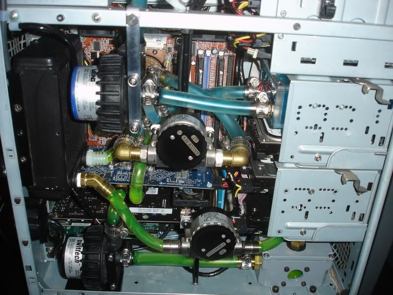
Due to extemely short lengths of tubing used in my loop (reservoir => D4 pump => 2x120 BlackIce radiator => Maze4 CPU waterblock => Proteus flow meter), I am able to get close to 2 GPM flow, which is more than enough.

10.jpg


11.jpg


Well, this is how the computer sits right now. I am thinking of installing the second flow meter into the GPU/Northblock loop, since my flow monitoring system can read from two flow meters.

Thanks for your time! Hope you enjoyed the ride.
 
Updates!

2flowmeters1.jpg


2flowmeters2.jpg


2flowmeters3.jpg


2flowmeters4.jpg


2flowmeters5.jpg


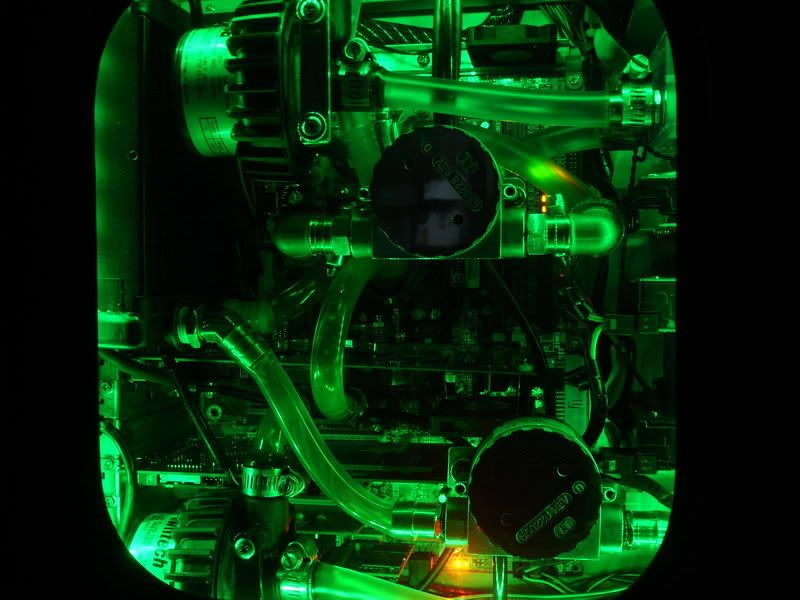
As you can see, I installed the second flow meter into the GPU/Northbridge loop powered by a small CSP-MAG II pump. While the CPU loop, powered by a Laing D4, is getting 1.98 GPM, the GPU/Northbridge loop is getting 0.48 GPM. Maybe I will upgrade the little pump to another D4/D5 in the future.

And the only way to reach anything inside the case is done using tweezers.
 
Final update, at least it looks like one. Acting as a self-fulfilling prophecy, the little CSP-MAG pump died shortly after I completed the previous update, and I finally replaced it with a D5 pump. Getting close to 2GPM on the CPU loop, and 1GPM on the GFX/Northbridge loop (running the new D5 pump on setting 3).

2pumps2meters01.jpg


2pumps2meters02.jpg


2pumps2meters03.jpg


2pumps2meters04.jpg
 
You're one crazy dude.
I must give you insane credit for quality engineering though, good job!!
Those are possibly the shortest loops I've ever seen.
 
I am totally agree with my friend MEZZ. Man it is good looking loop, and definately shortest one too.

So you are saying Swiftech's pump is slower than D4 ?
 
While the Aqua Computer and Innovatek water cooling electronics are great for low flowers, this unit may get the high flow crowd out into the flow monitoring scene. Very nice integration of electronics and mechanics. :D

So why don't you either supply us with the schematics or produce a kit for sale?

Looks like 90 and 45 degree elbows don't make a hill of beans difference in this unit. 2 GPM is way more than you need for adequate cooling performance. ;)

Does your pumps have the adjustable pump gizmo?
 
Regarding the pumps, the D4 I am using for the top CPU loop has been with me for several years, and does not have the speed control built in. I can, however, throttle this pump manually with a 20-watt 10-Ohm (if I remember correctly) poterntionmeter, but right now that pump is running full speed. The new Swiftech/D5 pump is running on setting 3 because when I inially was filling the loop, it was making high-pitched noise due to bubbles suspended in the water (being sucked in from the reservoir). After the bleeding was done, the noise was gone, but as you can tell, it was a pain to get to that little adjusting knob at the rear of the pump, so I just let the pump run at that speed. The flow is not the limiting factor, it's the single 120mm radiator.
 
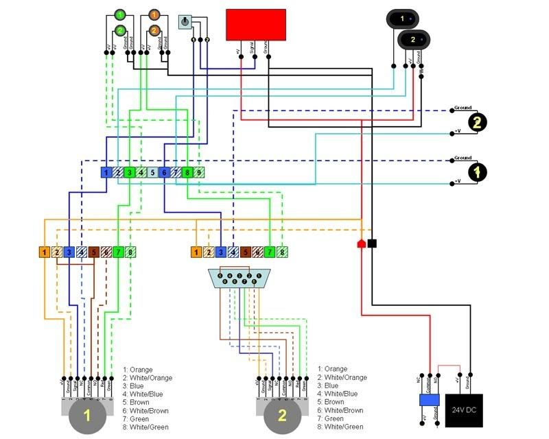
And this is the wiring diagram that I used to connect the two flow meters to the junction box that contains two piezo alarms. The junction box relays the power to the status LEDs from each flow meter, and also the flow signals to the panel meter.

WiringDiagramresize.jpg
 
Wow, the schematic is much simpler than I expected. Looks great.

Quick question: do you think you would have gotten better temps by just buying a new block than all this short-loop-insanity (though I do like it!)?
 
I cringe at the thought of you having to replace your motherboard...

Where'd you get the flow meters :D

Wouldn't you want to electrically isolate the meter from the case to prevent corrosion, there's about a -.2v differential between copper and SS :eek:
 
I have been running stainless steel parts in my previous loop configurations with no apparent signs of corrosition that I could see inside the waterblocks, granted I used a small amount of Zerex corrosion inhibitor in my deionized water. And as far as waterblocks go, I am certain I could get better performance with one that's newer than the Maze4, but you gotta keep in my mind what hardware I am watercooling here - Athlon XP mobile running on a nForce2 motherboard. This system is fit for a museum exhibition as far as computer hardware goes, so there's no point of further investing money into this ageing machine.
 
Back
Top