External watercooling box project

Joined
Oct 2, 2003
Messages
2,173
Well, I've been working on this project on and off for the past month or so, so I decided to create a worklog.

To sum it up, I am building an external w/c box that will sit on top of my case. Inside it will have dual radiators, a pump, a res, fans, and a fan controller.

I haven't finished a ton yet as I have been trying to carefully plan things out (I am a metal-working newbie) but at least it looks like I am getting somewhere.

Here is a rough autocad picture of what I am doing on the inside, although I have flipped the radiators and moved around some components in the final design.

my.php


Here is the list of parts:

Eheim 1250
77' Bonneville heater core
86' Chevette heater core
D-tek Whitewater CPU block
D-tek GPU block w/ homemade adapter for 6800 GT
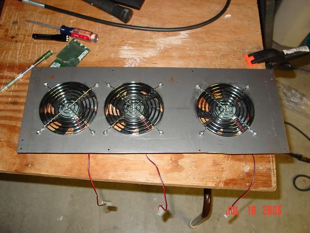
3 Panaflo U1A fans
Plexiglass shroud for the bonnie core from a previous project
36'' x 48'' sheet of 22 AWG steel
8'' x 18'' sheet of 22 AWG steel
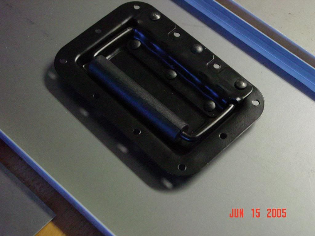
1 Zinc plated recessed handle (I love this thing)
16' of angled aluminum for the frame
Some aluminum mesh
Other misc stuff (black car paint, primer, screws, rivets, etc)

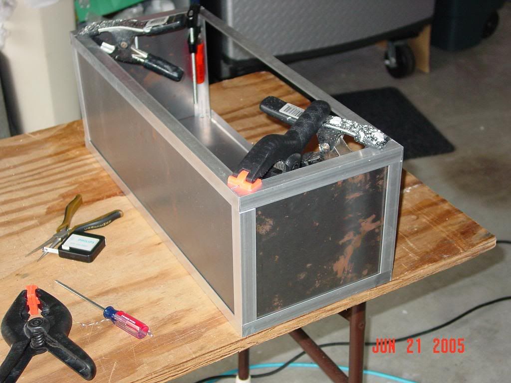
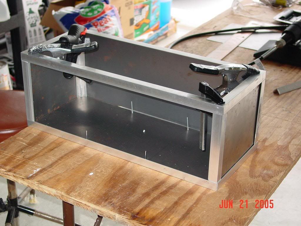
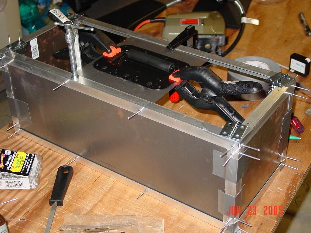
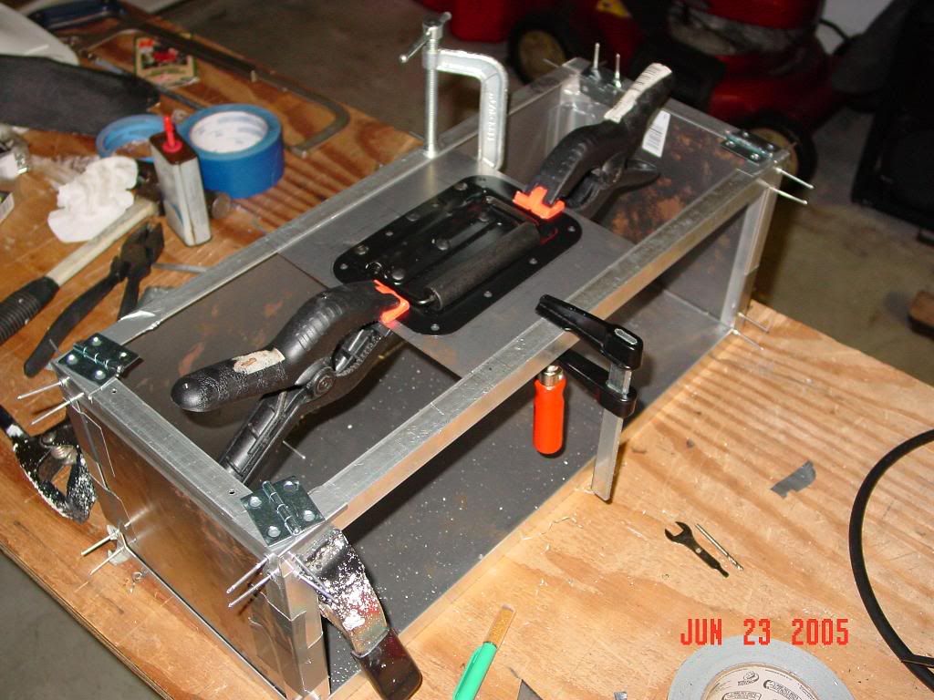
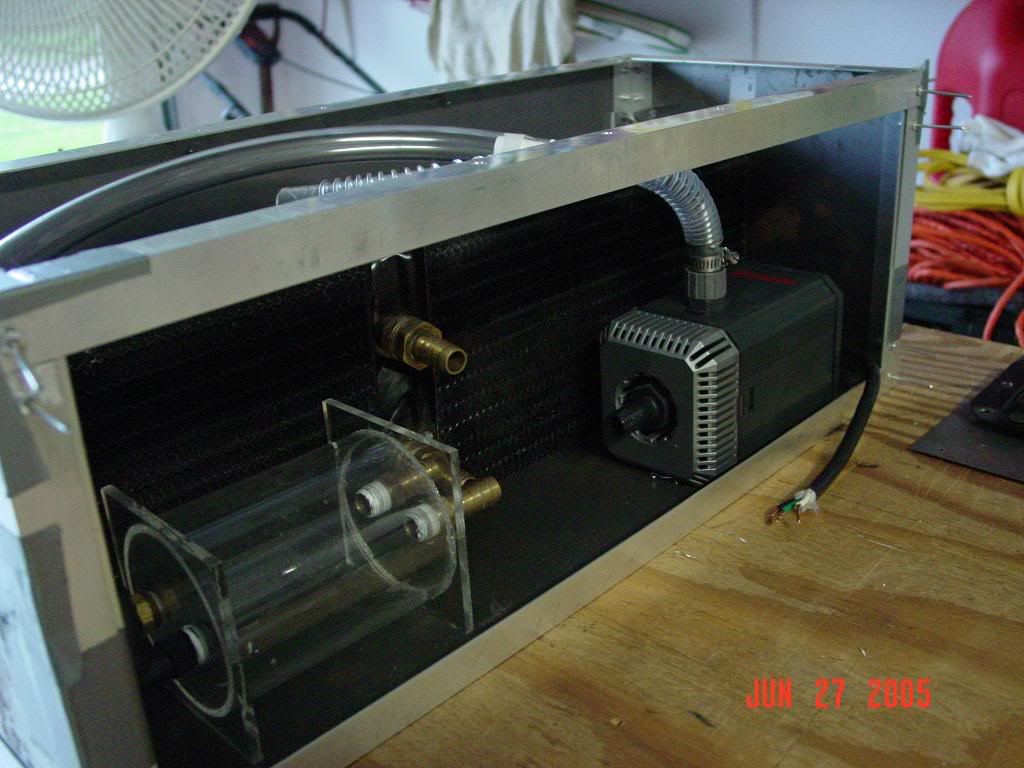
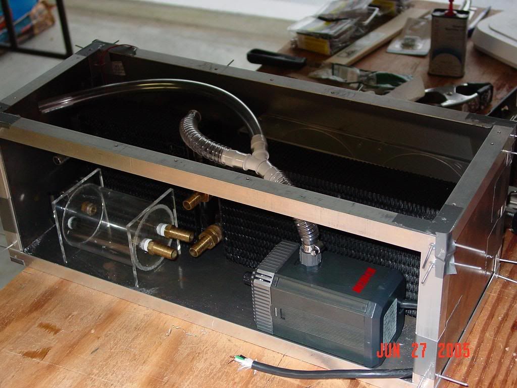
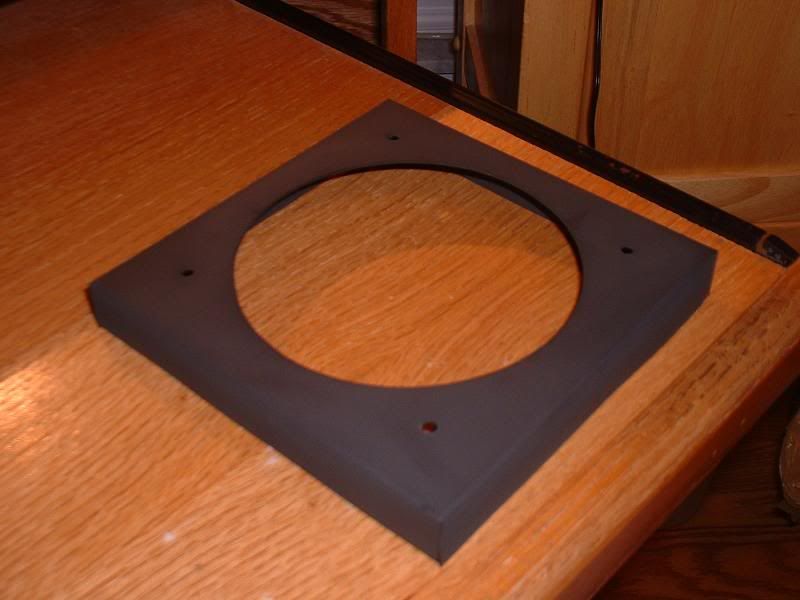
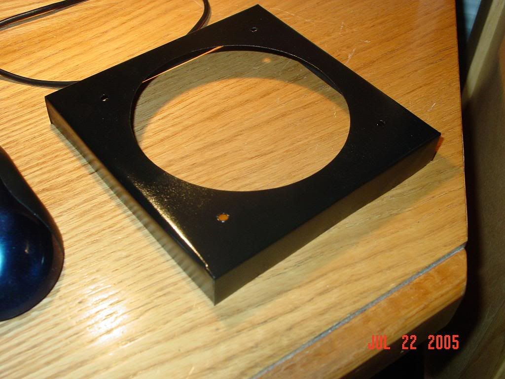
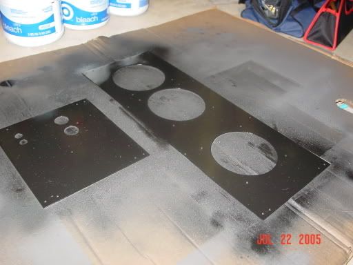
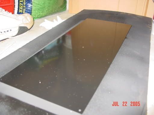
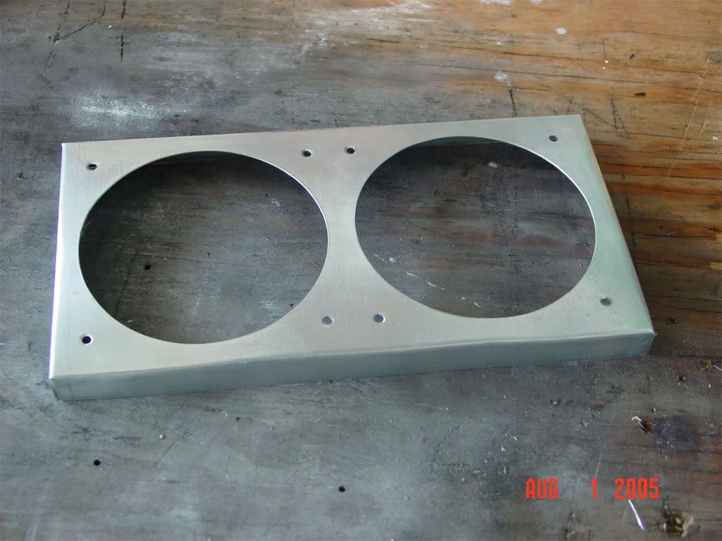
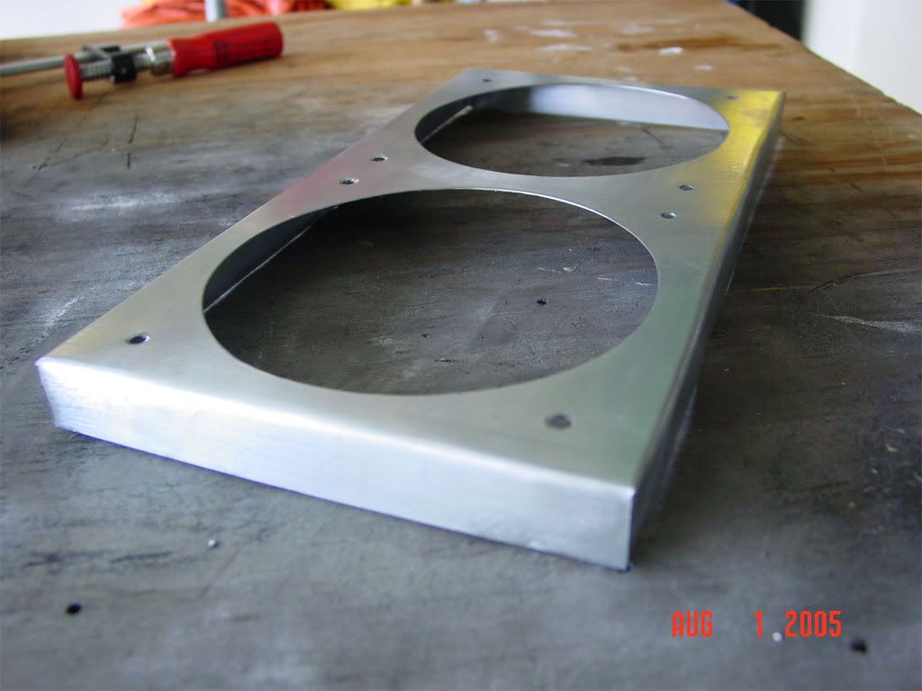
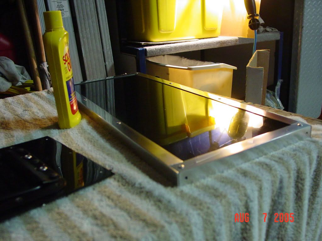
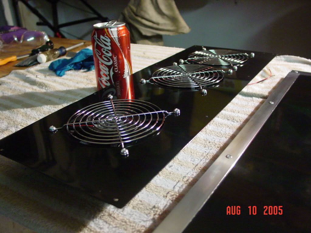
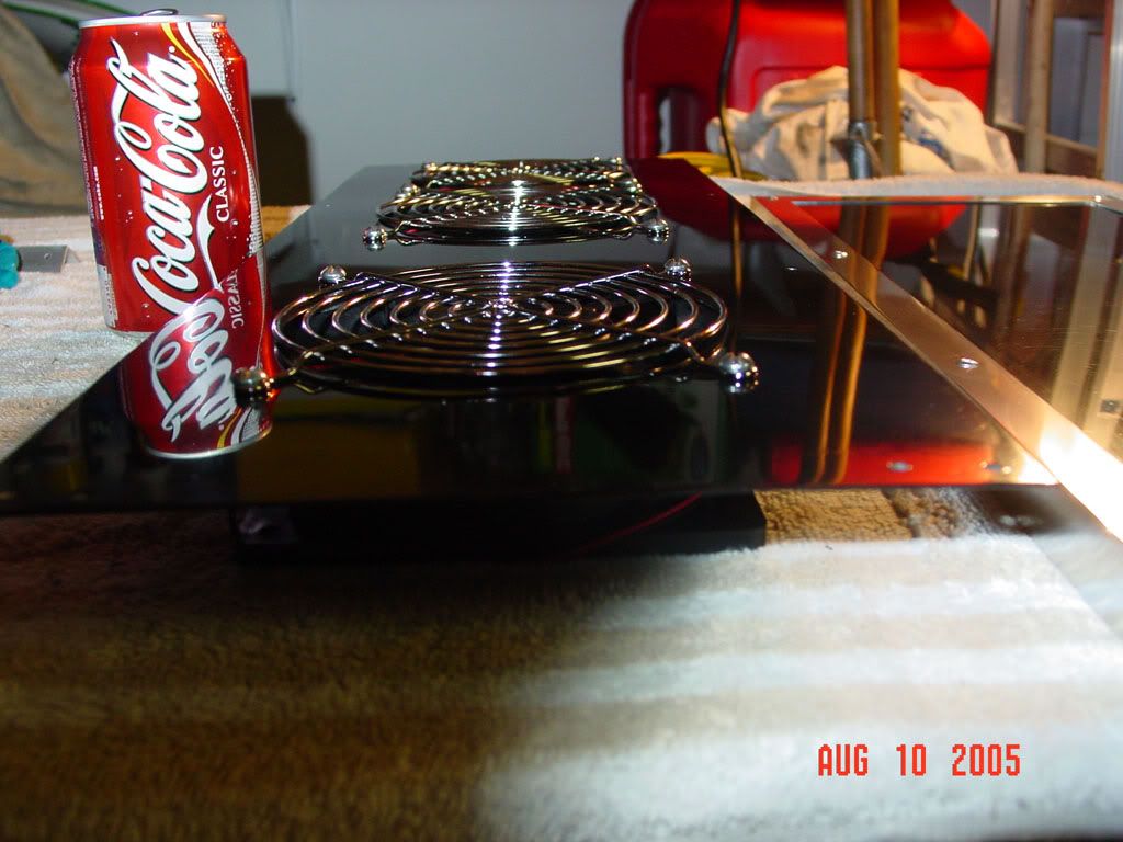
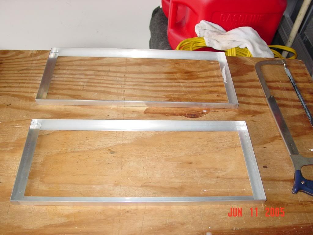
Anyway, here is a pic after I made the top and bottom frame:

DSC01332new.jpg


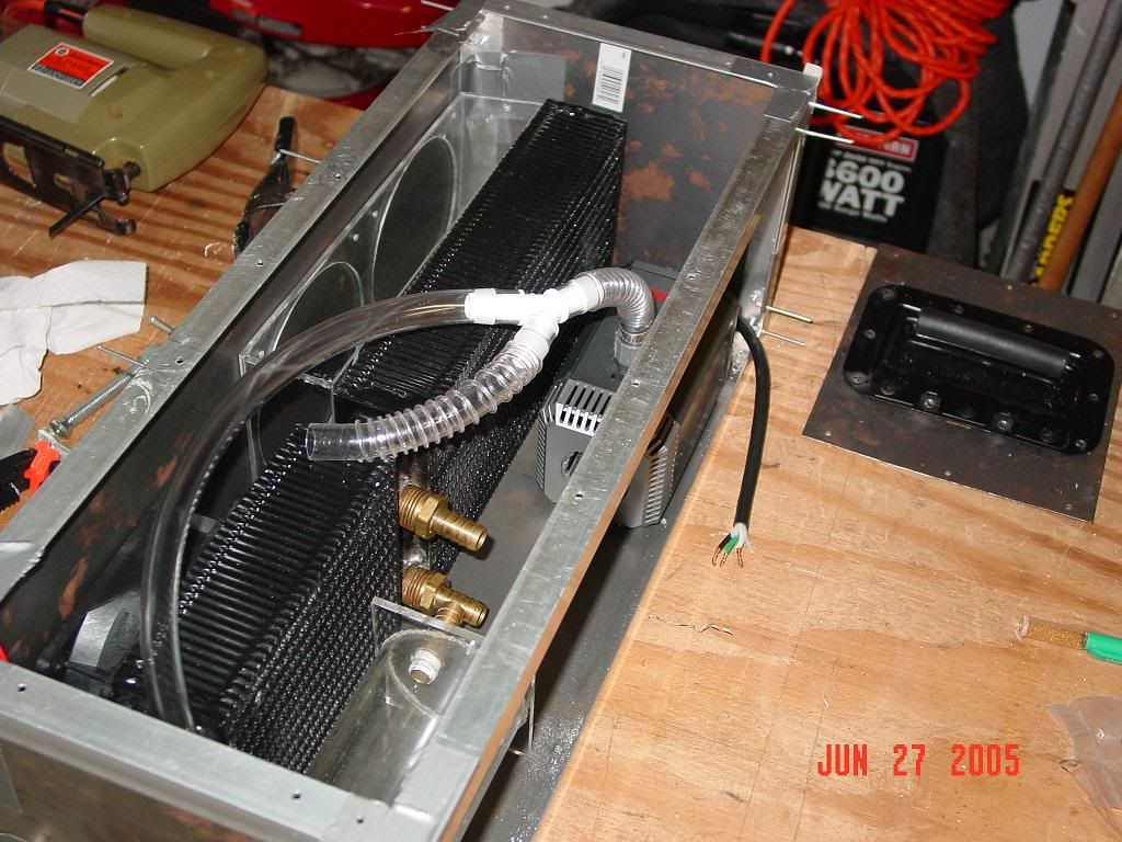
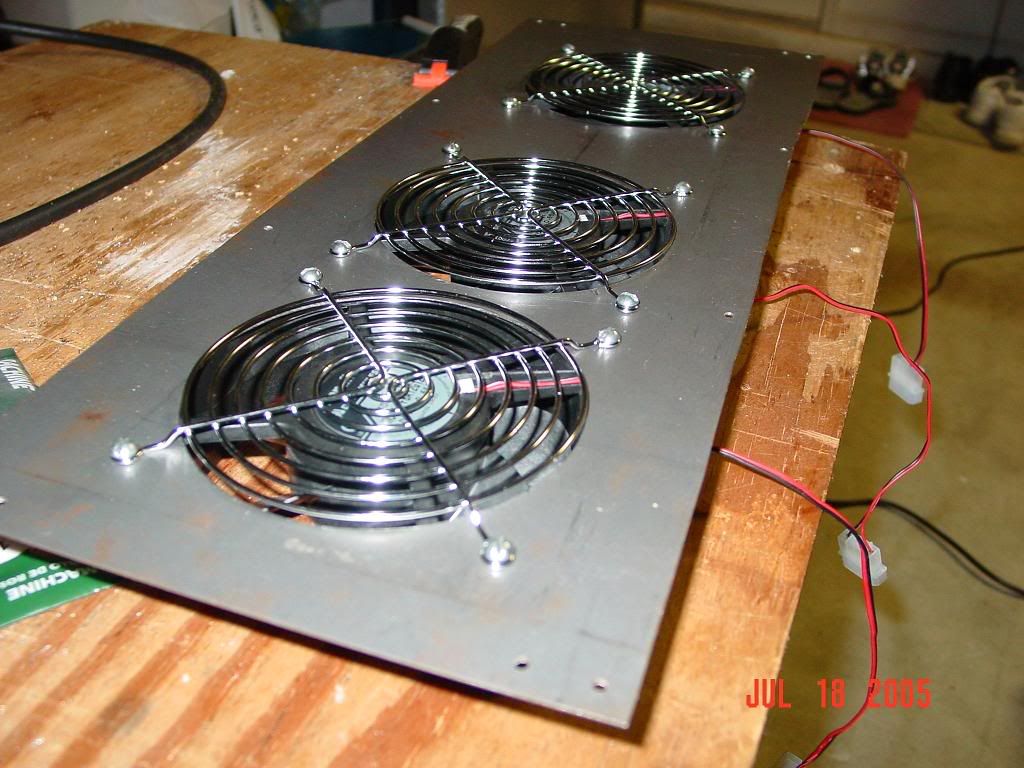
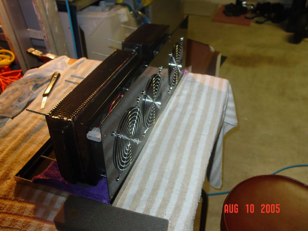
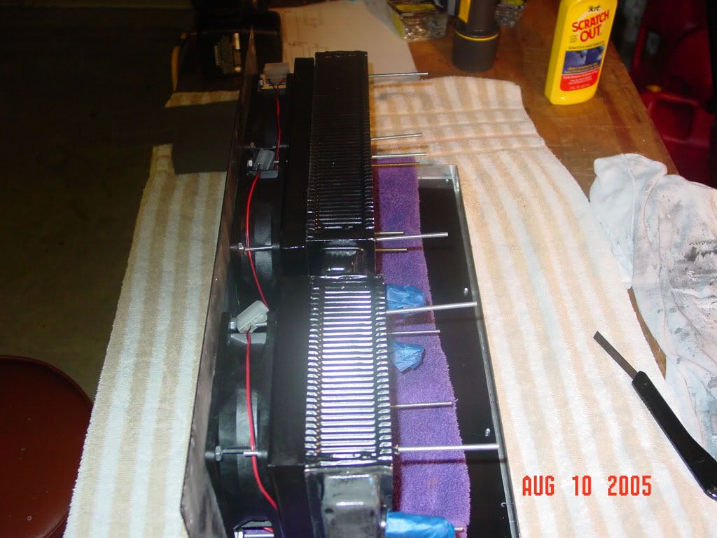
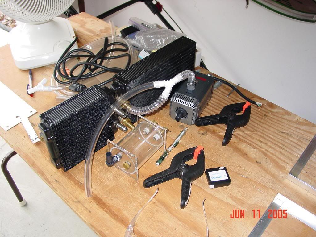
Some of the inside parts, half put together. I decided to finish assembly one the box is completed - it makes more sense that way.
DSC01334.jpg


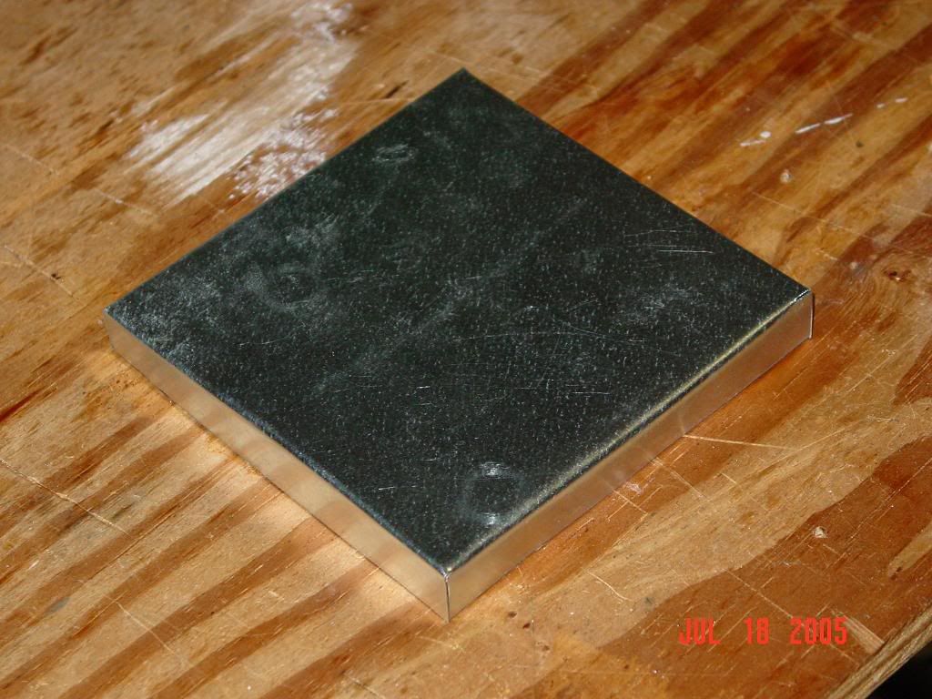
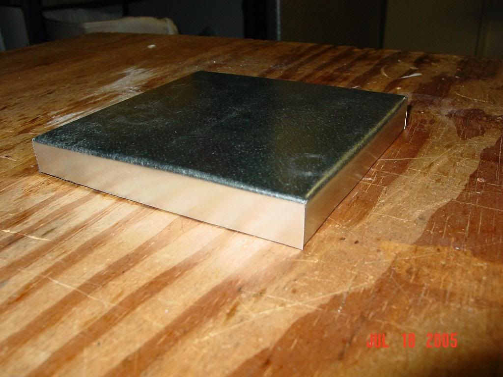
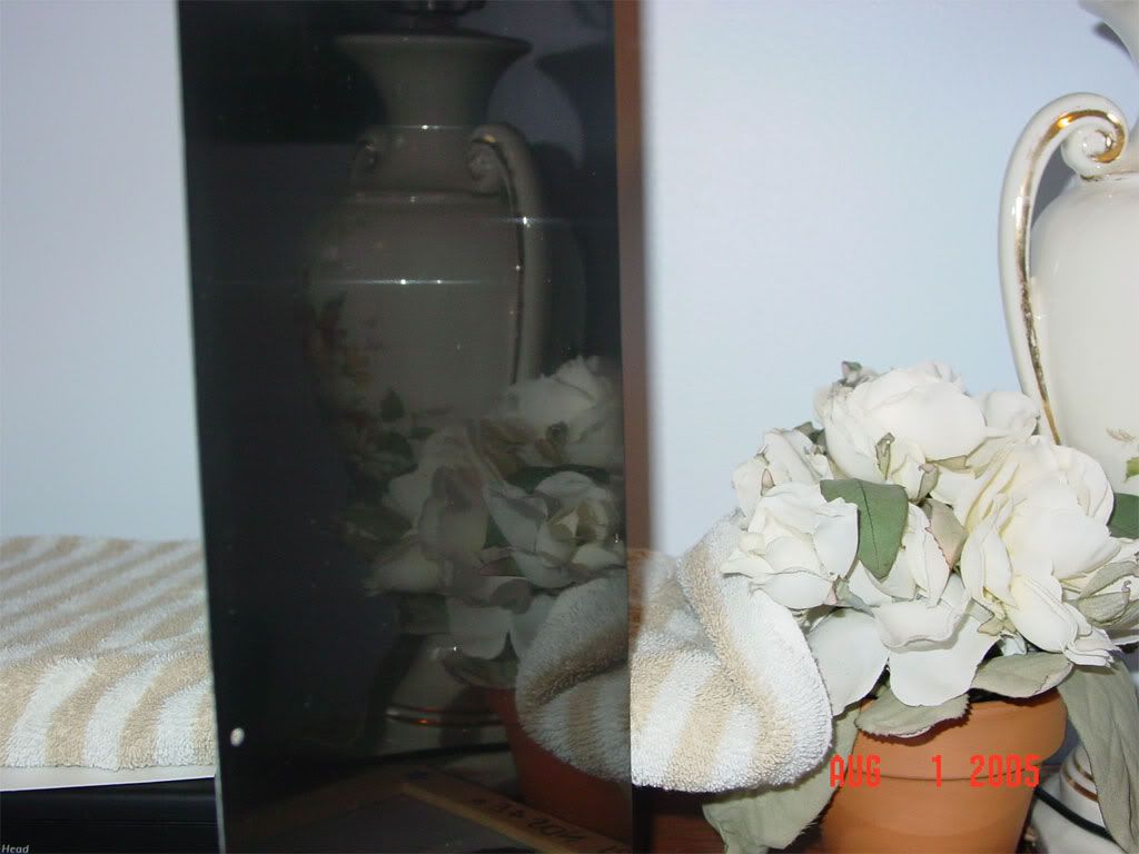
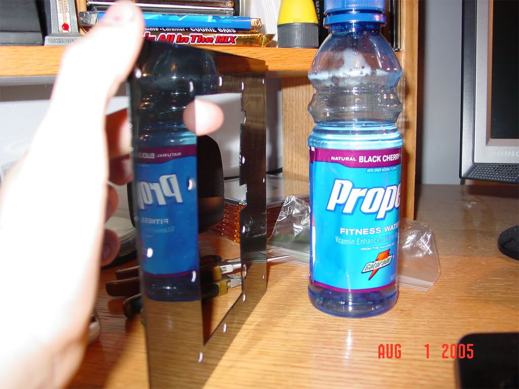
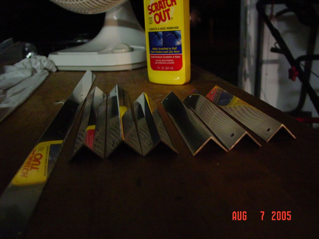
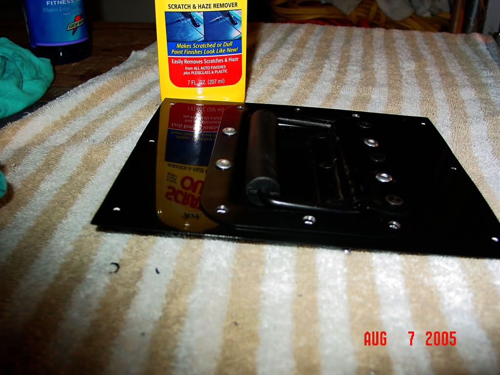
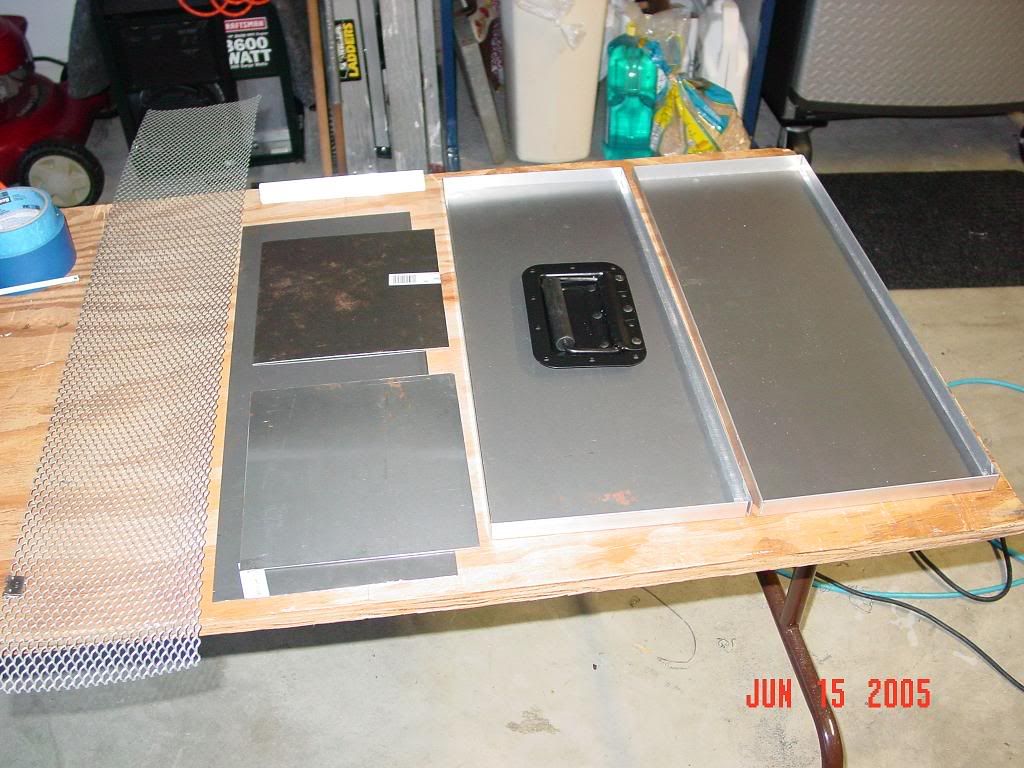
Some of the materials that will be used to make the box
DSC01336.jpg


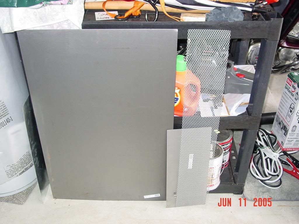
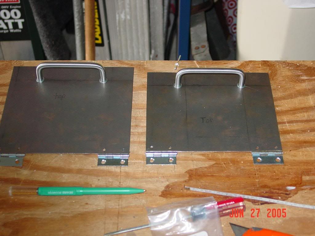
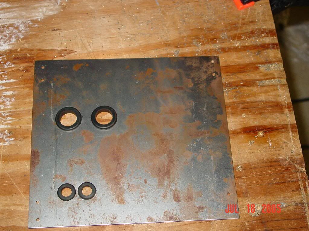
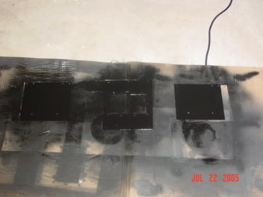
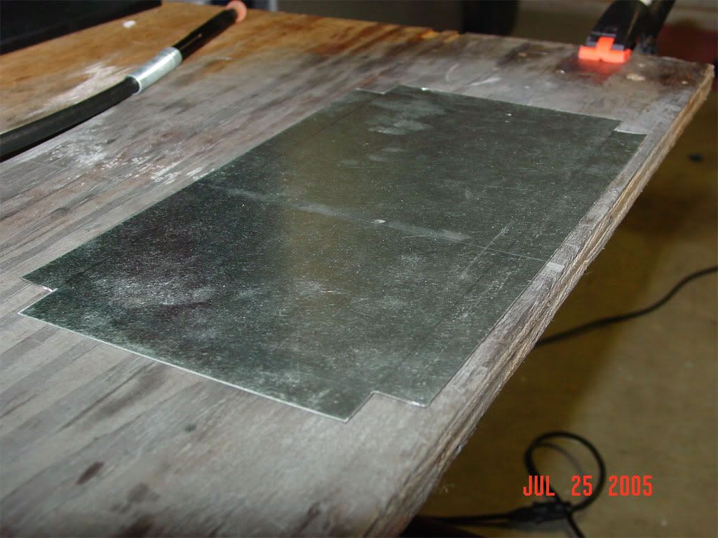
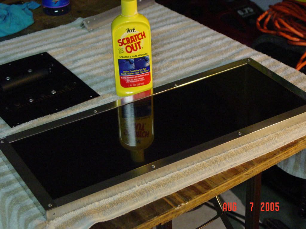
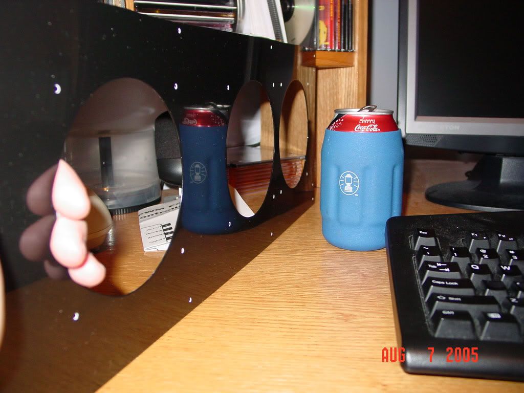
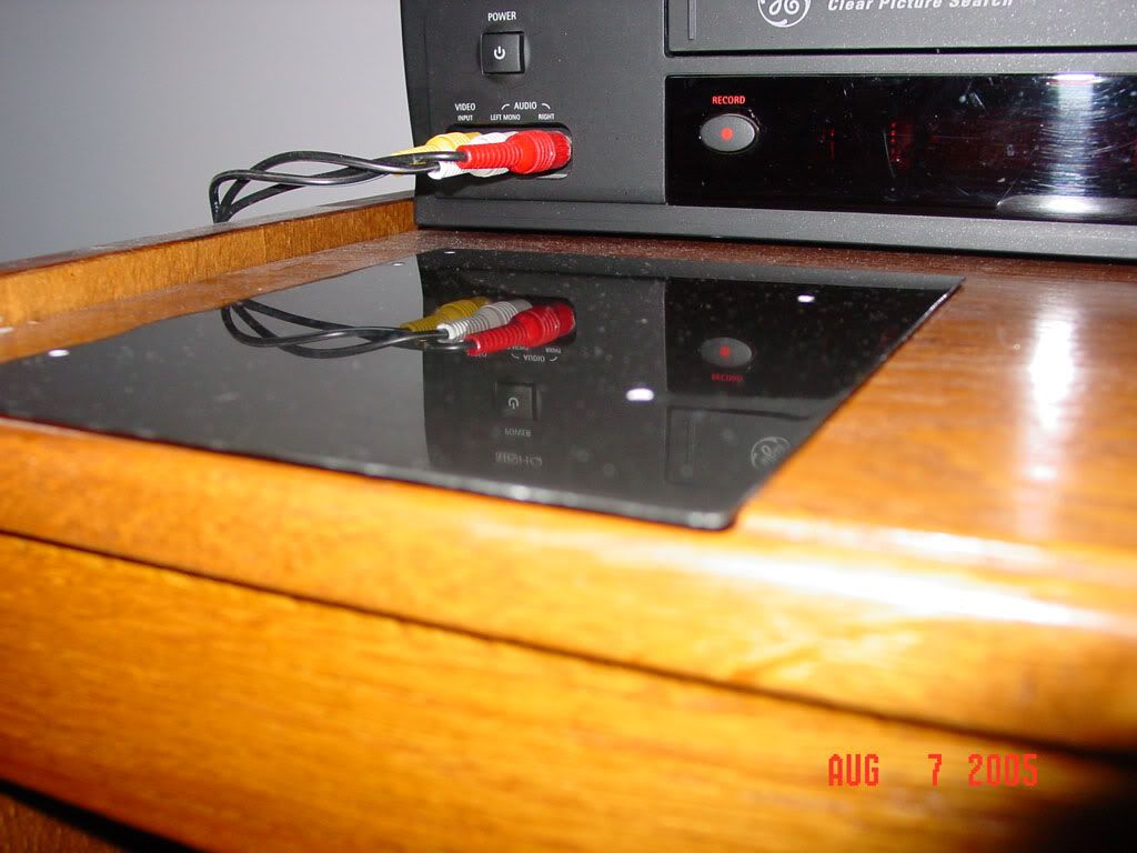
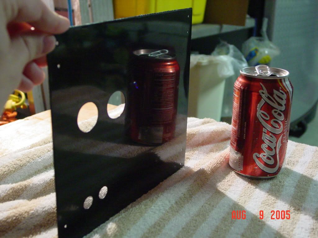
After I cut the sheets for the panels. I haven't sanded off the rust yet, but i'll do that before I begin to paint:
DSC01338.jpg


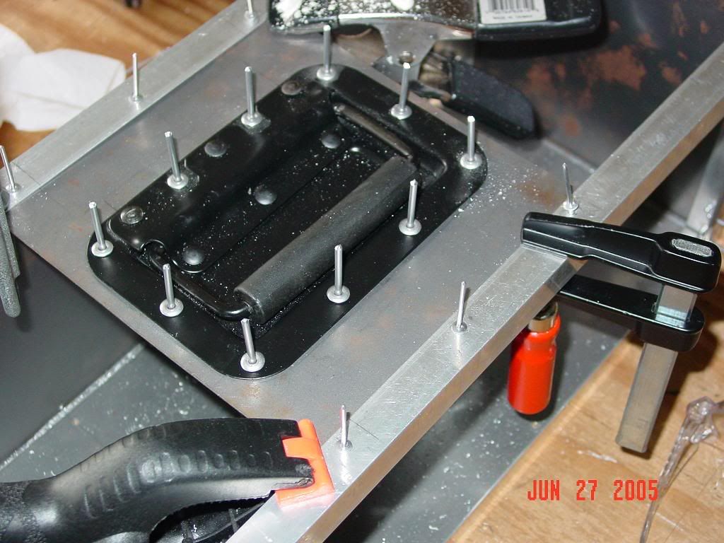
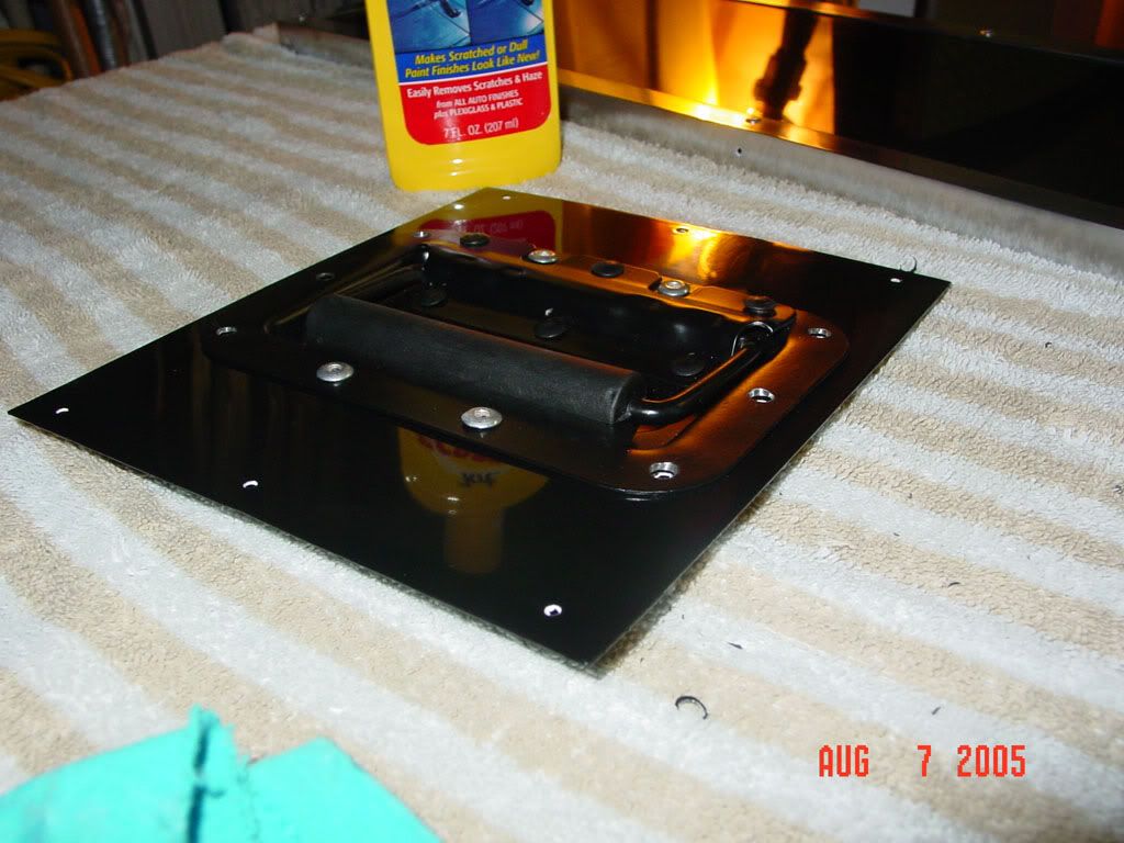
Closeup of the handle:
DSC01340.jpg


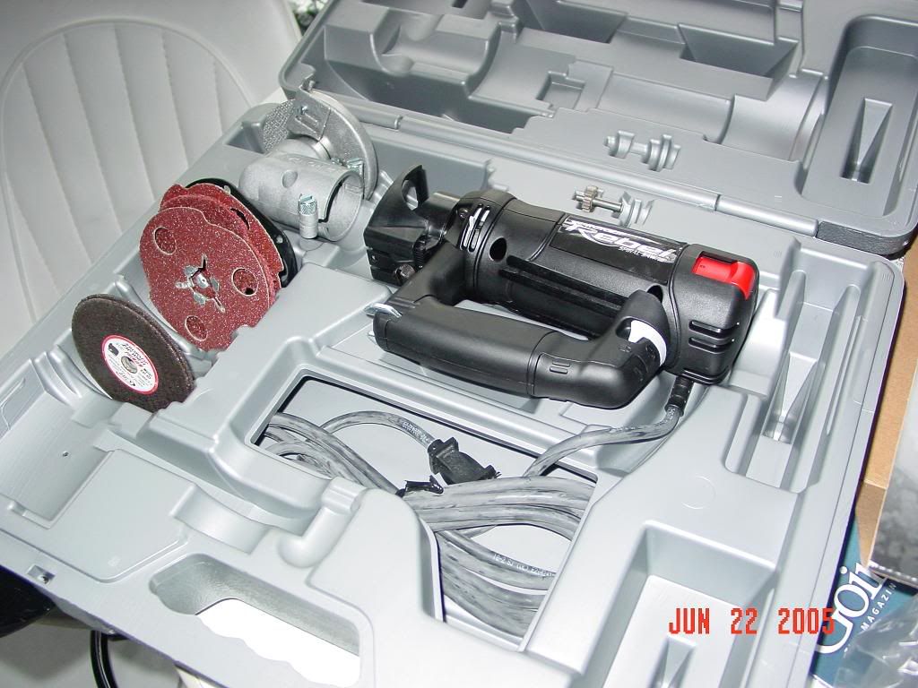
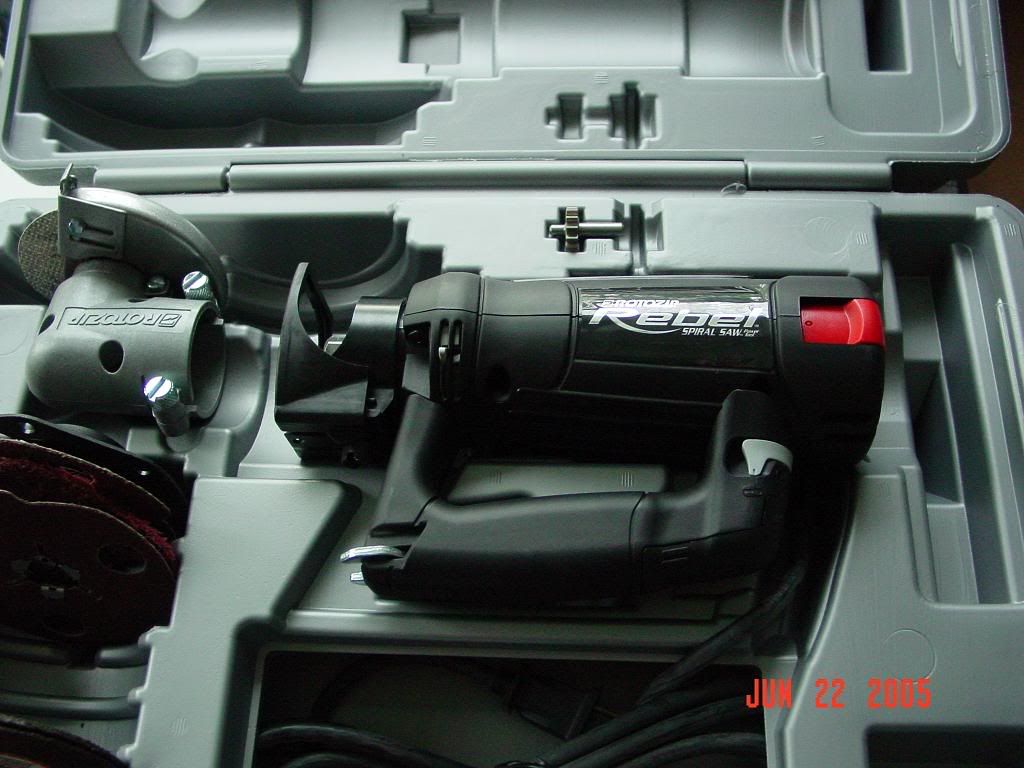
My next step is to double check that everything fits and is flush. This has been the most difficult thing for me, but that could be attributed to my lack of experience and metal cutting tools. But hey, a jigsaw and a rotating power tool (kinda like a dremel, but better) get the job done :).

After that, I will line everything up then drill holes for the rivets. I'll then sand the panels and angles until they are flat, apply primer, sand, pain - that whole deal. After that, I'll use rivets and/or screws and nuts to put together the box. Installation of components will follow.

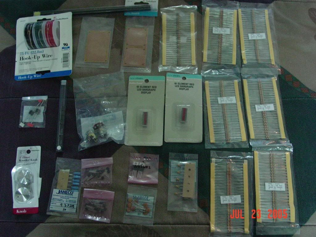
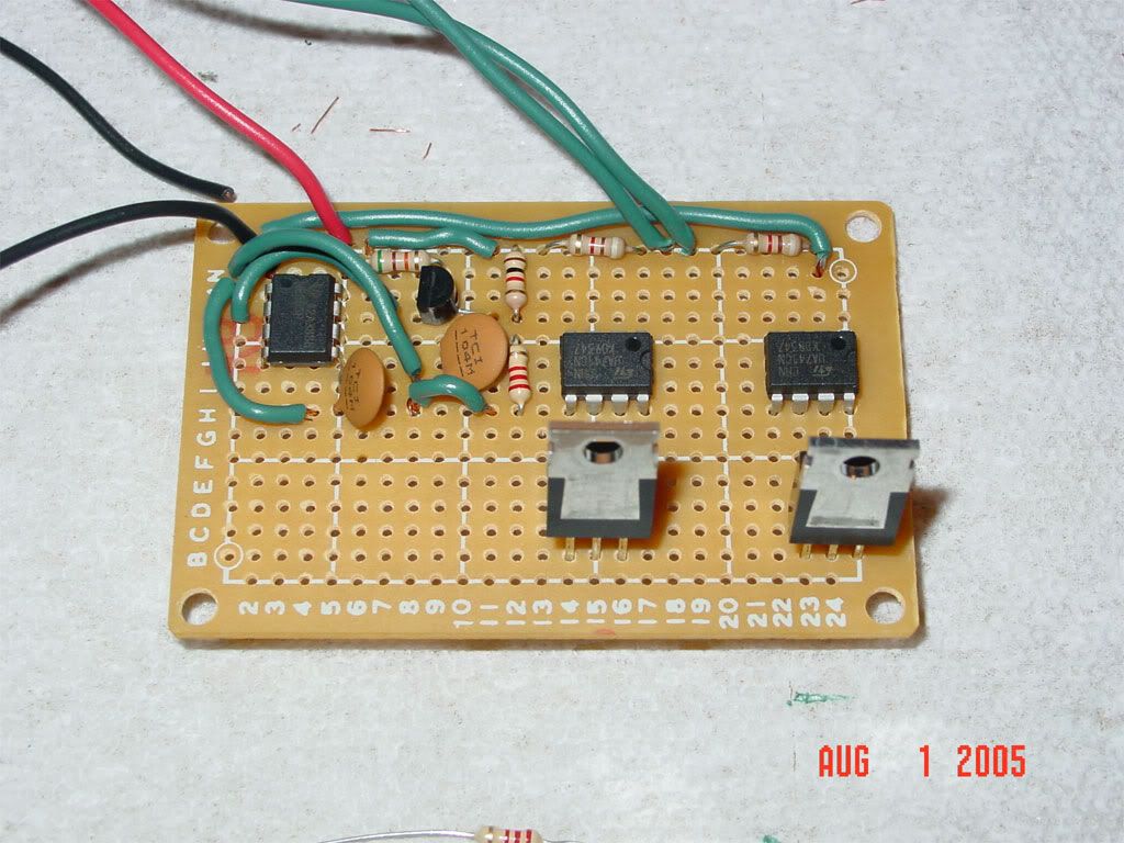
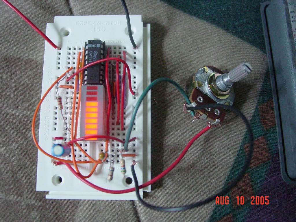
I still need to build a fan controller circuit, but it isn't absolutely necessary, so I'll probably do this after everything is up and running.

So, what do you guys think? Suggestions and comments are welcome.
 
Today I'm lapping my athon 64 adapter. It had scratches on it when it arrived...and I am really anal so hopefully I can clear them up.

Quick question: Do you guys think I should run the radiators (and only the radiators) in parallel or series? I have the wyes to connect them in parallel, and it isn't much of a problem other than it could be tricky with tubing - which is why I will be using coolsleeves.

Anyway, if I make sure that the flow is equal between the radiators by means of pinching tubing on the less restrictive one, will it offer a performance benefit? I am honestly not sure how restrictive the rads are. Heck, I am using 1/2'' ID quick disconnects by colder that allow only 3/8 nominal flow...so should I even bother? On the other hand, most blocks are probably more restrictive than the colder disconnects.
 
Looks cool but from now on i would use imageshack or photobucket coz that one sucks.
 
Majin said:
Thats looking nice.
Keep going I want more!

Thanks, I'm working hard on it :). It is taking me longer than expected because not only have I been busy with summer courses and work, but this is my first big modding project (I don't consider my previous w/c projects to be nearly as big).

Anyway, hopefully I can start drilling so I can paint.

Oh, I am kinda stuck on what I want to make it a little more decorative. I have 3 120 mm fan grills (plain chrome, but hey, I got them all for 2.89 shipped off ebay :)) so that will add some decoration to one side. The other side will have that mesh as seen above. What about the front? I was thinking of putting my fan controller on the front. I plan on making it two channels, one channel to control the fans on the first radiator, and the other to control the fan on the smaller one. I also might put some of those bar LEDs to indicate the voltage level or something.

I've considered a VFD, but I know next to nothing about them and they are kinda expensive...

Oh, should I polish the angled aluminum and leave it that color, or paint it black like the sides? What about the mesh?

So yeah, suggestions are definetly welcome.
 
Well, I got a rotozip as a gift earlier today :). It was a really early birthday present.

Here are some pics:

Everything held together with clamps
DSC01344.jpg

DSC01343.jpg


My new tool :)
DSC01345.jpg

DSC01346.jpg
 
altec said:
That well work as good if not better then a hole saw.

Excellent. I got the one with both the spiral saw and zipmate attachment. I'll get the circle attachment soon (the more expensive but better one).

Question: will the sabrecut bits work on steel sheets? The manual says they work on aluminum, but makes no mention of steel sheets.
 
DarkenReaper57 said:
Question: will the sabrecut bits work on steel sheets? The manual says they work on aluminum, but makes no mention of steel sheets.

Alu is a harder metal to cut then steel but just to be safe i would try it on some old sheet metal or something.
 
altec said:
Alu is a harder metal to cut then steel but just to be safe i would try it on some old sheet metal or something.

Really? I thought steel was harder to cut than aluminum since it is sturdier. I guess these properties have nothing in common?
 
altec said:
Alu is a harder metal to cut then steel but just to be safe i would try it on some old sheet metal or something.

Aluminum is not harder to cut than steel. just have to use a slower speed to avoid heat marks and stuff.
 
Troney1169 said:
Aluminum is not harder to cut than steel. just have to use a slower speed to avoid heat marks and stuff.

Go cut some sheet Aluminum then try to cut a sheet of steel. Just coz Aluminum is lighter does not mean its not easyer to cut. Aluminum is just odd like that. Thats why i hate working with it.

Edit,

I'm not just saying with a hole saw anything cutoff wheel, Plasma cutter (I love that thing), routing bits, ETC.
 
Well, I made some progress today. I changed the design of the top a abit - originally I was going to have a uniform panel with a hole cut in the center so I could mount the handle to it. The side mesh is going to be hinged so that is how I was going to be able to check for maintenance/leaks/whatever.

Suffice to say, that would leave very little space for workroom, and my vision would be somewhat limited.

I decided to divide the top into thirds, having the center part with the handle attached directly and unmovable. The other two panels will be hinged and the unit will open up like a cardboard box, so to speak.

Oh guys, let me know what you prefer - the thumbnail with link to larger pic, or the entire larger pic. I don't really want to resize to be honest...it is a royal pita in my mind.

Here are a some update pics:

Notice the hinges lying roughly in their places - I will mount them inside the frame
DSC01348.jpg


DSC01347.jpg


Here are the panels that will open up. I may buy a couple small stationary handles at home depot or something and mount those so there is something to grab when lifting them.
DSC01349.jpg


As you can see, I have most of the rivets in place, but not riveted yet. This is mostly for drilling purposes - they hold everything together and make sure all of the holes line up.

My intention is to finish cutting/drilling most of the thing, then take it apart again (keeping track of what goes where), make some final cuts, then start sanding painting. I intend on getting a nice glossy (or hopefully mirror-like) finish on the panels and frame.

Is this the best way to go about things? My main worry is that I'll forget to make a certain cut or something, and when I go to make that cut, it will mess up my paint job. Even careful planning isn't foolproof :rolleyes: .

Hopefully the rotozip will work with that sheet steel to make a nice cut (with a circle cutting attachment). Unfortunately, I don't have the attachment yet, so I can't try and see. I don't wanna drop money on the circle cutter and find out it doesn't work properly. I'll probably just freehand some scrap to get the feel of it, as I have never used the tool before, and judge from there.
 
Well, this will be the last update for a while. I am going on vacation to Minnesota for a couple weeks to visit family and attend a sister's wedding.

Anyway, I bought a couple cool handles for the flip-up panels on the top. Here is a picture of them mounted to the panels:

DSC01356.jpg


Here is a picture of the carrying handle with rivet heads in to check for alignment.
DSC01357.jpg


I placed some of the w/c gear into the box to make sure things fit properly. The components aren't in exactly in place, but you get an idea. Here are a few pics:

DSC01361.jpg


DSC01358.jpg


DSC01359.jpg


The duct tape on the corners is just to hold things in place - it will be gone once I paint and rivet everything together.

The next step when I get back will be to mark and cut the 120mm holes for the side, and smaller ones in the back for the grommets (for tubing and power).

I'll probably have my LCD temperature display by then, and hopefully my fan controller circuit. I'll make the appropriate cuts so those will fit on the front.

After that, it is finally time to sand and paint!

I have considered etching some plexi and adding it to the front/sides to add some bling to the box. What do you guys think? What about plexi-cut letters (non-etched, but actual cut out letters) that spell something like "Liquid Cooled"? I cou
 
Well, I'm back from Minnesota now so I can start working on my project again. I found some stuff at good prices at a surplus store there - heatshrink and 3 150 x 172mm past fans. I tested the 24V DC fans at 12V and wow..do they push a lot of air. They are rather noisy at 12V, though. They turn on at 5, but don't push a lot and barely move. At 7 they are almost silent and push quite a bit of air...more than 120's at 12V.

I gave my Panaflo U1A's a try again for comparison, too. At 12V, both the U1A's and papst fans are rather loud, and I would not run them at that. At 7V, the papst fans are quieter and push more air - the U1A's tend to have a bit of a ticking noise...perhaps this this just by design of the motor? It isn't too noticable, though.

Anyway, here is the dilemma. I plan on shrouding the radiators since they are not flush at the intake of the box. This way, there is good airflow through the fins. I already have 1 shroud for the bonnie core to fit the 120mm fans, but I need to make a smaller one for the chevette core.

If I use the papst fans, I will need to make new shrouds. Heck, I might not have room for shrouds in the box, as these papst fans are 51mm thick. I was only planning on having shrouds of 2 cm height or so, due to space contraints. I will also need to get another hole saw (or return the other 4 1/2'') for a 5 or 5.5''.

I also don't be able to use the 120mm fan grills (they are just basic silver ones) on the larger fans.

Is it worth it? Should I use the papst fans?
 
Well, here is a small update. I decided to stick with the panaflo U1A's after all. It was just easier to work with them, and the papst fans didn't quite fit right.

Anyway, I used my holesaw to cut some holes in the side. Here is the result after I deburred with dremel, sanded, drilled some holes, and put on the grills. I haven't painted it yet - I only did this for placement.

DSC01606.jpg


DSC01607.jpg


I also started making the shrouds. I think I'm actually going to make a second for the bonnie core after all. The older plexi shroud will need to be modified and won't look as good.

Here are a couple pics. I still need to drill the holes, seal the sides with solder, and level the edges a bit. It is hard to make everything flush when using only a mallot and an edge to make short bends. Well, it was for me at least.

DSC01614.jpg


DSC01615.jpg


Here is the back plate of the unit - it is a bit rusty now, but soon it will have a nice glossy black finish like the rest of the unit :). I made the circular cuts for the grommets. The water tubes will go into the larger ones. AC power for the pump from an outlet will go through one of the smaller ones, and DC power from my computer's PSU will go through the other. It might have been better to integrate some sort of PSU into the external unit itself, but I opted not to due to space, weight, and having a PSU in such a close proximity to water.

I might add a hole for an on/off switch for the pump, but it might be a bit unsafe since it could accidentally be shut off...and bye bye system.

DSC01608.jpg


My next step is to get the electronic components for my fan controller so I can make the necessary cuts on the front. In the meantime I'll probably start sanding/painting.
 
I did a lot today, even though I don't have a ton to post. Painting is very time consuming, lol.
Anyway, I took a pic of the shroud after finished and primed. It only needs a couple coats of the glossy black paint, and it will be done.

DSCF0002.jpg


I'll post some pics after the painting is finished. Hopefully I'll get some more replies once everything starts to come together.
 
im a cad guy myself.. nice design by the way..
looks like mech desktop to me though..
i think you should try autodesk inventor.. if you have a chance..
pretty easy to use.. .
looking good.....good luck..
 
Crazystick said:
im a cad guy myself.. nice design by the way..
looks like mech desktop to me though..
i think you should try autodesk inventor.. if you have a chance..
pretty easy to use.. .
looking good.....good luck..

Autodesk inventor...hnmmm, never heard of it. The only reason I used autocad for the design is because I'm an engineering major and I wanted to get more experience using it. They didn't teach us enough in the preliminary courses imho.

What are the advantages of autodesk inventor?
 
I'm in the process of painting the panels now. No pictures yet - I haven't applied much color coat yet. Spending a good amount of time priming and sanding is key to a nice finish :).

Anyway, I have 2 options for the support frame made of angled aluminum - I can give it a mirror black finish like the panels, or I can sand it to hell and keep it aluminum colored but give it a mirror finish that way.

What do you guys think would look better - I cannot decide. The chrome-ish look might conflict a bit with my black thermaltake tsunami case, but it will add variety to the external unit.

I'll probably sand one support beam down to a mirror finish and see how it looks, post a picture, then decide. I'll take any responses into consideration, of course :)
 
DarkenReaper57 said:
Autodesk inventor...hnmmm, never heard of it. The only reason I used autocad for the design is because I'm an engineering major and I wanted to get more experience using it. They didn't teach us enough in the preliminary courses imho.

What are the advantages of autodesk inventor?

Well inventor is another Software. It is Parametric Modeling program , with feature - based parametric modeling. You can create part(s) and later combine them to create assemblies. It seems to run almost identical to Mechanical Desktop, if youve ever come across that software. I wish to get to use sold works.. Anyways, You create a an image on a 2d surface by creating or selecting planes, and you pretty much work off of that to then create and extrude your 3d image(s)
Inventor was another companies' software until autodesk bought them out and labeled it for their own use. Its pretty much autodesk's answer to solidworks @ a cheaper price. But Your project seems to be coming along
good luck!
 
Well, I sanded and polished one beam to a mirror finish to see what it looks like. Here are a couple pictures:

DSC01625.jpg


DSC01626.jpg


I'm seriously thinking of just keeping them unpainted. Not only will it be less of a hassle, but it will add some variety and contrast to the unit.

The panels will still be black w/a mirror finish (if all goes well) of course.

What do you guys think?
 
Well, I went through tonight and resized all of my pictures to 1024 x 768. I also found better hosting (photobucket) so now it is less of a hassle for those who view the log.

Here is a picture of the shroud with a couple coats of black paint. I haven't sanded it yet, and I might not. It will hardly be seen, anyway.

DSC01634.jpg
 
Well, I got all of my electronic components today. I was surprised to get it so quickly, as I ordered it wednesday night. Jameco is a very good company :).

DSC01636.jpg


Quick question for all of you electronics gurus out there, though. I haven't gotten a much of a response from my thread in the electronics forum :(. Anyway, how would I change the VLo and VHi signals on the LM3914 chip to 4V and 8V, as said here http://casemods.pointofnoreturn.org/pwm/circuit3.html ? I want to integreate the voltage monitoring circuit in his other guide there (there is a link on that page).

Thanks for any help.
 
It has been a while since I have updated. Most of my time has been spent painting/sanding. Unfortunately, it is taking longer than expected, mostly due to my inexperience and repeated sanding into primer on the color coat :(.

I have, however, finished 2 panels. One is for the bottom, and the other is the panel that has a cutout for the large black recessed handle.

I don't know whether or not I want to add a clearcoat. These pieces below have been sanded to 2000 grit, then polished a with a scratch remover. A clearcoat might add some durability, but I don't wanna screw up my hard work...I guess I'll see. I can always test on the inside of the bottom piece, since it will not be seen too much anyway.

Some pics of the painting process. The paint is not yet dry in most of them.

DSC01628.jpg

DSC01629.jpg

DSC01630.jpg


Aftermath :p

DSC01698.jpg

DSC01701.jpg


I also made progress on my larger shroud. Here is a pic before I bent the edges, but cut it out
DSC01638.jpg


After bent, soldered, and all holes drilled
DSC01691.jpg

DSC01690.jpg


I'm priming it now, so it should be done within the next day or so.

I started building the 555/741 circuit. Now, electronics are completely new to me, so it isn't exactly pretty. I just hope it works when I am done...

DSC01702.jpg


Red and black are +12V and ground, respectively. The green longer wires go to the 10k pots (I will split each wire).

So yeah, hopefully I'll finish painting soon. I only have 2 weeks or so left before I move back to school, so I really want to finish...
 
Update time.

4 panels have been finished, but 3 still remain. One of them I have not begun to paint (the front) because I still need to make the cuts to put the LED's, etc. I really want to finish my circuit first, too...

Anyway, I've been sanding and polishing to no end mostly. I finished sanding/polishing all of the frame (at least the parts that will be seen.

Not perfect, but fairly reflective.
DSC01732.jpg


I began to assemble the bottom, and riveted some things into place. Here are the results (it is actually flipped to see the mirror finish on the bottom).

DSC01718.jpg

DSC01724.jpg


Started riveting the large handle into place. I need some longer rivets to go through some support beams, so I'll pick those up tomorrow.

DSC01726.jpg

DSC01727.jpg


And the exhaust panel - it has some dust on it since it sat a day.

DSC01716.jpg


One of the top flip-up panels. It too has dust...but oh well, you get the idea :)

DSC01708.jpg


Tomorrow I'll paint the radiators if I have time. I'm off the next few days so I'll have extra time to work (and hopefully make some big progress before the 18th-ish).
 
Somehow I have a feeling that this is going to look friggin sweet and cool well to boot. Anyone want to bet against me? :p
 
ikellensbro said:
Somehow I have a feeling that this is going to look friggin sweet and cool well to boot. Anyone want to bet against me? :p

Heh, thanks. I hope it turns out well after all of the hours I've put into it.
 
Damn! Thats some [H]ard|modding right there. Sweet work man. I love that gloss on everything.
 
Small update.

Finished 2 more panels today - w00t!. There is only one left, which is the front. Unfortunately I have not even primed it yet, because I still need to make some small cuts. I'll get started on that tomorrow.

2nd top flip up panel:
DSC01736.jpg

DSC01742.jpg


The back panel:
DSC01740.jpg


The exhaust panel with fans and grills installed:
DSC01744.jpg

DSC01746.jpg


I did goof on one thing though, and just now noticed. It seems I accidentally swapped the front and back panels a long time ago and mislabeled them. Thus, the one shown above was originally going to be the front.

Since I have not started on the front yet, I will probably just put the one shown above in the back. The problem is it does not fit (holes drilled for rivets do not line up). I can, however, just redrill the holes in the panels. It doesn't matter if the holes are doubled or whatever on just the panels, since they are not seen. It is just a bit of an annoyance and sets me back a bit, thats all.

I also need to be careful of the finish when redrilling, heh.
 
Well, I woke up today and was pissed. The two panels I finished last night had divets all over them from the towels laid over them to protect them from dust, etc. Ironic, eh?

Anyway, I sanded them down again and had to apply another color coat to the back panel. I didn't need to reapply any color to the top panel, but I'm going to try a few clearcoats on it. If I can get a nice glossy finish with the clearcoat, I may apply it to the other panels to protect them better.

If there are other ways to protect the panels that you guys can think of, though, please let me know :)

Anyway, I finished the prototype of my VRM on a breadboard today. I still need to modify it so VLO and VHI are 4V and 8V, respectively, instead of 0V and 12V.

DSC01751.jpg


The LED's really are red...the camera made them look orange for some reason.

Here are some pics with the radiators and shrouds in place - I wanted to make sure everything fit fine. At least one thing worked out for me today. It seems as though all of the measuring and remeasuring paid off as I didn't need to struggle to get the threaded rods though all of them.

DSC01757.jpg

DSC01756.jpg


Hopefully there is sufficient room in the front for the electronics now that I accidentally swapped the panels. I did some thinking, and it actually looks better with the exhaust on the right. It make sense to have the mesh on the left...iut is like a window as you can see all of the internal components. It will match the windows on my case.

Oh yeah, I still need to repaint the heater cores :). They are already prepped with painter's tape on the barbs as you can see.
 
Looking good DarkenReaper57! :cool:

What did you bend your plates with?

My project will have to wait for painting until some testing is done.
:)
 
Dunno said:
Looking good DarkenReaper57! :cool:

What did you bend your plates with?

My project will have to wait for painting until some testing is done.
:)

Well, I didn't actually bend the panels at all. I cut them with a sabresaw and metal sawbit.

I did, however, bend the metal used for the shrouds. I did this by simply clamping down the metal on a straight surface (wood in my case). I put the edge I want to bend against the wood and used a rubber mallot to tap along the part I want to bend to get a "soft bend".

It isn't perfect, as there are some minor inperfections on my shrouds, but it works when you don't have the proper equipment :).
 
If you need some help on figuring out that voltage display PM me and I will help you all I can. To start you need Rlo to equal your minimum voltage (most times it is grounded) and Rhi can be had by using the internal LM317 voltage regulator or hooking it into the maximum supply voltage (normally 12V for computer fanbus applications).

Looks like you ordered a whole bunch of resistors, let me know what the max value of the resistors are and I will see about making some voltage deviders for you so you can input them into Rlo and Rhi (and hopefully minimize the amount of extra parts to order)
 
DarkenReaper57 said:
Well, I didn't actually bend the panels at all. I cut them with a sabresaw and metal sawbit.

I did, however, bend the metal used for the shrouds. I did this by simply clamping down the metal on a straight surface (wood in my case). I put the edge I want to bend against the wood and used a rubber mallot to tap along the part I want to bend to get a "soft bend".

It isn't perfect, as there are some minor inperfections on my shrouds, but it works when you don't have the proper equipment :).

Hmm... Cool!

Believe me; when you see the state that some in industrial benders are in, you wont think your imperfections are bad.
How thick is your plate? Dont think that will work on 1mm plate.
:)
 
Back
Top