• Some users have recently had their accounts hijacked. It seems that the now defunct EVGA forums might have compromised your password there and seems many are using the same PW here. We would suggest you UPDATE YOUR PASSWORD and TURN ON 2FA for your account here to further secure it. None of the compromised accounts had 2FA turned on.
    Once you have enabled 2FA, your account will be updated soon to show a badge, letting other members know that you use 2FA to protect your account. This should be beneficial for everyone that uses FSFT.

DreamCatcher v2.0 “Worklog”

jedihobbit

Gawd
Joined
Nov 3, 2005
Messages
963
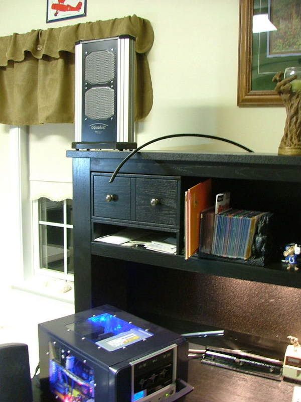
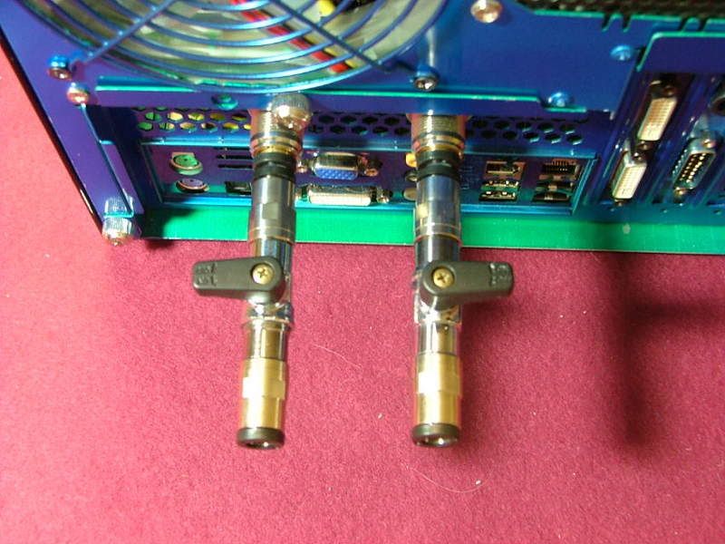
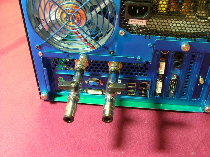
Now that Celtic Spirit is again being placed on indefinite hold, wanting to bring DreamCatcher into the realm of AM2, and seriously look at water-cooling, it looks like it is time to move on to v2.0. My initial W/C questions and issues will be presented in another thread (got to get that going!) as well as one following my testing & oc’ing the mobo assembly on air. As everything starts converging for “completion” those two threads will be merged with this one.

Here are the component changes that helped me to decide to call it v2.0:

Case: Convert MicroFly to MX6 “Hybrid”
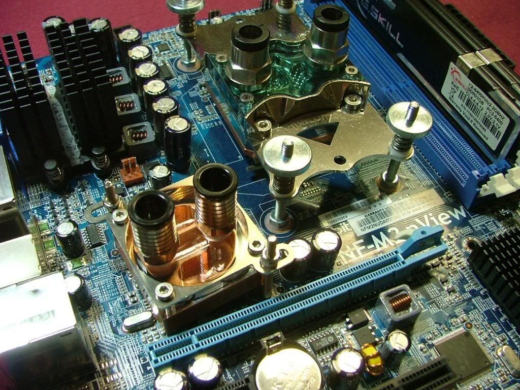
Mobo: Abit NF-M2 nView
CPU: AMD 4000+ Brisbane
HSF: Stock Opty 175 / Tt SmartFan2
Memory: Corsair CM2X1024 – 6400C4

These components were in the pipeline long before the idea of water-cooling came along therefore running the system on air influenced the original update.
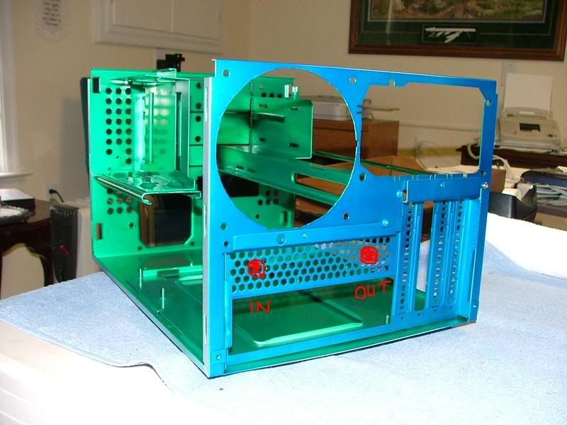
Case Conversion: While I love it, Ultra’s MicroFly case has a couple of “flaws”. One of which was airflow. Even though it uses a 120mm exhaust fan, intake is a little limited. The front of the chassis has a lot of holes and a 80mm fan, but the front bezel is somewhat restrictive for air intake. The MX6 was the next version of the chassis design and fixed that problem. The bezel uses a mesh surface that is very “breathable” and solved any restrictive airflow issues.

I had won a MX6 (through Steeeve’s SFF Store) and was about to sell it (pressure from boss lady) when I realized I could swap the exterior pieces to give DC better cooling – it just took a while to get around to doing that. Also as e-bay would have it I ended up with an nView, so last Sunday I started………
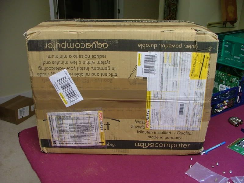
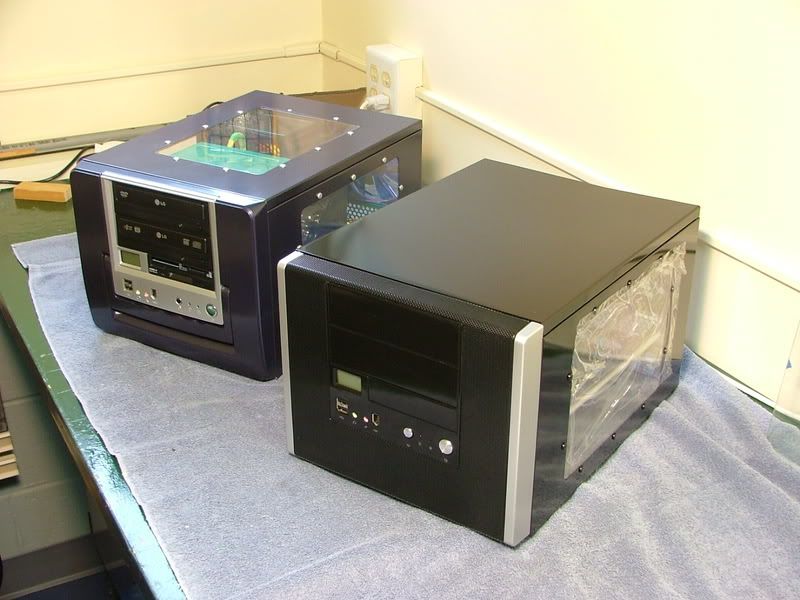
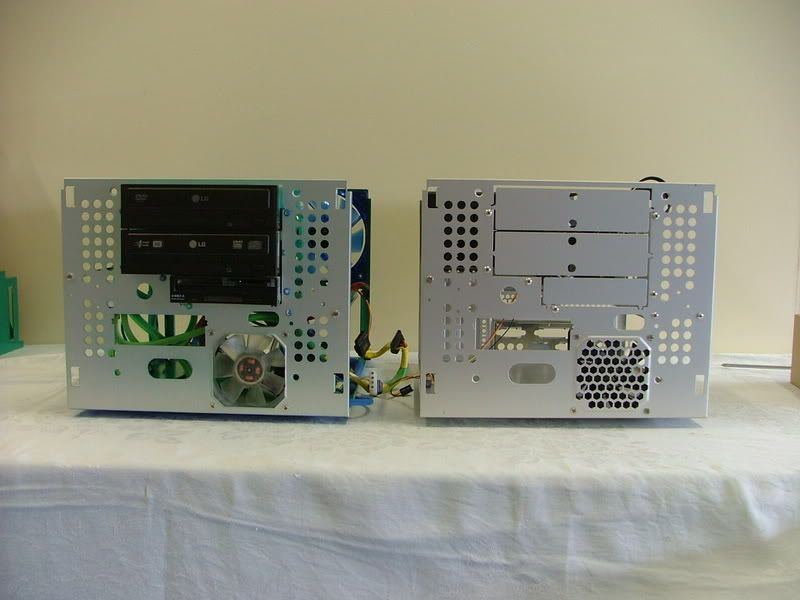
Here sit the two boxes waiting to be “hybridized” and then with everything removed but the bezels.

MFlyMX6.jpg
MFlytoMX6Switch1.jpg


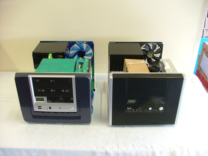
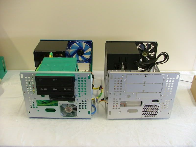
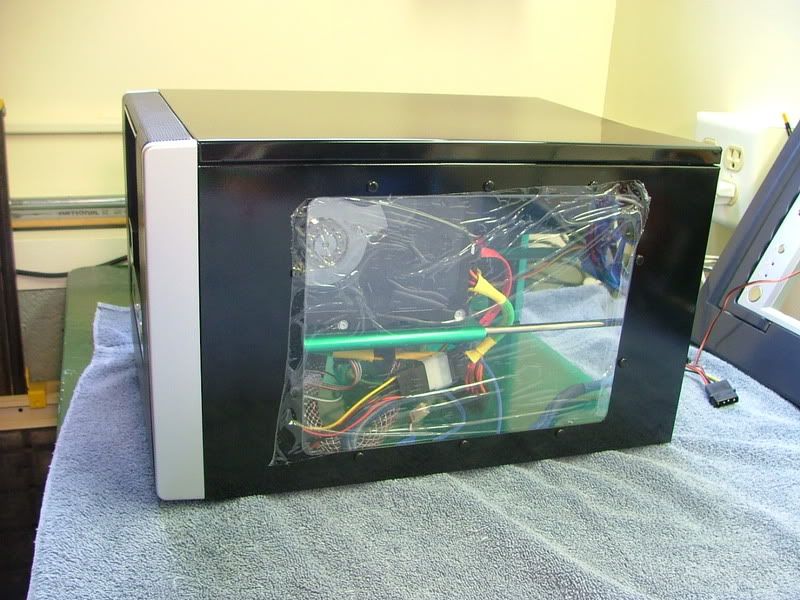
It was interesting to note that when I started taking the boxes apart Ultra opted to drop the four mounting screws used in the MicroFly and rely solely on the four retention clips with the MX6. Admittedly it makes life easier as one does not have to remove the HDD tray and the requirement for a short screwdriver if a PSU is in place. Here we have two views with the front bezel removed and finally a side view with everything together.

MFlytoMX6Switch2.jpg
MFltoMX6Switch3.jpg
DCv2asMX6.jpg


The left over chassis and exterior parts are headed for Yoda’s SMN, an attempt at a home server build (or excuse to build another computer!).

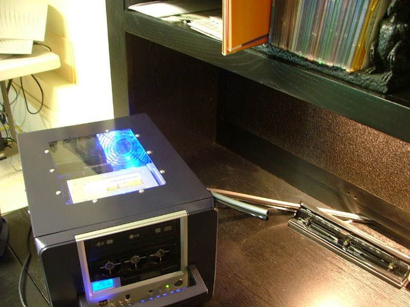
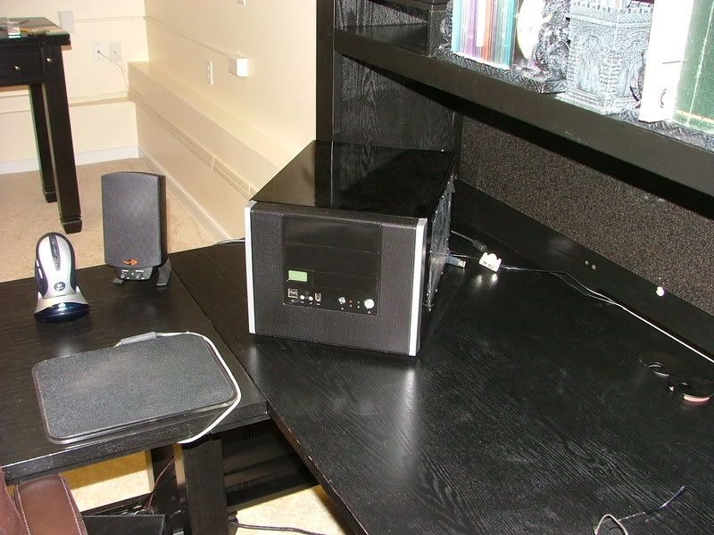
As one that does a lot of his stuff based on the “bling” factor, I’m going to miss the top window (may do one at a later date) but was compensated by the fact the new case matches my new office furniture the wife decided I needed! It is black with pewter knobs so
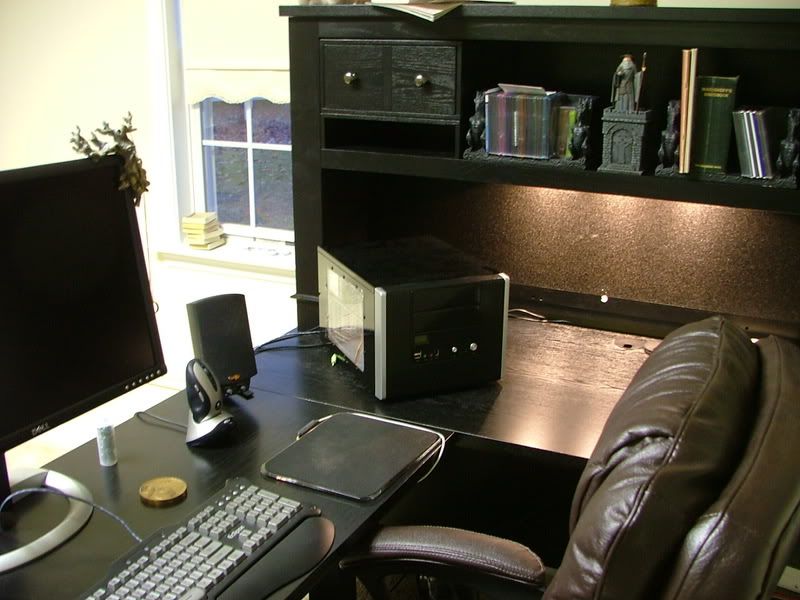
MX6-DeskMatch1.jpg
MX6-DeskMatch2.jpg


Sad isn’t it! :eek: :rolleyes: :D

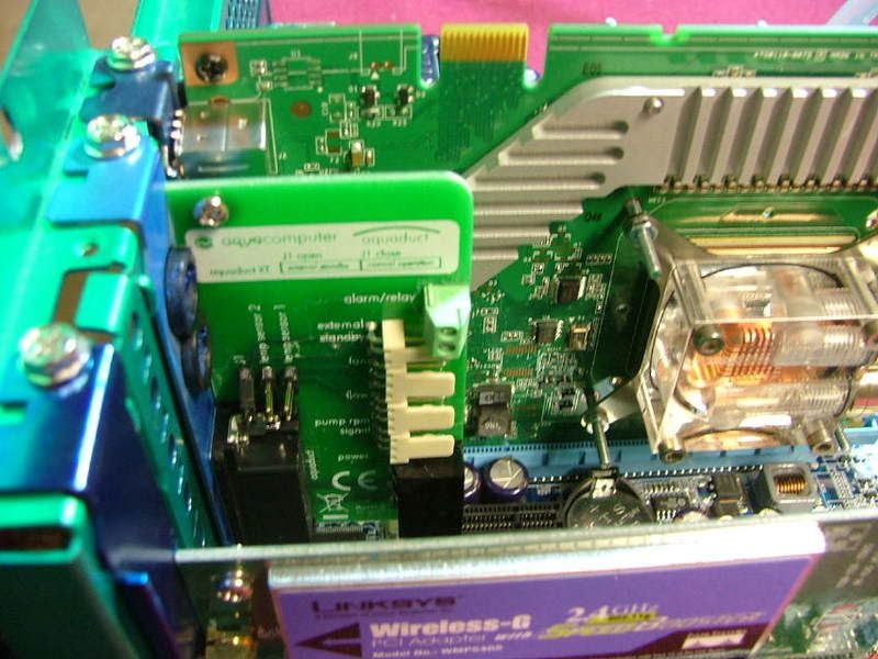
The rest of the stuff was the result of e-bay (what’s new) and a few “For Sale” threads here and there. Initially I was going to update DC by using Celtic Spirit’s Opty 175 and G. Skill PC-4000. Then it was decided to have a contest to see which would perform better Biostar / 175 or nView / 4000+ Brisbane. However after the frustration of reinventing the wheel (couldn’t get it through my thick skull 2 x 512 will always out perform 2 x 1024), ending up with an Opty 170, and running out of time it was decided I’d go with the theoretical oc’ing ability of the Brisbane. Also I decided to test the nView / 4000+ using the Tech Station for all kinds of altruistic reasons.

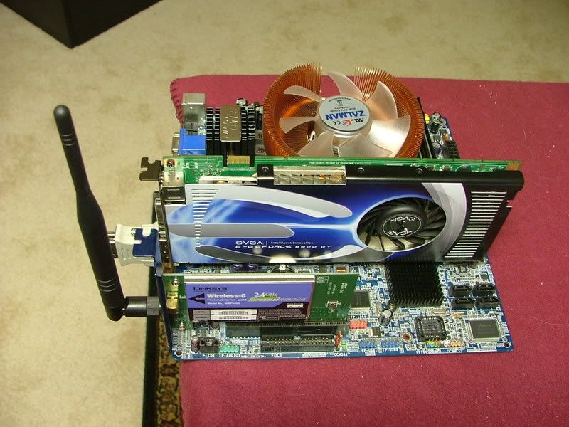
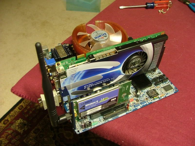
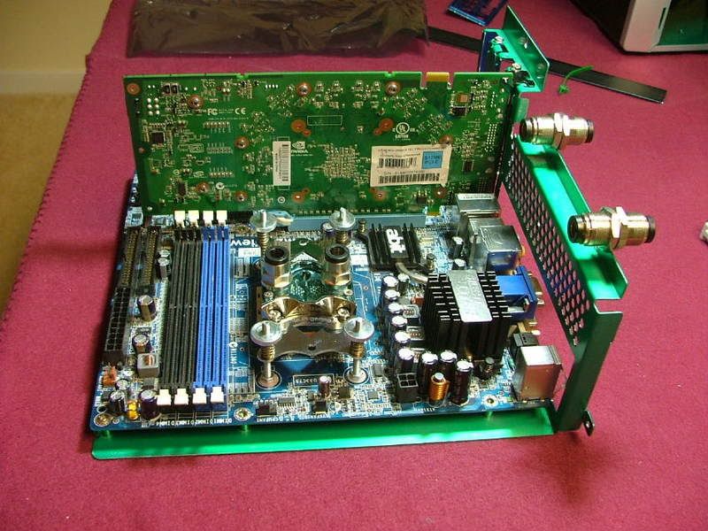
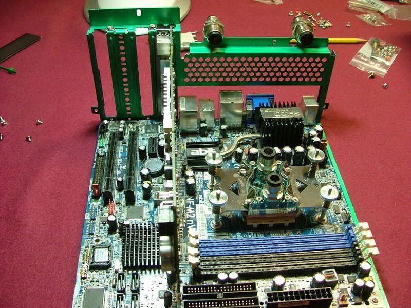
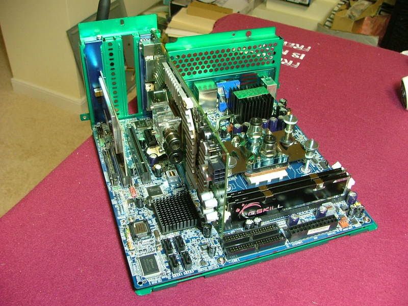
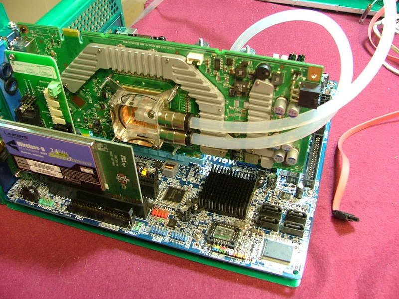
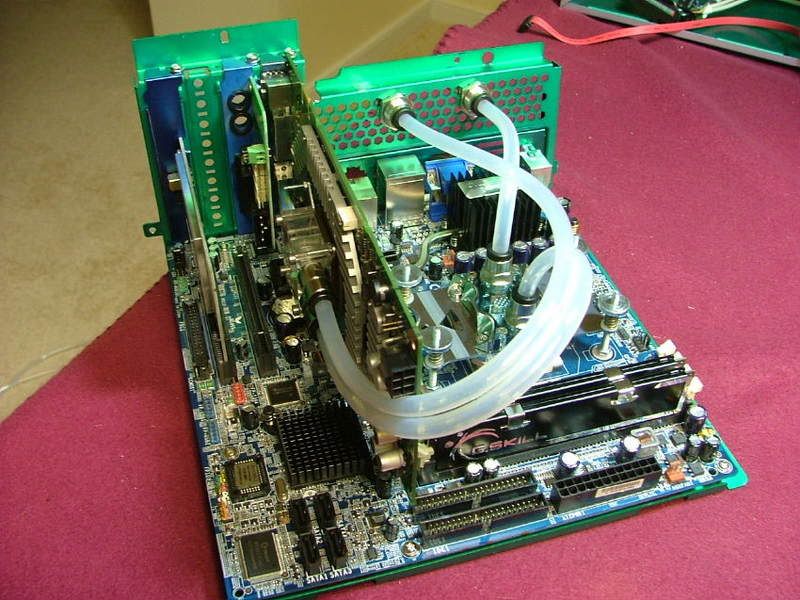
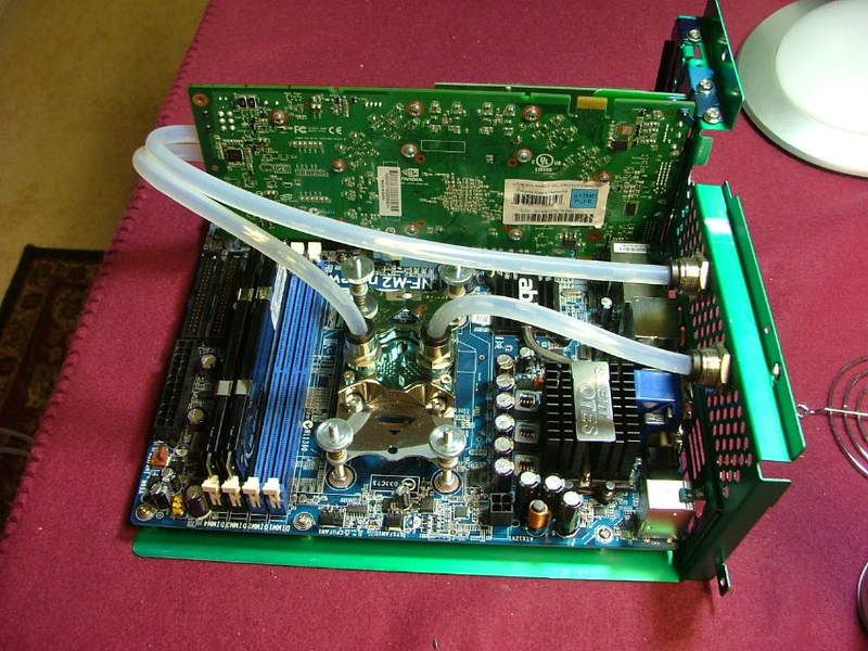
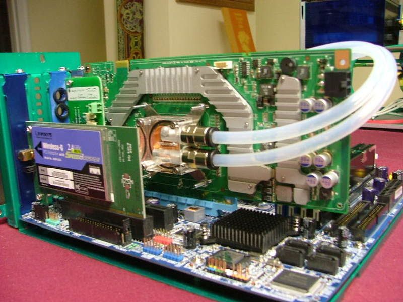
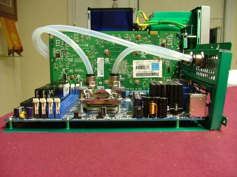
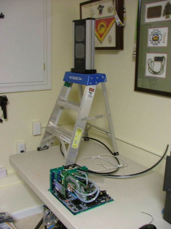
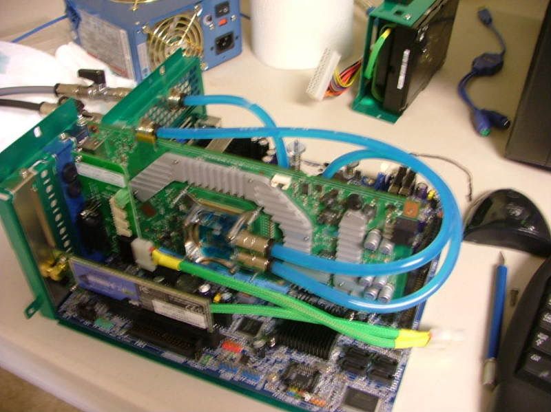
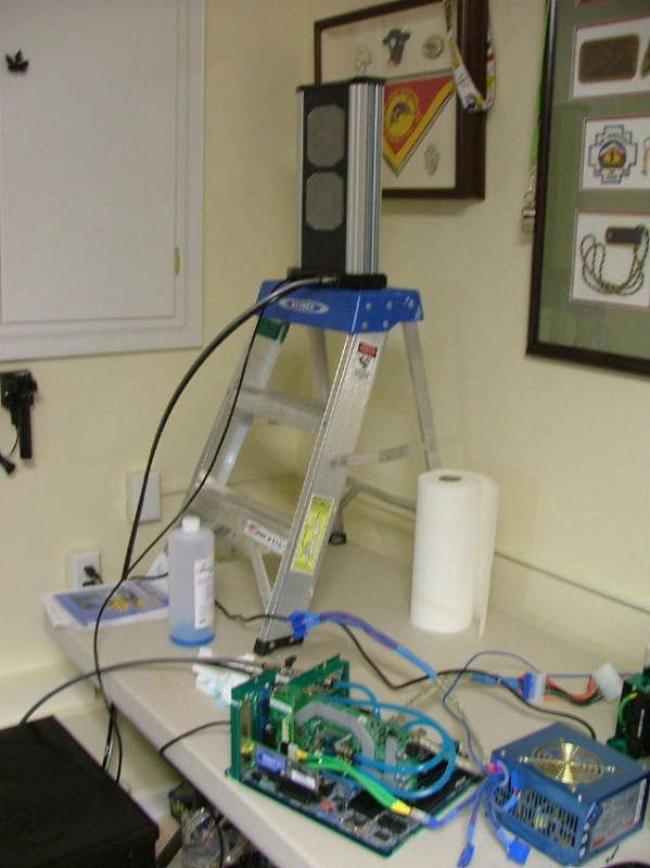
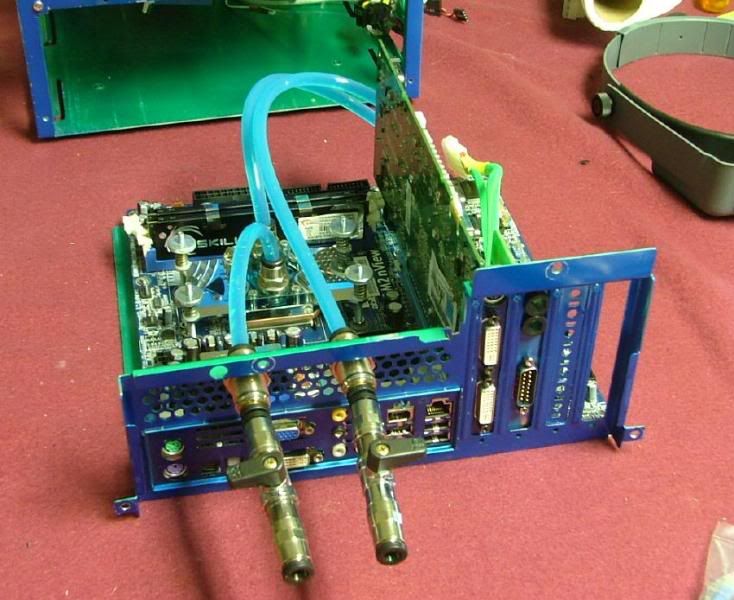
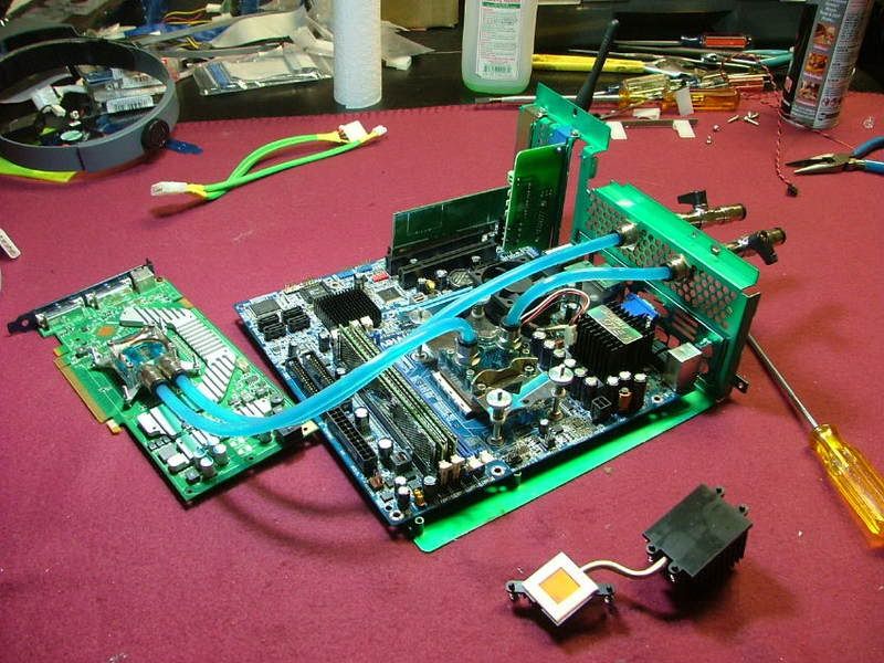
Besides swapping box parts last Sunday and Monday I threw the mobo assembly and the Tech Station together. With fingers crossed and my eyes shut I pushed the power button…..

Lft3-41stRunSM.jpg
nViewT-StaTop1stRunSM.jpg


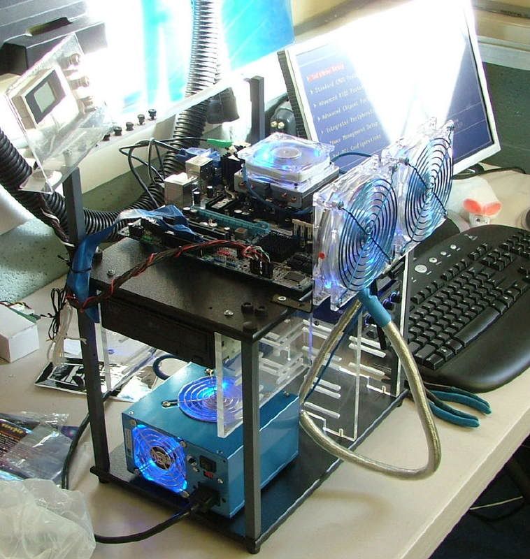
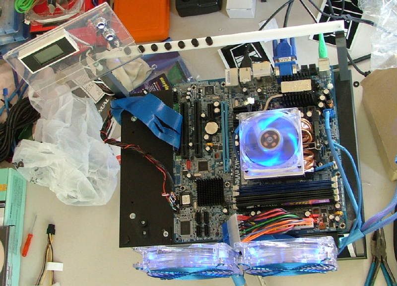
and was immediately reminded of two things:
1....the board was open box “You will need to reset you bios as the cpu has changed”
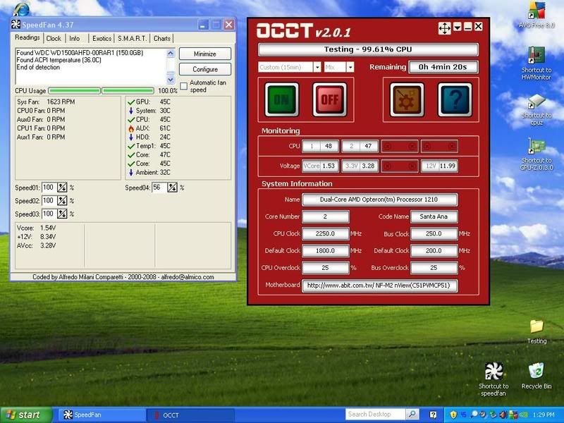
2....I need to flash the bios to correct the Brisbane temperature issues as I was showing 51 C for idle in the “Health Status Screen”

So now it is time to stop the physical assembly and begin the testing and oc’ing. As mentioned above I intend to do that as a separate thread and need to get started on that as time allows.

Chow for now!
 
Well it looks like everything has come to a screeching halt. As I was winding down my oc'ing decided to start setting up the evga 8800GT SC as there were some bios/driver issues concerning the cooler.

Long story short, the GPU is toast (begining the RMA process) and waiting on some pros to find out if the mobo is also smoked. :eek: :(:
 
Bringing this up to date in the fact that I got a replacement board and my evga RMA experience was marvelous!

This will be the first entry where the overclocking and water cooling parts of this project are now going to be part of the primary worklog.

For all intents and purposes the overclocking part (on air) is finished. After the water cooling has been installed and the system has gone through a “shakedown” period further oc’ing may be attempted.

So this is what the final settings are:

HTT: 291 for 3.06GHz
Vcore: 1.450v
Vdimm: 2.1v
Chipset Vcore: 1.24v
Hypertransport V: 1.22v

Rm temp is 22Cish, CPU 54C, Core 23C (per SpdFan)

This was backed up by a 12+ hour run of Prime.

While the setting didn’t run “stable” (long term prime or equal) did have on late night S & Gs session where I was able to run PCMarks ’05 and CrystalMarks at

HTT: 299 for 3.14GHz
Vcore: 1.500v
Vdimm: 2.1v
Chipset Vcore: 1.24v
Hypertransport V: 1.22v

PCMarks = 7436
CrystalMarks: ALU = 23308 / FPU = 25523 / MEM = 16397 with a TOTAL of 129348


Now here is the summery of the WC’ing thread and what’s happened!

In the end it was decided to go with aqua computer’s “plug & cool” fittings and not compression. It was felt that in the tight spaces of the mATX layout they would make installation easier.

In the final configuration it was decided to drop the NB and Mosfet coolers…..financial issues and the sinking dollar being the major considerations. It also didn’t help the NB cooler would be “hidden” under the PSU. As it turns out all major components are from Aqua Computer

Went for a combo 1 – 2 punch to cover rad, pump, res, etc….that will be handled by a Aquaduct 240 PRO Mark II . As I’m using AC’s plug & cool the tubing will be 6mm x 8mm with clear on the mobo and I believe black and gray (comes with the 240) from the 240 Pro.

Then for the CPU: cuplex XT di and then for the GPU: twinplex pro for FX8800 .

The cuplex XT di and a few fittings came from a state side e-tailer but the rest is coming from Berlin and shipping is ….. OUCH!

Anyway looking at the following loop: 240 >> CPU in >> CPU out >> GPU in >> GPU out >> 240

The following pictures are just things that I’m doing while waiting on the balance of the stuff to arrive.

Here we have the last views of the mobo assembly on air….

DCv2FinalAirSetup2.jpg
DCv2FinalAirSetup1.jpg


While unplugging the zalman CNPS8700 from the boards fan header I managed to smack my finger in the hsf as I pull…..lets just say the blades are sharp and anyone care to guess the blade spacing??

CNPS8700FinsRSharp.jpg
CNPS8700FinSpacing.jpg


Okay when I pulled the CPU cooler out of it box, I suddenly realized something – no mounting instructions! Hay, remember I’m a NOOB to this and a bit more paranoid than I probably should be. As it turns out my supplier from Germany has a great set of tutorials covering everything…..

http://www.aqua-computer-berlin.de/catalog/tutorials.php?osCsid=4j30suemja98u673ani7v4kml1

Stefan aka [MMM]slame has done them in both German and English!

Anyway I mounted the two straight fittings to the CPU block and then went to mount it to the mobo. One think I did notice (on the nView anyway) is the mounting holes are noticeably larger than the mounting bolts for the block. One of the disappointments that I had with this block was the finish on the base. Sadly my picture was fuzzy so I couldn’t use it, but it was discolored and had plenty of machine marks. After all of the shinny goodness on the top parts this was a bit of a let down.

CPUPCConnectorsinPlaceSM.jpg
CuplexStandoff-MtgHoleIssue2SM.jpg


Here we have it mounted in place and I would defiantly change one thing if I ever have to remove it – shorten the mounting bolts.

CuplexInPlace.jpg


Now on to the GPU:

Here it is “necked”…….. and of course the chip!

GPUNeckedSM.jpg
G92SM.jpg


Since space limitations didn’t let me use the cooler I wanted ( AquagraFX 8800 ) which offered full coverage I had find a way to cool my mem and volt reg chips. So enter these nifty pieces, "iandh 8800GT/G92 Memory & VRM cooling kit". I like these because they bolt on and one doesn’t have to rely on epoxy or pads to hold ‘em in place.

GPUMem-voltregblocks.jpg


Now I believe it was TheGlasMan at pcper who stated he preferred individual sinks as the memory chips aren’t always the same height. When I took the cooler off of my evga 8800GT SC one could see proof of that. One mem chip wasn’t touched at all and another only halfway. While looking at the following pictures you can see where there was contact (dark/rough areas) and wasn’t (light/smooth areas). Also if you look at the cooler itself you should be able to pick up contact “imprints” on the pads. It looks like the volt regs are okay though.

GPUMemThermalPadGap1SM.jpg
GPUMemThermalPadGap2SM.jpg
GPUThermalPadGap3SM.jpg
GPUCoolerThermalPadGapSM.jpg


Now back to my “iandh” sinks (interesting side story can be found over at xtremesystems on these things). Because of the potential of unevenness I kinda sorta “pilled” on the thermal paste. Good example would be prepping the volt reg chips!

VoltRegGoopinPlaceSM.jpg


When everything was bolted down I did notice a couple of “positioning issues”. Two of the memory chips were not completely covered at the volt reg end of the card as well as one of the volt reg chips (sorry for the fuzzy pic for that one).

MemCoolerOffsetSM.jpg
VoltRegOffsetSM.jpg


And then here is the GPU with the sinks on waiting for the water block.

PassiveCoolersInPlaceSM.jpg


Now I’m trying to figure out how I want to locate the in and out line from the 240 Pro. While an I/O plate is provided with holes and grommets to accommodate the tubing I had planned to use two bulkhead fittings to do the job. Again the final objective is to be able to remove the mobo tray with the mobo in place without having to disconnect any of the plumbing. Guess my question would be do I space them out as shown or should I move them closer together. If I mount them together, do I center, mount left (nearest the PSU), or mount right?

LayoutRtSideSM.jpg
LayoutFrontSM.jpg


WCBulkheadFittings2MkUp.jpg
WCBulkheafittings1MkUp.jpg


So this is where I be until the rest arrives!
 
Well was hoping this up date would be with something together, but the fates decided differently! :(

The box came in on April 22nd. Too tired to do anything so waited 'til the next day to open everything. Lots of cool stuff so tried to figure out where to start..... Oh there ya go the GPU! Opened the box marked twinplex pro FX6800/7800/7900/8600 and almost cried!! :eek: :(

Here it sits on the 8800GT amd you tell what's wrong! Hint RED = 8800GT and YELLOW = ATI

23337On8800GTSMMtgHoles.jpg


E-mailed and PM'ed slame and now awaiting the correct bracket, thank goodness the block is modular and has interchangeable mtg brackets. Don't ya just love it when you're the "exception"?
 
That sucks about the VC block. If I ever WC I hope that never happens to me :p ... probably will...

Anyway, this is looking good, keep up the work.
 
It kind of looks there might be a silver lining to the dark cloud of the “wrong part delay” issue. I wanted to do the “total” W/C thing at one time, that’s the reason for not doing anything with DC for a while. Haven’t been idle though (much to wife cringe) as I’ve started working on a friend’s mATX build, checking and oc’ing his Tf7025/4400+ Brisbane, and thanks to fleabay “playing with another nView”.

This is the setup used on the Tech Station and because of this it looks like DCv2.0 has a “major” changes (Bold/Italics) :

Mobo: abit NF-M2 nView
CPU: Opty 1210 CCB6F 0750EPMW
HFS: zalman CNPS8000 (for testing on air)
Memory: G. Skill F2-6400PHU2-2GBHZ PC2-6400

Using ClkGen and SPi (only do 8m runs) I was able to pull 361.67 X9 = 3.255GHz @ 677 2T http://valid.x86-secret.com/show_oc.php?id=355523

For a “stable” run did a 6 hour run of OCCT at 353 X9 = 3.177GHz @ 677 2T http://valid.x86-secret.com/show_oc.php?id=355794

I going to use the spare nView from this test also so as not to disturb the “match”.

Also took this opportunity to address one of the earlier issues that was one of my “little disappointments” with the CPU block……the finish. So around 23:30 – 24:00 pull the block off of the 4000+ so I could lap the bottom. After cleaning off the goo here is a picture of the “factory finish” (excluding the two long scratches I did that clean off the paste):

FactoryFinish.jpg


Here I am about half-way “done” using 600 wet/dry. Interesting to note the edges are “polishing out” first. Also here is a pick of my “lapping layout”, using a sheet of glass for flatness and tapping down the sand paper.

Half-WayThere1.jpg
GettingStarted.jpg


Didn’t have any 1000 grit so I used my last sheet of 2000………..so about 30 minutes later and no more super fine sand paper I call this “somewhat done” as there are still “scratches” cause by the sand paper filling up.

SomewhatDone.jpg
W-BlkCameraView.jpg


Slame was able to mail me a replacement bracket a while back so I should be seeing it shortly. Problem is now I have plants and planters to work on!!
 
Man I didn't realise how far behind I've allowed this worklog to get, so here is the latest........ going all the way back to 5/12/08! :eek:

05/12/08

All righty now…..time to get on with it! Going to kinda start over on the water cooling stuff now that everything appears to be here!

Initially when I got home on the day of arrival I was greeted by THE BOX

AqCBoxArrivesSM.jpg
DCv2ThePackage.jpg


And inside were all of the goodies as well as some extra, thanks slame!

DCv2TheGoodies1SM.jpg
DCv2TheGoodies2SM.jpg


Just, for me anyway, there is still one major thing missing….a set of instruction for setting up the 240 IN ENGLISH. Slame any suggestions for a source I can download?

The letter with the GPU bracket arrived Saturday and between trying to finish a friends MicroFly build (link) I started puttsin’ with the w/c stuff. First off was to convert the GPU block from ATI to 8800GT. The bock is a beautiful example of engineering and simplicity. Still regret that the case design didn’t let me use the full coverage version though. What you see is the unit apart, then it is nvidia, and then with the connectors. When I mounted it on the card I had to make a few assumptions as there weren’t any instructions (guess it mounts like a chipset cooler!). You’ll see it up close and the whole card.

DCv2GPUATIApartSM.jpg
DCv2GPU8800BlkNowSM.jpg
DCv2GPUw-FittingsSM.jpg
DCv2GPUBlkMTD-CloseSM.jpg
DCv2GPUBlkMTDSM.jpg


Now on to mounting everything to the mobo….figured the best way to locate where I wanted the bulkhead connectors was to lay out the plumbing as the Plug & Cool tubing is very rigid and needs a large bend radii to work. Have everything ready to go, added the Aquaduct 240 controller and started laying out tubing.


DCv2ReadytoFigurePlumbingSM.jpg
DCv2WCControllerinPlaceSM.jpg
DCv2PlumbingStartedSM.jpg


Then it dawned on me that I better ask about the CPU block in and out points (see above) and as luck would have it was “upside down” to what I wanted to do so had to reseat the water block! Spotted where I wanted to mount the bulkhead fittings and realized I didn’t have a drill bit large enough. However with the hole pattern it turns out all I had to do, using the dremel, make a few cuts, hand file, and mount the units. So here you have the internal plumbing. The last picture kind of shows just how rigid the hose is as it is pushing the vertical part of the mobo tray outward. Luckily the mounting screws will keep it in place. Really can’t shorten the tube as it will want to kink at the block.

DCv2IntPlumbingTopViewSM.jpg
DCv2IntPlumbingDone1SM.jpg
DCv2IntPlumbingGPUSideSM.jpg
DCv2IntPlumbingCPUSideSM.jpg


Now it is time to see what the tubing will interfere with once the mobo tray gets shoved into place. As it turns out the only “obvious” interference seems to the double loop coming from the GPU as 1.) when you first start (catches on the chassis opening) but easily handled by just pushing them down, and 2.) Working around the IDE cable as it comes down from the optical drives.

PlumbingTestFit2SM.jpg
PlumbingTestFit1SM.jpg
PlumbingTestFit3SM.jpg


With the final installation wiring management should clean up a lot of the other “secondary” issues. And in closing here are a couple of views “from the rear” with the mobo mounted in the chassis showing the bulkhead fittings. So it seems I may have accomplished on of my goals on this build and that is being able to remove the mobo tray and leave the internal water loop intact.

DCv2RearVieww-cSM.jpg
DCv2BlkHdConnectorsCloseSM.jpg


11/02/08

After a disastrous summer of getting no where on anything, I’m back to try and get the ‘puter build juices flowing. Besides working on a “clandestine” build the wife doesn’t know about, thought I’d start thinking about the external water loop part of DCv2.

As it now stands I plan to have the computer part sit on my desk and have the remote radiator sitting on top of the desk hutch. This will require me to use most if not all of the 3 meter dual tube provided with the W/C radiator kit. Also this would involve having the radiator / fan assembly at a nominal 30” “above” the computer. There are several reasons for this but the primary one is if I had it sitting on the desk it would end up “under” the hutch and there would not be much in the realm of air movement. The following pictures hopefully can give you a “feel” for the placement. The box shown is YsSMN.

VerticalLayout3SM.jpg
VerticalLayout1SM.jpg
UnderHutchSM.jpg


So will “fighting gravity” be an issue? For those of you that are unfamiliar with the aquaduct 240 Pro Mk II it uses an Eheim 1001 pump. This is a 12V, 11W pump pushing 150 – 600 L/h (39 – 158 gph). Also here are two nice reviews of its “big brother” the 360XT. Besides having a larger rad and one more fan it has some nice useful “bling”.

http://www.virtual-hideout.net/reviews/Aquacomputer_Aquaduct_360XT/index.shtml
http://www.pcper.com/article.php?aid=554&type=expert&pid=2

So give me your input and we’ll see what happens!
 
While trying to muddle my way through getting Kermit to be a dual boot system (XP & Ubunto) was back at looking over the WC system. One of the things I was thinking about is how to make this system as “modular” as possible. While the Aquaduct 240 PRO Mark II has the cutoff valves at the unit, was thinking maybe something down at the case might be useful. What I did was cut a couple of short pieces of the plug and play tubing and threw in two more cut off valves. Now the question for those that know…..am I adding more restriction to the system or does it seem like a plausible idea. Here is what it currently looks like……

CaseShutoffValves2SM.jpg
CaseShotoffValves1SM.jpg


Also as I get closer to testing the system, just curious….how many test the loop(s) “in the box” and how many test “out of the box”?
 
If it's a ball valve then the flow restriction while it's open shouldn't be any greater than a straight piece of pipe that measures the same length and inner diameter.

Quick disconnect shut off valves are what tend to be restrictive.
 
You'll want two ball valves in line with each other so that you can shut both and pull the connections between the two apart with minimal loss of water. You'll need 4 total valves to make a relatively clean break (2 on the In line, 2 on the Out)
 
You'll want two ball valves in line with each other so that you can shut both and pull the connections between the two apart with minimal loss of water. You'll need 4 total valves to make a relatively clean break (2 on the In line, 2 on the Out)

With the system there are actually two pair of valves, it's just they are 3 meters apart! :eek: Had thought about putting another set inline with the ones on back however "other things" got in the way. :(
 
Okay getting off the duff and doing some leak testing this weekend.

Started out with a wee bit of a static test and let it sit for an hour or so. First shot shows getting ready. Excuse some of the shots as I apparently either had “fuzzy eyes” or “nervous twitch” when I took some of the shots!

First off started getting ready by placing the 240 Pro on a short latter to simulate the desk layout.

SettingUpSM.jpg


I ended up having to put the 240 on the bench to do the initial filling. At this time would like to point out my only “complaint” so far with the system. They built shut off valves into the bottom of the unit, which is neat and useful, however: The valve levers are too tall to leave in place! I would have liked to been able to easily shut off flow at the rad unit considering my setup. After opening the valves at the 240 I ended up having to place the mobo assembly on the floor to help get the first major air bubbles out. Then I placed it back on the table……..good thing as I have my first leak!! Light carpet and blue coolant would not mix. The first two pics show my first and so far only leak. Don’t know if it is hose or coupling. May have to shorten the hose a bit to see if it will stop or change out the coupling if that doesn’t do the trick. The third pic shows the system loop with bubbles as I let it “static” test and then hooked up the PSU.

1stLeak2SM.jpg
1stLeak1SM.jpg
SystemLoopSM.jpg
SystemLoopwPSUSM.jpg


Like I said please excuse the picture quality!!!

After I let is sit “static” for a while I fired up the PSU to pump the coolant through the loop and top off the res. When running the res level is about a half inch low with the fluid running across the top as it is supposed to. Not sure but believe that should work as this will be where any air bubbles can “pop”. Here we have the whole scene

TotalWCLoopTestSM.jpg


However I did notice a couple of bubbles in the GPU block (look at the top of the inlet and outlet)…….

GPUBubble.jpg


One would hope that that will eventually “go away” as the system runs. It appears the CPU block is okay……

CPUw-FluidSM.jpg


I’m now going to let it sit overnight to see what will happen. Open to suggestions on the one leak I have. Having shut off the valves “top & bottom” it stopped leaking but I’m sure in the running mode it will. Do wished I had thought ahead and ordered some of A C’s plugs for the lines as that would make it a lot less messy when I try to repair the issue and then set it up on the desk. If I don’t see any “other” leaks in the morning I’ll start hooking everything together in the box for the “full” run test.


Now on over to BluHaz reDux v2.0 to do some “moving around” in prep for its 9600GSO that is supposed to be coming!
 
Got everything in the case and fired it up.........NO VIDEO!! :( :( :(

The 8800GT is fully seated and has the power from the PSU, even tried a different monitor. Both outputs even! The thing was working when I took off the stock cooler and added the WC stuff.

What am I missing???????
 
Kept telling myself that it has to be something simple, yes very simple and easy to fix. I was right……..simple minded dumb ars of an operator! Some of you may remember that I borked the bios chip in Kermit the Folder and then fried the one I took from DC. Got the two chips in and bingo Kermit was up and running. Guess what I forgot to put into DreamCatcher! :eek: :eek: :eek: :rolleyes:

Now on to other stuff and this looks like I will have to read the manual on the Aquaduct 240 Pro as the fans are not running so the temps are going up. One thing or another but at least I still have my GPU!!!!! :D
 
It seems I'm not out of the woods yet as I get the BSOD unless I load in safe mode and now have to figure out what that is all about! :( :confused: :rolleyes:
 
Did you run the usual series of RAM and other tests yet? :)
 
Just had a brain fart and now realize that the default settings for vdimm do not make the G. Skill happy! :p However I now am getting the infamous "Boot Disk Error", so it looks like at a minimum it'll be windows "repair" time, :(
 
Did a total install of windows and that seemed to fix whatever (this entry is from DC on the work bench) and down loaded all of the updates (what a trip! :p ). Oddly enough the gpu & cpu blocks never felt warm to the touch even though the fans on the rad assembly are not running.

Today managed to down load 180.48 (this I assume has the CUDA stuff) and a few monitoring softwares and the fans are still not running, however HWmonitor shows

DCHWMnofans.jpg


Wonder if there is a temp setting I don't know about or have found in the manual, but 35 - 39C for the CPU and 39-40C for the gpu at idle without fans seems nice to me! :eek:Right now while doing this the cpu is at #0 = 40C & #1 = 35C with the gpu at 42C.
 
Tell ya what this system is really starting to be a sadist! Several hours after I did the above, I tried setting the bios back to the original OC (with exception of the FSB). Started it up and it ran fine with me checking the temps and all. Thought it would be interesting to do a 15min of OCCT to see what the temps would do and if maybe the fans are indeed “preset” for a given temp. Now here is where it gets foggy as I was trying to help the wife with getting ready for some dinner quests. :rolleyes:

Can’t remember if I started the 15min run at 200 (default) or 250, anyway started the run of OCCT and was watching the temps with SpeedFan. There was a mild rise in temps but nothing amazing and then about 4 – 5 minutes into the run it seemed to lockup so needed to reboot. Any now at startup I’m back to the boot error where it asks me to insert the boot disk and hit enter. Just for S & Gs I changed the boot order to different configurations (have a floppy, optical drive, hdd) and finally just had it boot from the hdd with all three choices. No joy, still wants a boot disk! :( :p :mad:

Open to suggestions as I really don’t want to do another re-install! :(
 
12/27/08

DUMB-DE-DUMB-DUMB!!!

Confucius say "It would be nice when the SATA cable comes loose it would fall all the way out....."

Apparently on the last occasion that I reached inside the case from the top to feel how hot the cpu was I must have brushed the SATA connector on the back of the Raptor X. Then when I rebooted the hdd couldn't be found. Happen to notice this when review my bios settings and noticed the hdd was listed……… :bang: :biggrin: :shake:

So been playing and now have found a new problem. The North Bridge is cooking!!!!! Using speed fan & I believe the AUX temp is the NB as in doing a 15min run with OCCT @ 225FSB everything was good except for the AUX. Which got as high as 65C, and when I touched the NB and sure enough it was HOT. For S & Gs I threw an 80mm fan in the case somewhat pointed at it and the power caps.

So boosted the FSB to 250 and tried another 15 min run, everything except the NB stayed in the upper 40s – low 50s and the NB in the upper 50s with one or two trips about 60C. This is without the fans running in the Aquaduct BTW. So guess that answers the question about “Is it waiting for a fixed temp to turn on?”. Hope Stefan from Aqua Computer gets back with me on this!!

15minOCCT250FSB.jpg


12/28/08

Finally got around to solving the leak issue, the factory supplied tubing that comes with the Aquaduct is a “connected” pair which requires one to split them apart. Turns out that when I split the tubing a small part if one tube “stuck” to the other. The black strips you see are actually from the black tube. The right hand end was the one in the fitting.

PCTubeFlawSM.jpg


I shortened the tubing enough to get away from that……….. problem solved.

In trying to solve the NB issue I went looking for a 40mm in the parts box, but was unsuccessful. However did find a 60 and then tried to figure out how to mount it. This is where the idea of a “modular” WC system paid off! The only fluid I “lost” and had to recycle was in the tubes between the Aquaduct and the mobo assembly. Here the mobo assembly sits after pulling it out of the case.

DisconnectsWorkSM.jpg


After some thought and looking through my collection of bolts, screws, etc collected over the years and all the builds, found a solution. Well at least on “on paper” anyway! Planned on using a couple of nylon standoffs left over from the Tech Station with longer bolts. Then when I was ready to install everything using the existing NB cooler mounting holes the idea bombed. It seems on the fan mtg. holes centers are 2 ¼ where as the NB cooler is 2 1/8. Of course this couldn’t be determined until after I took the mobo loose from the mobo tray. Then decided to use some kind of double sided tape, however the center of the cooler is lower than the fins. Ended up sticking to pieces of double side insulation tape together and mounted the fan. Just hope the high temps don’t melt the foam!!

NBCoolerFanSM.jpg
NBCoolerFanSideSM.jpg
NBCoolerFanCloseSM.jpg


So far the fan seems to be staying in place with the 15 minute runs of OCCT, but the real deal is when I do the 6+ hour runs. Still bumping up the FSB and doing the 15 minute runs to check temps. BTW it seems the fans are coming on as the cpu temps start reaching the mid 50s C. The last 15 minuter I did was at 355 FSB which has the cpus in the lower to mid 50s. To me this is kinda disappointing as I thought water cooling was supposed to do a better job than air. My Zalman 8500 was doing that good and just as quiet! I even lowered the Vcore to 1.475V is to see if it would help. Another question…… is it normal to have a 10 degree difference between cores?

On the NB side of the deal it is back up to 60 – 61C according to speed fan (if indeed that is the AUX temp). Sooooo just how hot is too hot for the NB??

Been trying to get the aquasuite software to work, but not doing too well. At least I did finally get it to load and show me the “demo” but it would be nice if I could find some written instructions on how to set up the stuff. Also when it checks for updates it finds one, but when I try to load it, it runs into issues. Something about not being able to load a specific .exe file.
 
Had not realized how far behind I am on this worklog!! The following should get y’all up to date.

12/29/08

This experience with water cooling has been less than what was expected………….

What a big difference an open tech station is to a mATX box closed! The short of it is – with water cooling I can NOT match the best stable I had with the board when I did the nView-1210 OC’ing Thread . Have had to back it down to 352 just to get it to last longer than 10 minutes and temps OH MY GOD!!! The NB is sitting at 75C (per spdfan) with a 60mm stuck on it and the cores are sitting at 55 - 57C. Couldn't even imagine what the temps would be if the gpu was running at full bore!!!!

One thing I will do for sure when this 6 hr run of OCCT is done (2 hrs left) is back the vcore down to 1.475V as I think I have it at 1.55V as I was hopping to really push the speed. Even my best SPi/ClockGen didn't match the tech station setup. REAL WORLD SUCKS!!

In talking with others I also checked the voltage regulators cooler and it is barely warm! I would think with a heatpipe it would also be hot. ud suggested maybe redoing the TM to see if that makes a difference.

OH, BTW the Aquaduct was waiting for 50+ temps to get the fan rolling. Trying to figure out the software as I might be able to get the fans to come on sooner and run faster. It doesn't help when the help files are written in German only!!

12/31/08

Well decided to move my overclocking to its own thread (trying to get that worked out!) as it has turned into a real “trip down the slippery slope” which eventually had me smoking the g. skill! SO DC is running using a set of OCZ2P800R22GK.

While the software side of the deal is being played with it is time to get back on the mechanical stuff. Top of the list is how to cool the NB better, managed to get it down to about 56C under load but it would be nice to get it lower.
The first option on the list is to update the TM to see if that will help. To see what may lie under what abit refers to the “bit Silent OTES” heatsink / heatpipe unit I removed from a prior smoked board. As it turns out maybe using some TM might not be a bad idea………as you can see Abit used thermal “pads” on the VR cooler (left) and NB cooler (right).

BottomabitNB-VRCoolerSM.jpg
The NB cooler looks to have a thin copper base attached to the black anodized aluminum fins.
NBBottom2SM.jpg
On the other hand the VR cooler looks to be all aluminum. Then of course you have the heat connecting the two. BTW anyone know a source for the foam “spacer” used here?

If the application of TM doesn’t do the trick, this is what I would have in mind for option #2.

Remove as easily as possible the heatpipe from the two units and then find and install a third party NB cooler. I would re-install the VR half as before but with TM of course. Has anyone modified any heatpipe stuff before. From looking at this unit it really doesn’t look like much. Know one thing, this one isn’t very efficient as the NB cooler burnt my finger while the VR cooler was barely warm. Kinda had something like this in mind, the
Tt Extreme Spirit II

Also do need to find out what is going on with the Aquaduct 240, and in conversation with the seller as to why I’m having issues down loading “aquasuite” which would give me the control I want. I think if I could get the fans to come on quicker and run faster I would be able to lower the current core temps (low 50sC) even more.

01/01/09

Here we go again and the modular idea keeps helping as only coolant that has to be emptied somewhere is in the tubing between the 240 and the mobo tray.

HereWeGoAgainNBSM.jpg
ModularHelpsSM.jpg


Broke the dang thing down and replace the NB assembly with the one from another "broken" mobo. Added some TM (Shin-Etsu "Blue Tip") to the NB part only as I was concern too much might short out a VR. The attempt to have thin layer kinda went bust.

TMAttemptSM.jpg


This time I can show the “stacked” double sided foam tape I used the first time. Matter of fact had hoped to read the fan label to get some specs but it pull of when I removed the fan from the other cooler. Of then the fan goes back in place.

TapeForFanSM.jpg
FanBackInPlaceSM.jpg


Got it all back together and fired it up for a short OCCT run. Had tried to do it the last time but didn’t. Just for S&Gs tried to get the probe for the MX6’s temp gage stuff near the NB base. As you can see in the picture it would have been nice to have gotten the tip closer to where the heatpipe goes in.

TempProbeNBTrySM.jpg


And............ it is now running 6C higher! :( On a side note the cores do seem to be running 2C cooler.

Maybe the TM needs to "set"??????
 
Last edited:
01/04/09

Well the latest on the NB is this……… While running GPU + classic client at 70 – 88% cpu usage (per CoolMon) the NB temp has stayed at 56C with the cores running between 16 – 51C. The GPU is a rock steady 50C at 100%. BTW do have a Tt Extreme Spirit II coming in for the NB.


On the issue of getting the software for the AC 240 Pro MkII to do anything……….
Oddly enough when I finally got around to looking into again (have been sorta ignoring it because of the NB) aquasuite appears to be running! As this is what popped up and was able to “access” this morning……….

240ProOverview01-04-09.jpg
240ProFan01-04-09.jpg
240ProPump-Flow01-04-09.jpg


Either I managed to get it going unknowingly or it was a case of “Fix thyself”! Now I need to see if I can find something in English that will help wade through the settings and understand how to manipulate them in my current brain dead condition!

And in the “I can’t leave anything alone” department, I’ve been playing with the GPU settings using RT. On of my good online buds from MO and I have been comparing notes about GPU folding and he mentioned that upping the shader freq will help a GPU to fold a little faster. This originally started when we were comparing performance between out GSOs. Long story short my Evga 8800GT SC is now running SSC speeds and the temp only blip up 1C occasionally. Stock is 650 / 950 / 1650 and SSC is 700 / 1000 / 1750. Not too good at sliders so I have 701 / 1000 / 1783.

Taking the shader freq. from 1650 to 1783 has knocked off 7 seconds for 1%.... 00:1:17 to 00:1:10. May move the shader a little higher later as with the 9600GSO in BHrDx by going from stock 1375 to 1516 the drop is 00:1:55 down to 00:1:42 (11 seconds on a 384 pt) per 1%. This amounted saving 22 minutes through a cycle.
While I’m waiting on the NB cooler to arrive, I have been thinking about what to do with the voltage regulators. It would seem the easiest thing to do would be to reuse the existing one. When looking at it I realized that nothing was welded and it appears to be just “stuck” together. As I’ve got the spare one, it was given a twist and sure enough it came apart!

NBVRApartSM.jpg


What ever thermal adhesive was used to assembly it was not meant to be permanent. You can see the material in the two pictures. As it turns out it is no more than an anodized aluminum passive cooler.

ThermalAdhesive1SM.jpg
ThermalAdhesive2SM.jpg


Now my only concern is if the thermal paste will short out anything on the regulators as when the hs is mounted the stuff could “ooze” onto one of the legs.
VRsCloseSM.jpg


If the thing does seem really warm once everything is hooked together I may just mount the 50mm I’m currently using on the NB to it! If I’m lucky the mounting holes will be within the limits of the hs and I can “screw” it on.

1/11/09

Now I've managed to get myself into a quandary on the NB cooling issue. The Tt cooler came in last Wednesday and it is a “cutie”, being all copper and shiny with the little blue led 40mm. However I managed to tripped across and purchase an older aqua computer twinplex chip cooler on the cheap
TwinPlexold.jpg
.

So now, which should I use!?!?! The obvious would be to include the cooler in the WC loop, but don’t feel like dismantling the present loop build. Another option would be to see if the wee Tt will do the job and then migrate to the water block “if needed”. Oh well I’ll wait for now as the twinplex is to be mailed Monday and can’t work on anything for several days anyway………

01/15/09

After waiting with great expectations the chipset block came and even though it is the "older" version it is new in the box and a purrddy!

TwinPlex3SM.jpg
[BIMG]http://i34.photobucket.com/albums/d140/jedihobbit/DreamCatcher%20vTwo/W-C%20Issues/TwinPlex2SM.jpg[/IMG]
TwinPlex1SM.jpg


Only one problem.......... it is for an Intel mobo. :bang: :barf: For some reason when the seller sent me the pic (post above) it didn't sink in about the intel part. Especially when he said he'd include the other bracket. But I still don't have the mounting hardware and I'd need a different plex block to go with the bracket. As I don't feel like taking the dremel to the intel version! :rolleyes:

TwinPlex4.jpg


I'm sure I can get the necessary parts to convert it (nice thing about the aqua computer's blocks they're modular) but those would have to come from Germany and I wanted to work on this NB thing this weekend. Sooooo air cooled it will be until......... :eek: :rolleyes: ;)
 
01/16 – 20/09

Before I get started let me introduce you to the Tt “Extreme Spirit II”. It comes with all the hardware for both styles of mounting and seems to be well made. Even the base appeared to be smooth and shinny.

TtNBCoolerPkg.jpg
TtNBCoolerFrt.jpg
TtNBCoolerSide.jpg
TtNBCoolerBk.jpg


Broke the system down to install the cooler along with 3 other projects. The novel “swivel” base allows one to position the direction the fan is facing after getting the mounting bolt centers set. However orientation of the mounting holes, etc. forced me to rotate the unit a bit more than I wanted to after I put it in place. One of the mounting nuts fell a wee bit under the fins. In a “from scratch” install this wouldn’t be a problem but with the water lines in place it was a pain. Also it was difficult to really be sure it was seated evenly.

2009_01170025.jpg
DCNBTtCooler1.jpg
DCNBTtCooler2.jpg


And of course the “modded” mosfets cooler……..

DCMosfetsCoolernPlace.jpg


Out of the four projects over the weekend this was the biggest disappointment. While I was testing it at a slightly higher OC the temps are still high. As I have a couple of bling items to install when they are shipped (received wrong items) will try one more time at re-seating the cooler to see what happens. I believe it was in conversation with someone that the idea of maybe a “bad” sensor might be the real issue now.

Additionally I have an 8800GT component cooling issue*** concerning the passive mem & VR coolers.

DCv2GPUBlkMTDSM.jpg


Part of the problem I seem to be running into to is the lack of air flow over those passive sinks. In the MicroFly the gpu is effectively a wall to the intake and exhaust fans. I currently have stuck the case temp probe under the VR cooler. With the gpu doing f@h gpu folding the temp is 52.5C....too warm?

So in order to get more air movement I did a temp install of a spare fan I had in the F/S box.

GPUXtraCooling.jpg


Initially it looked to do the job as the temp probe showed a 10C drop. However after an extended period of time, and depending on room temp etc. it was only doing about 5C. So it appears that I need to find a way to get “fresh” into the case for the fan to really work.

So when DC gets torn down, for the last time I hope, again it’ll be for the NB re-seat, install the UV laser light modules, and figure out the gpu cooling issue.

01/23/09

Latest on the water cooling side is I can't convert the chipset block mounting system from intel. So it looks like the Tt will be it, now if I can just get the rma straight and get the lazer lights in I'll disassemble it again, reseat the NB cooler, and hope this time it won't be broke.
 
Man I'm way behind on this worklog!! :eek: :rolleyes: :D

Back in the first part of Feb, the PSU "blew up" so I ended up taking everything apart. While doing so I decided to see if I could make the NB water block fit so...........
It helps to have a matching spare dead mobo to do engineering on!

What you have here are pictures that show the progress of the mod for the NB block. A major issue to remember is that fact the plex section of the water block for a non-intel board needs to be relieved to accept the metal mounting bracket. That is why I couldn’t just throw the bracket in place between the copper and the plex. Originally I had thought of just drilling or slotting the mounting holes in the plex “legs” but didn’t have sufficient material to feel comfortable doing that. The mounting bolts that hold the two halves together are long enough to allow the bracket to be mounted on top.

First off I mounted the bracket to see if there are any issues. You can see a gap that also would no have allowed me to use it in the “normal” place. I needed to cut off the legs as they were hitting components on the mobo. So the order is, test fit, mark, cut, file/sand (for looks), and finally together.

TwinPlexBracketChk.jpg
TwinPlexBKTGap3.jpg
TwinPlexBKTGap2.jpg
TwinPlexPlexScribed.jpg


As I didn’t want to take a chance of braking through the clearance holes I scribed my cut line a bit “off edge”. Also wanting to have more “hand” control I made the cuts with a “hack saw” instead of using the dremel. Here you have it ready to cut, half way done, and finally awaiting the file.

TwinPlexPlexReadytoCut2.jpg
TwinPlexCuttingHalfDone.jpg
TwinPlexReadytoFile.jpg


The sawing was a bit ragged and on one side had a bit more material than originally planned. I used two different files and then finally 1000 grit paper. It wasn’t a total match but give the amount of time I put into the “polishing” (very little) it didn’t turn out too bad!

TwinPlexCutFiledSanded.jpg
TwinPlexModded-FairlyClear.jpg


So here it is as modded, then you have the test installation on the test board, and finally on the nView with the CPU block. The spacing of the mounting holes on the bracket didn’t allow me to have it “square” to the components but it worked!

TwinPlexModded-FairlyClear.jpg
TwinPlexModdedEngineeringTestFit.jpg
TwinPlexModdedInplace.jpg


Now all I need to do is figure out the tubing and get everything back together!
 
03/03/09 - Present

Never leaving well enough alone I started swithing hardware around and also aquired an open box M3A78-CM that worked it's way into "the plan". It seems I remembered that I had a Silverstone SG01 "hidden" in the attic and the rusty wheels started turning.

One of the reasons the psu had gone poof is the fact it was pulling all the heat off the passive coolers on the gpu. With the SG01 the psu was located over the cpu, and ......... Anyway ended up buying a full coverage water block that would fit, and, and, one thing lead to another. Since along the way a Kuma 7750 BE "suden;y" showed up, things were looking different.

Therefore this will be the last posting for me on DreamCatcher v2.0 and shortly there will be a new thread for v3.0!! :eek: :D
 
Actually all of my systems have gone through MAJOR parts swaps (actually the sigs are pretty close to what "finished" will be)! :rolleyes: So you'll be seeing v3.5 coming as v3.0 ended up still born...........:(
 
Back
Top