SR-X

Update Time!

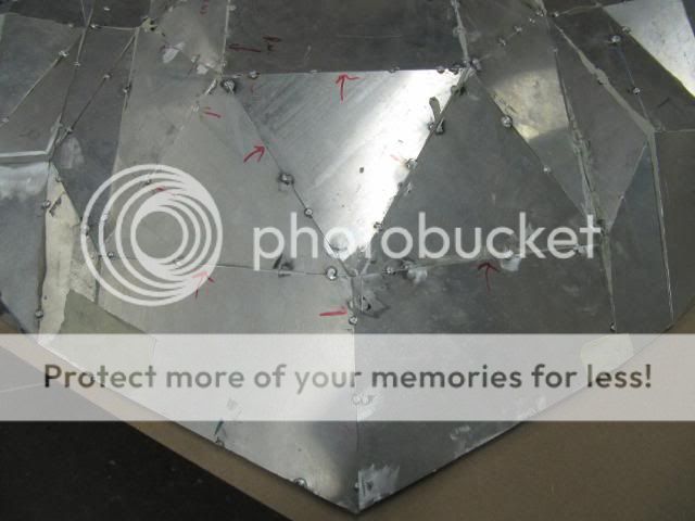
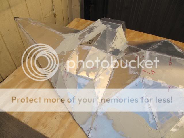
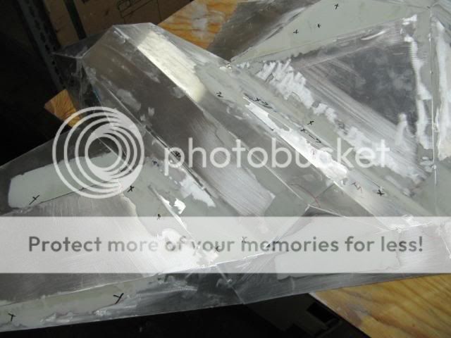
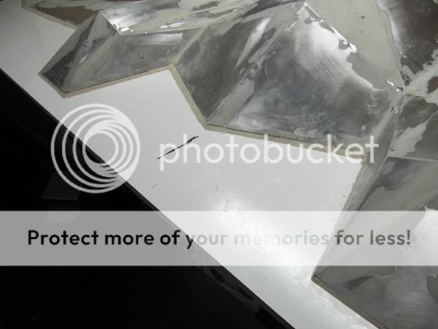
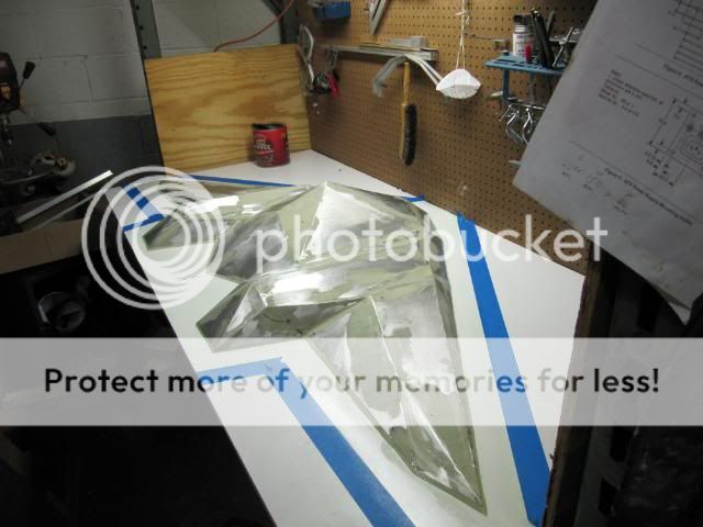
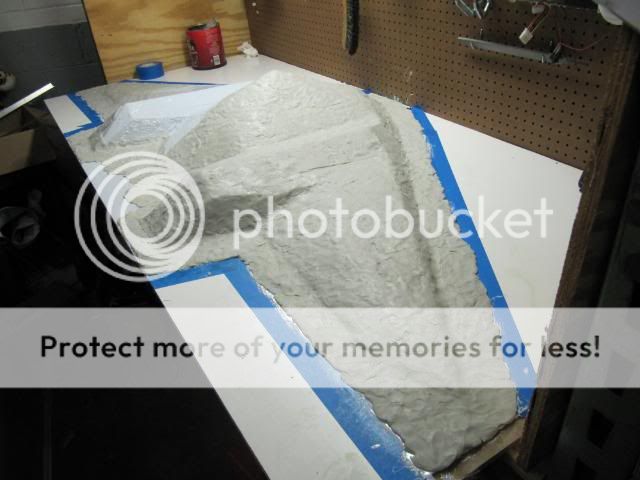
I started on the bottom of the entire assembly this weekend.

IMG_3214.jpg


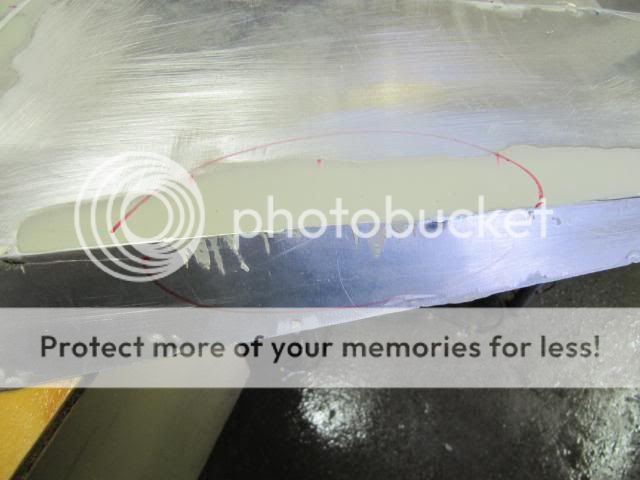
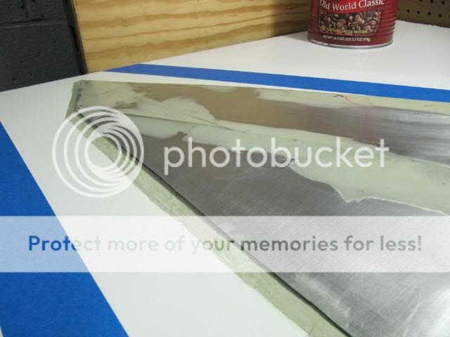
The bottom turns out to be a little more tricky than the top due to the mounting of the power supply. I already stated that I didnt like my initial render, so I re-designed the render this morning and went work on carving out the pieces for the main compartment.
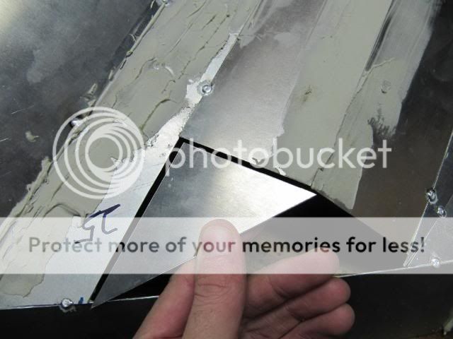
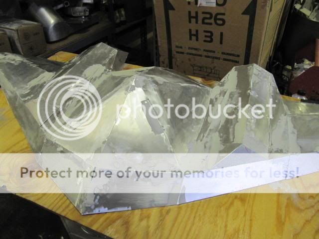
IMG_3215.jpg


IMG_3216.jpg


The front.

IMG_3217.jpg


IMG_3218.jpg


IMG_3219.jpg


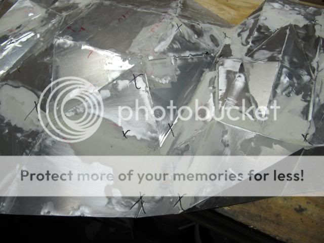
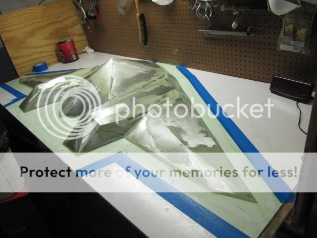
The power supply will pull the air in from vents, with those locations still to be determined, but the main fan will exhaust air straight out the bottom, as pictured.

IMG_3222.jpg


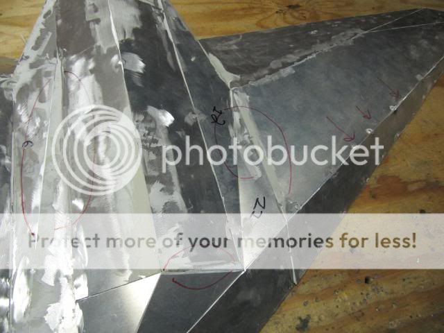
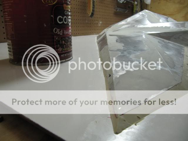
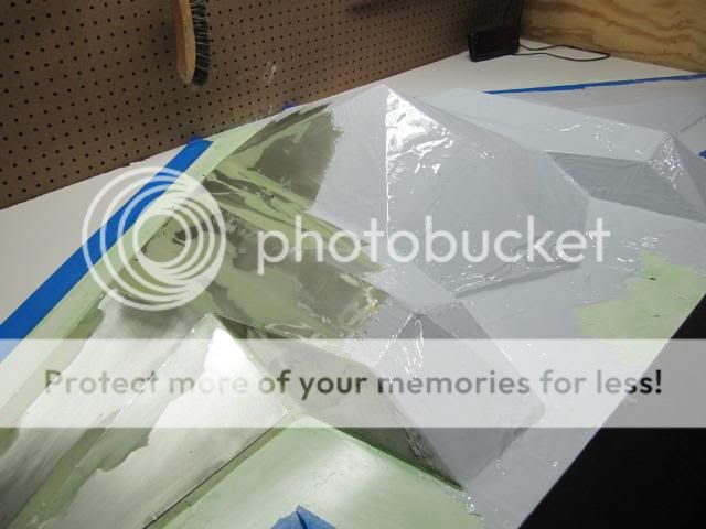
The pump is probably going to be located in the front section there. Lets you all see the room and clearance I will have to work with and it all looks good.

IMG_3223.jpg


IMG_3225.jpg


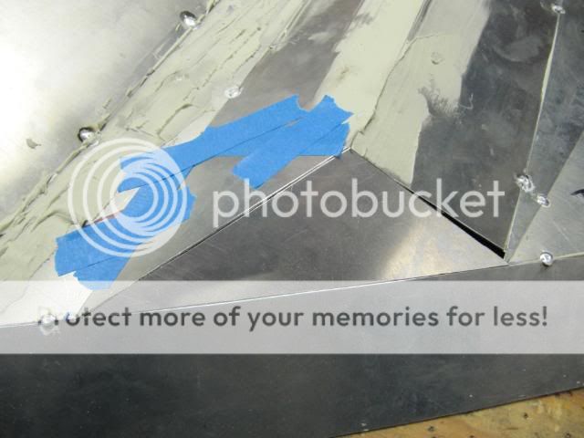
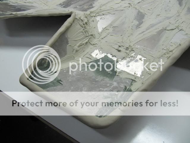
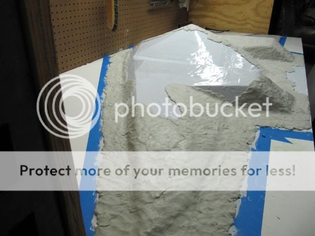
The power supply will be mounted in its current orientation. SR-X will be able to hold a 1200W power supply if needed, though, I dont think so, I over design at times.

IMG_3226.jpg


IMG_3227.jpg


IMG_3229.jpg


IMG_3233.jpg


IMG_3232.jpg


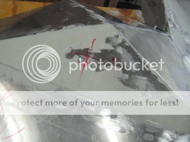
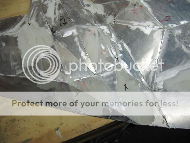
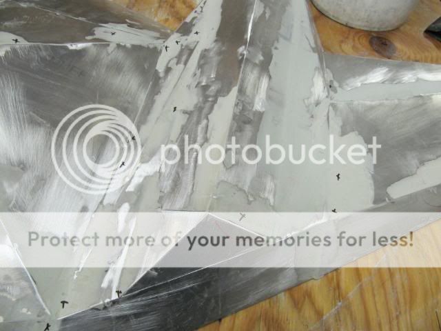
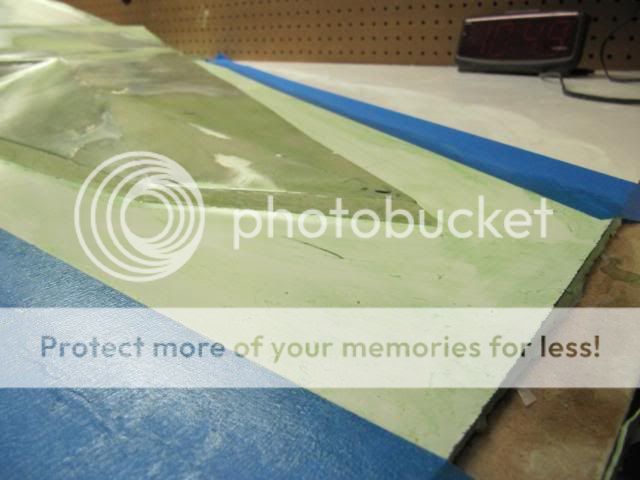
This work went fairly fast. I still have to go back and create two bulkheads that will hold the power supply in place and add support structure to the cover. I believe that I will do small angled brackets on the main frame pieces to hold the cover in this section.

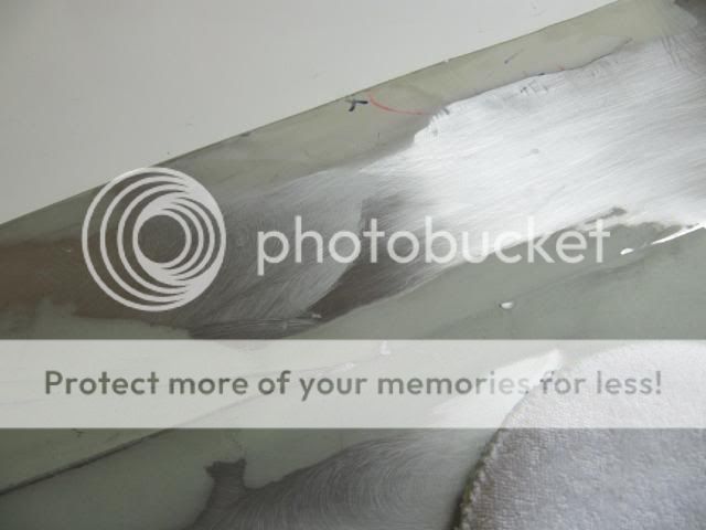
The optical device will also be located in the rear bottom of the case. I'm goin to try a slot-loading drive this time around. Will give a cleaner look.

That's all for now.
 
Hello! I've been in the doledrums of modding for some reason. Guess I'm playin to much MOH, gettin ready for BF3. Anyways, I been doing some modding here and there and now I am getting out of the doledrums.

I continued work on the lower wing.

IMG_3234.jpg


made myself a little diagram again and I'm off.

IMG_3237.jpg


I'm working from the front to the back, though, I can't exactly get around to the front, so I have to lean all the way over SR-X to do these measurements and stuff

IMG_3240.jpg


IMG_3242.jpg


IMG_3243.jpg


IMG_3244.jpg


IMG_3245.jpg


IMG_3248.jpg


IMG_3249.jpg


IMG_3250.jpg


These adjacent section went fairly quickly. I than stopped and took the week off and I than picked up and continued again on the lower radiator section portion

IMG_3271.jpg


IMG_3272.jpg


IMG_3281.jpg


IMG_3283.jpg


IMG_3284.jpg


IMG_3282.jpg


IMG_3285.jpg


The lower radiator portion is now finished.

I did talk to my friend Andrew this week about the plan for welding. The welding of the cover may not happen till September due to busy schedules. I am anxious to get past this, so I can begin constructing the exterior mold box.

The next step after the bottom wing segments are complete is to fabricate the supports for SR-X. There will also have to be additional bracketing made along with custom housing. That's it for now
 
Hello. Lets get right to the work!!

IMG_3287.jpg


I went ahead and finished off the rest of the lower wing assembly. In this work there is good cause for error, due to differing angles between the top and lower wing covers. Ultimately when I take the wing portion off for main strut supports, I will see how good my fabricating and measurements were and will make changes accordingly.

IMG_3288.jpg


IMG_3289.jpg


I am in need of advice on good alternative epoxy or glue for the seams!!!!

IMG_3290.jpg


I had to rip apart the main compartment section next, because the covering's were off and had to be remade. This also let me contemplate more about exactly how to fasten the power supply in place.

IMG_3291.jpg


IMG_3292.jpg


IMG_3293.jpg


IMG_3294.jpg


IMG_3295.jpg


End of Part 1
 
Part 2.

Main Strut Support / Landing Gear, if you want to call it that

I thought for a long moment about doing actual replica landing gear for this build and whether they should be retractable. I made the decision Not to due it, cause this is not a true flyable R/C aircraft. This is a computer which should adhere to its own style. I would never use the retractable landing gear, so it would be impractical to go thru all the work. Would it be awesome!!! Ya it would, though, I'm going to have to mount this on the top of my truck for transport in the end. Anywayz.....

IMG_3296.jpg


I had a solid design in the my head and tried to sketch it on Google, to no avail. Back to fabricating straight from my head. I wanted the design to be triangular and slanted, for an agressive stance and look.

IMG_3297.jpg


IMG_3298.jpg


IMG_3299.jpg


IMG_3300.jpg


IMG_3301.jpg


IMG_3302.jpg


I than labeled and disassembled the wing sections so I could cut and make the proper bracketing for the Main Supports.

IMG_3305.jpg


IMG_3309.jpg


IMG_3310.jpg


Had to remove some screws and cut into some brackets.

IMG_3311.jpg


IMG_3313.jpg


IMG_3314.jpg


Cut out a plate that the main support will be bolted to from the top. The top and bottom sections of the Main Support or made out of .090 Alum, which it thickness, gives me the ability to tap and bolt.

IMG_3315.jpg


IMG_3316.jpg


IMG_3317.jpg


IMG_3318.jpg


IMG_3319.jpg


I dont know if I will make a lower cover for the Main Support compartments. I'm thinking about it though. I should have the entire frame off the bench this weekend on it supports.

I'm still in frame work construction and still have the styling portion of this build to move onto. Getting more excited by the day cause I am moving closer to molding and vacuum infusion!!!
 
Finishing off this weekend's update with installing the main support's on SR-X and getting the build off the bench!!:dremel::clap:

In a situation like this, I can't full pre-determine how the build will sit balance-wise. I guess if I had intimate CAD with animation knowledge, than that answer would be yes, but for me, it is just visualize, fabricate, and have faith.

IMG_3322.jpg


Have to finish fabricating the supports. Which means drilling and taping for the bolts to hold the supports to the frame pieces.

IMG_3323.jpg


IMG_3324.jpg


IMG_3325.jpg


I aligned the support piece to the frame, so to make sure that the support is aligned straight.

IMG_3326.jpg


I figured out an location for the Main Compartment support, which will sit behind the front bulkhead. The reason for this location is the bolts are out of the way and it seems an ideal location for center of mass. Hopefully

IMG_3327.jpg


IMG_3328.jpg


Taping 10-32

IMG_3329.jpg


Installing

IMG_3330.jpg


Ya that is my verison of cheap welding, lol!

IMG_3331.jpg


IMG_3332.jpg


The Result!!

IMG_3333.jpg


IMG_3334.jpg


IMG_3335.jpg


So I have some slight problems. First, I noticed that the SR-X was slighty tilted towarded that back. Second, I noticed torsion being exhibted in the radiator compartments.

Overall, not to big of a deal. When the radiators are installed, those compartments and there torsion effect should disappear. What I did for the slight tilting is what I am about to show you next.

IMG_3338.jpg


I removed 20mm from the front support. Now SR-X slightly tilts toward the front and the torsion also disappears slightly, due to the re-alignment of the center of mass. That is my best guess.

IMG_3339.jpg


IMG_3341.jpg


Now to get those radiators on order and installed this week!!!:dremel:
 
Easily one of the coolest mods I've ever seen, and it's not even done yet! Thanks for sharing.
 
Finally, voided a power supply for the first time, I think?!! I may ditch the surrounding housing for an "external" look. That would be really awesome if people could view the power supply from underneath, somehow, and actually see its insides, instead of a box. Problem is that, the compartment for the power supply will be sitting so low, that, that wont happen, unless I put a arcylic window in, hhmmm:dremel: Anywayz....

IMG_3342.jpg


IMG_3343.jpg


Thanks Thermaltake, you guys rock at building power supplies! Serving me well for over 3 years.

IMG_3344.jpg


The big debate!!! If I leave it all exposed, there is the chance it could short-out somehow. Secondly I would still need to provide a cooling pathway for the power supply. I thought about it for awhile and I figured I'd roll with some sort of Alum. housing to cover the power supple.

IMG_3345.jpg


Now to Bend

IMG_3346.jpg


IMG_3347.jpg


IMG_3348.jpg


IMG_3349.jpg


IMG_3350.jpg


Last bend and...

IMG_3351.jpg


wow, that came out pretty awesome looking!! Wait, it jus a plain cover. I sitting back and thinking about the styling for this cover. So No cutting for now.

IMG_3352.jpg


IMG_3353.jpg


Good fit with plenty of clearance. Now I have to go pick out a fan, which is crucial, to the overall look and meaning of SR-X.
 
Hello. Weekend Update. Radiators

This past week I order two Black ICE 360GTX's from mountain mods. They had a great price on them at a 107 a piece. Finally got them in Friday, see below.

I wanted to go with Thermochill or even X-Feser radiators, though, the dimensions on their thickness would have required the whole build to be bigger. Every half an inch in gain, requires the geometry to be altered in order to balance out the looks.

IMG_3354.jpg


IMG_3355.jpg


Test Fit. Fits like a glove.

IMG_3357.jpg


IMG_3358.jpg


IMG_3359.jpg


I de-assembled both wing and from the pics above you can see that there is a considerable gap in the rear of the compartment. The gap is for the tubing and such, without this gap, I would not be able to correctly put tubing in. That is what Sketchup is showing me at least.

IMG_3360.jpg


I really had a debate over bracketing. I wanted something simple and lightwieght. So alot of ideas trasversed my mind. I couldn't put a bracket on the top of the radiator due to the fans and clearance problems. I didnt want to replicate how I did the bracketing on my previous builds. So I turned to putting the bracket on the bottom. I had some thick angle Aluminum lying around that would just do the trick.

IMG_3362.jpg


IMG_3367.jpg


some drilling and bolting. Most of you may think, that is alot of fastners!!! Ya it is, the radiators mountings helps make SR-X more rigid. I had some torsion issues, with the radiators helping in solving that torsion.

IMG_3366.jpg


IMG_3368.jpg


IMG_3370.jpg


Both sides of the brackets for the radiator. Now I just had to drill, cut, and mount the radiator to the bracket.

IMG_3372.jpg


IMG_3373.jpg


Cutting and filing.

IMG_3377.jpg


IMG_3380.jpg


IMG_3379.jpg


Installing the radiators and their compartments back onto the frame.

IMG_3383.jpg


IMG_3382.jpg


IMG_3381.jpg


I happy with the brackets and the look. A bit of the torsion what away, and as I install the lower bulkheads in the Main Compartment, the torsion should nearly all go away. Plus once the lower cover is installed the frame will conform to the space of the lower cover, diminshing any torsion that could still be there.
 
Hello. It has been a long time since I have done an update on the Log. For the last month and half SR-X sat up in weld shop being a dust collector. Our factory is at full-load at the moment with production and there is no time, even after hours, for work to be done on SR-X. So I had to make a tough call and go pick up SR-X and get it welded here where I am at.

Luckily there is a weld shop right next door that we use all the time, though, there work can be OFF at times, as you will see.

IMG_3394.jpg


The left wing welded up.

IMG_3395.jpg


Top View

IMG_3396.jpg


The inside of the main cover.

IMG_3397.jpg


Argh!!! Man oh Man!! So the welder didnt know that these pieces were precision cut. He jus welded them any which way I guess and this was jus one of the end products.

I do like to do medicore work and try and cut corners. So I began cutting out and re-fitting all the pieces that were welded wrong. As you will see in the next group of pics.

IMG_3398.jpg


IMG_3399.jpg


I re-taped the covers and will head over to the weld shop tomorrow. I will be exacting in what I am exactly looking for and will probably lend a hand in holding some of the pieces while they are welded on. The process shouldnt take too long, plus the two remaining radiator sections, the guy will know what to do.

I give it about another week before the covers are completely done being welded. In the meantime, I will be ordering fiberglass bondo and regular bondo in order to get ready for mold. I will also get my substraight that these covers will be placed on for the mold process.

I will have an indepth walk-through and tutorial once the mold and carbon fiber go down. Stay Tuned.
 
Hello. Thanks for all the support!! I finally got the top cover completely welded today...but before I get there....

The Vacuum Pump.

IMG_3400.jpg


This will be the Vac. pump I use to do the resin infusion. It is made for a 500lb marinading machine for food. Did I mention that I got this for FREE!

IMG_3401.jpg


Took these filters off, though may use these later.

IMG_3402.jpg


more filters, very nice to have these though.

Top Cover.

IMG_3403.jpg


I probably should have taken some pics during welding, though, we were moving pretty fast and there was no time to stop and take a kodak moment.

The process in which we went about welding that I formulated was to start from one side and work our way over welding the sub assemblies together. I dont recommend trying to weld each piece at a time like this. Put your assembly together and break it down if you have to into different sub-assemblies and than tape it those together and proceed to weld.

I tried to keep the welding to a mininum due to the possible warping of the Alum. This is only .040 thick, so make sure if you are welding thin material to have a good welder on hand or constant burn thru's will happen.

IMG_3404.jpg


IMG_3405.jpg


IMG_3406.jpg


IMG_3407.jpg


IMG_3409.jpg


Tomorrow. I will do the bottom cover completely. I am feeling the Mold and Carbon Fiber happening real soon NOW! Questions jus ask. I think that is all for now...
 
I can't wait to see the carbon! Where are you getting your supplies? US Composites?
 
Hello. Yesterday I got the bottom cover welded up. I am stepping closer to began the Mold process. I am in uncharted territory, or that is at least how it feels right now.The reason is because the top cover came thru the weld process with some wrap, though, the bottom cover experienced alot of warp due there being more pieces than the top cover.

So I have to figure out a way to make the top and bottom cover align properly. While there will be significant pull down in the fastening process once the covers are fastened to the frame, the gaps should be minimal and not a alot as you will see. Input would help!! A

IMG_3410.jpg


The bottom cover sitting atop the Top Cover.

IMG_3411.jpg


IMG_3412.jpg


IMG_3414.jpg


____

IMG_3415.jpg


Here is the frame sitting in the bottom cover

IMG_3416.jpg


IMG_3417.jpg


some of the lines look good.

IMG_3418.jpg


The triangular pattern should help air be exhausted out of the back by creating turbulence and it also looks really cool:thumb:

IMG_3419.jpg


About those gaps! This is what I am talking about. While the fastening process will draw this down, some of the gaps here are off and dont not align so I am trying to figure out without ripping the welding apart on how to fix it. hhhmmm

IMG_3420.jpg


IMG_3421.jpg


Problems back here also

_____

In order to make sure the cover it sitting flat I went to Home Depot and got a sheet of MDF board. This will help me make adjustments and it will also help when bondo'ing and with the mold process. More on that later. If you are building a cover like the way I do, this is a good idea.

IMG_3422.jpg


IMG_3423.jpg


IMG_3424.jpg


The top cover sitting pretty flat on board. The edges are mostly touching the MDF board. When the top cover sits on the frame the alignment and gaping is quite good.

IMG_3425.jpg


IMG_3426.jpg


I started taping the cover down so when I go to bondo it doesnt move around. Before I begin to grind away the excess weld I will apply bondo to prevent further cracking of the welds because if I jus straight went away at grinding the cover would like fall into pieces and it cant be welded to much due to possible warping so finding that medium is crucial and a pain.

Back for more tomorrow hopefully.
 
Beautiful!!!! I can't wait to see the finished product.
Should definitely keep the PSU covered, even one drop of water can mess it up, ask maxishine =)
 
Hello. Full Steam Ahead!!! I got the 3M filler in today and immediately got into the case build when I got off work.

IMG_3428.jpg


3M MarGrip 2 is bondo made for extreme adhesion on difficult surfaces like Alum. I also perfer
3M over all other brands due to the ease of sanding. They just make great products. This gallon only cost me about $40 on Amazon. Which is a great price.

IMG_3429.jpg


First batch. Always try to work with Filler in a well ventilated area and if indoors do wear a mask of some type.

My 3M filler Theory: When doing a cover that is cut-out from pieces and than welded there will be warped involved from the welding. You will not totally be able to seam weld the cover, unless you invent some exotic process that will cost you ALOT of money. So, instead, my theory works like this. Tac the seams and than go back over the seams will Filler. The filler will make the cover more rigid, so that any future work done on it, it wont just fall apart. You could substitute Filler for an adhesive substance, though, Filler is as much as an adhesive as other products out there.

I just need to get a nice clean surface to mold with. Different outlooks or scenarios will require different products and methods.

IMG_3430.jpg


IMG_3431.jpg


I started by covering up the gaping gaps in the covers. Make sure to apply a very thick coat. This will just be sanded down later.

IMG_3432.jpg


IMG_3433.jpg


I flipped both covers over and applied filler to the inside. I WILL NOT be sanding the inside of the cover sense it will not be used for any part of the mold per se. All I care about if the Top face. So I applied a thick coat on the inside seams and gaps.

IMG_3434.jpg


Trick of the trade is to use your finger to do seams.

IMG_3435.jpg


IMG_3436.jpg


IMG_3437.jpg


This last photo I had to break a weld and do some manual bending and forcing to make the cover sit flat. I used on tape and wieghts to get the cover where I wanted it. When it was positioned right, I applied Filler to make it hold, hopefully, in the morning I shall see.

IMG_3438.jpg


To show some of the seapage that occurs which is actually what you want cause you know the seam is being completely filled.

Back tomorrow for more updates.
 
Keep up the good work! Hopefully the body filler works well for you.
 
Been apply'n filler along the seams for the past day or so. Got the covers to the point where they can be handled without worrying about them falling apart or the weld coming undone.

One of the task that I needed to tackle was covering up the Exhaust outlets on the rear of the covers for the Infusion process.

IMG_3442.jpg


IMG_3443.jpg


IMG_3444.jpg


Put tape along the seams to hold in place.

IMG_3445.jpg


IMG_3446.jpg


IMG_3448.jpg


IMG_3449.jpg


IMG_3450.jpg


Pretty simple task.

I flipped the cover over and applied tape on the outside of the cover. The reason for this is I would use Filler to glue the seams together on the underside to hold the pieces together.

In the mold making process and the Infusion process my theory is Not to have big gaping sections that would have to filled with regular putty. Instead I decided to cover those sections to save on possible future Infusion headaches but also to make sure the resin flows properly across the entire mold. By doing it without those covers, the Resin and setup could lead to failure.

IMG_3451.jpg


IMG_3452.jpg


IMG_3454.jpg


This is the underneath of the Top Cover with the Filler along the seams.

IMG_3455.jpg


Theses covers are not flat but have a pitch to them.

IMG_3456.jpg


finally got around to cutting out and fitting the last wing piece. I need to hold this down while the Filler cures. Stay Tune on this one....

Back tomorrow hopefully.
 
Its been a busy day in the laboratory...

IMG_3457.jpg


Started the activites with the hand grinder.

IMG_3458.jpg


IMG_3459.jpg


Worked on grinding down the welds and access filler. I completely grinded down the bottom cover so I could move my hand across the cover without any major bumps.

IMG_3460.jpg


This is my first time using short hair filler. From what I hear this stuff is really strong. Been thinking about possibly using this as a backing for the upcoming mold, though, dont know yet. Still pondering on it...

IMG_3461.jpg


IMG_3462.jpg


IMG_3464.jpg


IMG_3465.jpg


I got to work on some loose ends and seams that kept breaking. I didnt want to re-weld those spots, so I figured I'll try out short hair filler and see how it holds. The filler comes out of the can really thick, about twice as thick as regular filler. I filled the end that will later get grinded and sanded down to match the top cover corner where the meet one another so they are symmetrical.

IMG_3466.jpg


Next task was to tackle those inlet covers.

IMG_3467.jpg


IMG_3468.jpg


IMG_3469.jpg


Cut, taped and flipped to get ready for filler.

IMG_3471.jpg


Gettin ready for the inlet covers wanted to show off the short hair filler. Reminds me of a toxic waste in color

IMG_3472.jpg


IMG_3473.jpg


IMG_3474.jpg


I made sure I sanded the areas first for better cohesion and than I waited and waited!!

IMG_3475.jpg


IMG_3476.jpg


IMG_3477.jpg


Finally after the short hair filler dried I was able to take the cover outside to finish it off with regular filler. The weather got nice today around 55F and I wanted to avoid stinkin up the shop.

I highlighted with a circle on the covers where I needed to go over. You probably will not be able to make it out. Just mentioning because it was a new task I did, which, helped me remember all the areas that needed attention.

Doing a final sanding tomorrow and this cover maybe ready for the mold process:clap::clap:

back tomorrow.
 
Hello. Been busy sanding away. I was suppose to update a couple days ago, but just have to been too heck it lately... so anyway

IMG_3476-1.jpg


IMG_3477-1.jpg


These coats are the initial coats of filler onto the covers. I waited until they dried and than sanded.

IMG_3478.jpg


IMG_3479.jpg


After sanding I went back over the covers with my hand and felt for areas that needed more filler. I marked them out with a marker. Some more pics below.

IMG_3480.jpg


IMG_3481.jpg


IMG_3482.jpg


IMG_3483.jpg


IMG_3484.jpg


I emphasis this because the mold needs to be near perfect if not perfect when doing a material like CF. Any little bump or ridge with be captured by the molding process and transferred to the cloth. It is time consuming but it will reflect itself in the final product. I pay close attention to details myself. So I endlessly am rubbing my hands over the covers which some ppl look at me like I am wierd but it is the good trait god gave me.

IMG_3485.jpg


IMG_3486.jpg


Same process. I marked the cover and begin to apply filler for the next sand.

IMG_3487.jpg


IMG_3488.jpg


IMG_3489.jpg


IMG_3490.jpg


Right now I am currently finishing up sanding and making some changes to the cover. More on that this weekend.
 
Keep up the good work. I feel your pain when it comes to body filler. I have been up to my elbows in it for the last two weeks.
 
Mold Making Tutorial

This tutorial will go over the process of making a mold for your project. Whether it is a small mold or a big mold, such as, mine is, this tutorial should give you insight and time-saving research into how to make a mold. I will list the materials needed and the pros and cons of the mold making process and what variable's to watch out for. I personally tried to hunt down a good tutorial on the internet and couldn't find one, so now I am writing one.

References:

http://www.compositescentral.com

This is a great website to go-to for information and help on making molds and composites materials in general.

http://www.carbonmods.com

They have a great youtube video on making a mold.

List of Materials Needed:

  1. The form you are going to make a Mold of
  2. Partall Wax #10
  3. Partall PVA
  4. Gelcoat: Polyester or Epoxy
  5. Reinforcement: Fiberglass or Putty
  6. Non-Hardening Modeling Clay
  7. Gloves, Mask, Razor Blade
  8. Wieghing Scale

IMG_3497.jpg


Here is the picture of the material that I will be using

The Mold Making Process

Now that you have assembled your materials, A plan needs to formulated for how to construct your mold! Remember always take your time and have patience. Rushing into the mold making process can lead to failure down the road.

IMG_3495.jpg


IMG_3496.jpg


Make sure you have a flat sturdy surface followed by a material that you can apply Wax to. In my process, I chose Whiteboard from Home Depot due to the size of my mold. The cost for a piece of Plexi-glass or glass would be too costly for me. This whiteboard is coated with a ceramic paint which is intended for bathroom construction involving water, so I will be able to wax this surface.

You can use a bare wood surface, though, I have been told not to due so, due to the porosity and texture of the wood could cause a mechanical lock and make the mold surface not flat.

What is Mechanical Lock?? Mechanical Lock in a mold is where the bonding surface such as, Gelcoat binds to the Form that you are making a Mold of. In the end, you will not be able to release your form from the mold thereby creating a lock and potentially ruining your mold.

IMG_3498.jpg


Place your Form/Part on the base board. It should sit considerably flat. Ideally the flatter your Form sits against the base board surface the less modeling clay barrier you will have to use.

IMG_3509.jpg


IMG_3501.jpg


IMG_3502.jpg


The next step is placing modeling clay along all the edges of the Form that come in contact with the base board. Pretty simple task. Use non-hardening modeling clay from any arts and craft store. Roll into a round long bead and push and stick on the edge than flip your Form and push it onto the base board.

I tried this method and than tried to flip the Form over and the clay fell right off. Time to improvise a new solution.

IMG_3511.jpg


I took my Form and traced an outline onto the board than I applied the modeling clay along the outline of where I knew the edge was going to be.

IMG_3512.jpg


IMG_3513.jpg


I took the Form and placed it onto the modeling clay and very carefully pushed down into the modeling clay the best I could.

IMG_3514.jpg


I went around the edge of the Form trimming and adding modeling clay where needed to prevent the mechanical lock from occurring. It is BEST to try and have no gaps between the modeling clay and the Form's edge. Try to make the surface of the clay the smoothest you can.

The next following Steps in the Mold Making Process are crucial!! Here is the Basic Method:

  1. Wax : 5-10 times with buffing between each wax coat
  2. Apply PVA: which is mold release agent. Typically 1-2 coats.
  3. Apply Gelcoat: Millimeter thickness depends on your plan
  4. Apply Reinforcement: Fiberglass or Putty like substance
  5. After Mold is cured: De-Mold

IMG_3515.jpg


IMG_3516.jpg


IMG_3517.jpg


Partall Wax #10 is the most commonly used wax on the market in the mold making process. There are different wax's, please do your research and be informed about how these other wax's could affect your mold making process. This wax is economical in price, about $10 for this can here.

Apply your wax coat and wait for the wax to dry and than buff the wax coat. Your drying time will depend on the temperature, humidity, and wax vendor you are using. Once again you will want to do this at least 4-5 times before applying PVA.

Wax helps in the releasing of the Form from the final mold. The more layers you apply the easier the De-molding process will be.

IMG_3518.jpg


IMG_3519.jpg


IMG_3520.jpg


IMG_3522.jpg


IMG_3530.jpg


IMG_3531.jpg


PVA: polyvinyl alcohol is used as a release agent in the molding process. PVA will create a barrier on top of the wax for further release help in the de-molding process. Using PVA is MUST in the mold making process.

Please where a ventilation mask and gloves when using this product. Make sure you have adequate ventilation. PVA does not smell good and is sticky on bare hands.

You can apply PVA by either spraying in onto the Form or you can rub it on with a cloth. Spraying will lead to shorter drying time while the cloth method will take longer. Spraying is about 15 min. depending on the thickness and environmental conditions, while cloth is usually around 45 min. Don't spare the PVA, this stuff is economical, $20 for this gallon.

The application is also simple. Simply just rub on the form surface making sure to go over the entire surface esp. the corners. After each coat wait for the coat to dry before applying the next coat.

I applied 3 coats to my Form.

IMG_3523.jpg


IMG_3524.jpg


IMG_3528.jpg


IMG_3529.jpg


IMG_3532.jpg


After the Wax and the PVA have been applied it is time for Gel-coat. What is Gel-Coat?? Gelcoat is the actual finish mold surface of your part. It should be as smooth as possible when finished curing. In the process of mixing and applying Gel-Coat you can get tiny air bubbles. Depending on the type of Gel-Coat you are using, will determine the probability of developing air-bubbles.

There are two types of Gel-Coats: Polyester and Epoxy.

Polyester gel-coat is used when no backing reinforcement is needed. It drys to a non-tack finish, hard, high gloss finish. If attempting to use a backing reinforcement, a primer coat is needed for adhesion between the polyester and whatever backing coat your are using. This is typically NOT done this way. I have found that this is mainly used in the boating industry for repairs on the outside of fiberglass hulls.

Epoxy gel-coat or surface coat as it maybe called is used when a reinforcement layer is needed. It also drys hard, but tacky, with a glossy finish. Epoxy is suited more the tool making industry in which molds need to be made and used over and over again.

There is alot more science behind the two gel-coats. Do your research and determine what is best for you and your process. If you are making a mold like mine, Epoxy is preferred.

The application is a little in-depth. You will need a wieghing scale and some cups and stirrer. The material you are using will have a mix ratio, usually done by wieght. Gel-Coats are made of Resin and a Hardener, where you will have to mix to the two. Some basic math will have to be done. I am using RenGel 1118. It has a mix ratio of 100:9 by weight. So 1 lb of material Resin will need .09 lb of hardener. Make sure to Tare out the cup/container you are using so not to throw off your mix ratio and to insure the proper mix.

Mixing the two together can be simple or difficult, depending on the density of your material. The thicker the material the more stirring is needed. Which means the more chance for air bubbles and vice versa. It is generally recommended NOT to mix to rigorously. I had to mix rigorously due to the density of RenGel 1118.

Once you have mixed your Gel-Coat you are fighting against time. You will only have so long to apply your coat before is drys. It drys Hard. The time can vary depending on your product and conditions of the room environment. RenGel 1118 has a 30 min. gel time. The last picture above is Ren gel-coat.

IMG_3533.jpg


IMG_3534.jpg


IMG_3535.jpg


I used a bristle brush to apply the gel-coat. I tried to make it as uniform in thickness as I could. I got about 1-2mm thickness out of the coat. You can apply more if needed. It is recommended to get the corners with thicker coats due to higher stresses in those spots when the mold is being used. RenGel is expensive. $49 per quart of Resin with $16 for the hardener. I used two quarts on this cover. Each Quart can cover 900 square inches approx. Your product may differ. Once done just wait for the gelcoat to dry. This is epoxy coat so the surface will remain tacky so a reinforcement can be applied.

IMG_3536.jpg


All-Fix is a two part putty the hardens. There is little shrinkage in the product, so the chance of cracking is rare.

The more common material used for reinforcement of a mold is Fiberglass. I did not chose fiberglass due to cost, health concerns, and that air bubbles can burst thru your gelcoat. I dont have the necessary ventilation and equipment to due fiberglass, which is my health concern. The cost between fiberglass and All-Fix was almost the same. The air bubble effect is what concerned me in the end. This phenomenon has been reported over at Central Composites by other users. When they de-molded, they found bubbles had burst their way thru the gelcoat leaving a cavity in the mold surface. They typically have to start the mold process all over again. Fiberglass application created a exothermic effect. It created heat and alot of it. This heat can cause your gelcoat to break down and air bubbles to push thru. Due to time and cost I searched out a alternative solution which was All-Fix. Carbon Mods uses a similar substance in their mold making video.

IMG_3537.jpg


IMG_3538.jpg


IMG_3539.jpg


After mixing All-Fix putty I applied it to the gel-coat. Simple application in just rolling it out on a flat surface and placing it down and patting it down. I made sure that the reinforcement layer was really thick. The cure time is 24 hours.

So.......I ran out of All-Fix and I substituted in Short Strand Fiberglass filler in for the All-Fix.

This was a solution presented to me by my cousin. He had done the process this way before. The short hair filler still gives off heat so I placed a fan above the filler to help cool the filler off while it was drying. This material will dry to the hardness also that I desire, since I have already used it in gluing edges together on the underneath of the covers.

IMG_3540.jpg


IMG_3541.jpg


Now I wait to De-Mold and see if the process is successful.

Questions and Comments or advise don't hesitate to ask or write.

I hope this tutorial has been helpful to those looking for guidance and information on the mold making process.
 
Great work...or at least I hope! When will the mold be released?
 
Is this a PC or a classified CIA program for a new spy drone?

That thing looks like it going to take flight. Amazing.
 
This is pretty amazing. Not many men out there with the skills or desire to do something like this anymore.
 
you are the fuckin man.

kudos for doing something that includes so much hard work and dedication.

thank you for sharing.
 
Hello. Was sitting back today and it occurred to me that this could the largest mold made for a computer in this community:rock:!! I was getting nervous that the cover would not release out of the mold...wondering if something went out wrong in the wax and pva process...well....

This morning started out by flipping the mold over.

IMG_3542.jpg


The mold was heavier than I expected. It was awkward in handling in it due to its size.

I started by knocking around on the wood base board around the mold. Than the wood started to release from the front of the mold.

IMG_3543.jpg


The base board to a little effort though it peeled right off. I didn't know what to expect next. This is my first mold!! I was wondering if the texture from the base board was going to turn out horrible, though, it didn't. The flange area turned out just great. The base board was not ruined.

Below, I was left staring at the cover now inside the mold. Wondering how the heck am I going to exactly going to get that out. I knew so far that the Wax and the PVA were working like they are suppose too.

IMG_3544.jpg


IMG_3545.jpg


My plan was than to take a razor blade and carefully ease up the edge so I could get in there with some pliers. I knew that the cover would come apart in pieces due to its construction. There goes all that Hard Work!!:wallbash: Oh well, its worth it.

IMG_3546.jpg


IMG_3547.jpg


After ripping all the pieces out this is what the cover looked it. Now time to scrap!!

IMG_3548.jpg


My co-worker built me a wooden frame to sit the mold on. I cleaned some of the PVA that was still on there and still have alot of work to do. I have to sand in a few places and patch a few places where the gelcoat crack. Yes, gelcoat can be repaired.

IMG_3549.jpg


IMG_3550.jpg


IMG_3551.jpg


For my 1st mold, it came out good.

Here are some Molding tips that I have learned since De-molding:

  • Double-Up on Gelcoat around corners and fragile edges
  • PVA is your friend, Use alot of it!! Three coat worked great but I would go more, maybe up to 5.
  • Putty was a good reinforcement, though, Fiberglass is the best. Lighter wieght and stronger
  • Mix your Gelcoat, I had some place where the gelcoat was not mix good enough.

Now time to do the second mold and than Vacuum Resin Infusion!!
 
You have 24hours!


Then I demand pics!

Now they are up! Thanks

Is this a PC or a classified CIA program for a new spy drone?

That thing looks like it going to take flight. Amazing.

hahaha!!

This is pretty amazing. Not many men out there with the skills or desire to do something like this anymore.

Thanks! Thats an awesome compliment

you are the fuckin man.

kudos for doing something that includes so much hard work and dedication.

thank you for sharing.

Thank you for watching!! Luv the support
 
Awesome! That mold looks very nice, especially since it was your first one. I am really looking forward to seeing some carbon :)
 
Back
Top