[Project]: Big Bro' Prodigy (Extreme BitFenix Prodigy mod)

updatexg.jpg


UPDAAAAAAATE! :D

Cutting the chassis and mounting the motherboard plate. - 08/04 -2013

UPDATE 08/4 - 2013

Hello dear readers! :D

Long time no see, as they say. Joking aside, I am now back on track after a break from the project for about a month. But now I'm here to take it all by storm and I hope you are ready! :D

So we may all wonder what it will be about this time? :)
Last update was an unboxing of GIGABYTE z77x-UP7 while this time it will be modification related !

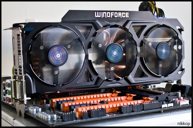
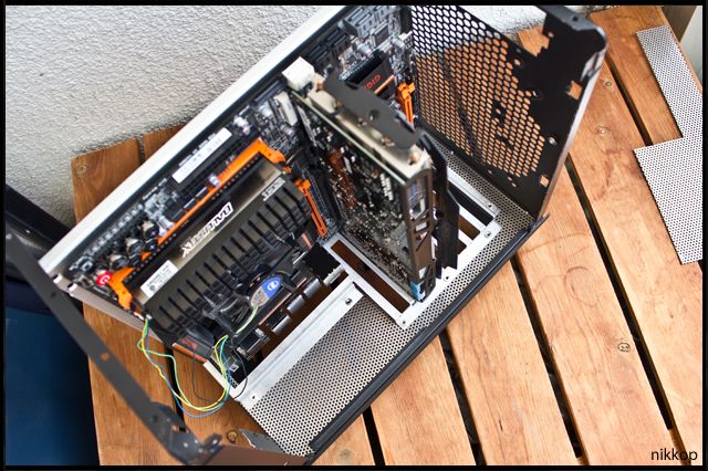
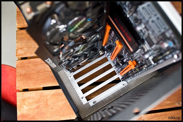
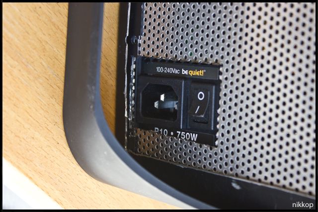
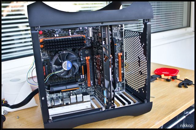
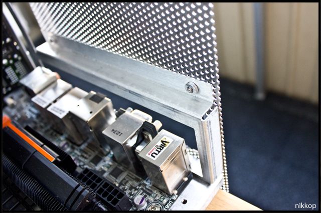
I showed this picture earlier in the thread to demonstrate how it looks when the motherboard is inside the chassis. However the motherboard is just inserted to see if it will fit, no modifications are made on this picture:
86241539.jpg


Now, I have come to the moment where the motherboard plate will actually be attached to the chassis. So I turned up and down the whole apartment during my modification. (My girlfriend is away otherwise it would have never been able to look like this at my home, hah!)

So yes, the update will be about how I manage to mount the motherboard plate by cutting the chassis. Enjoy!
__________________________________________________________

Here we have a picture like the above, that is a picture of how motherboard and motherboard plate looks like when it is inserted into the chassis itself (no modification made)
It's tight as hell, but it's half the thing, compact computing! :D
44316359.jpg


I devoted many hours to test fit and measure a lot to find out where I wanted the motherboard plate exactly! Given that I press into an E-ATX motherboard in an m-ITX chassis so it may get pretty tight on space, everything will be compact :)
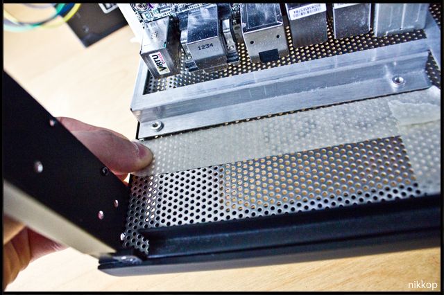
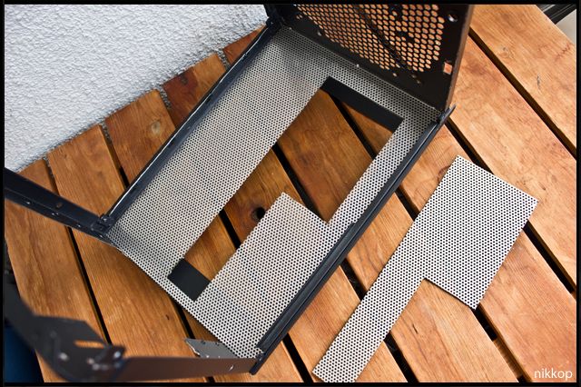
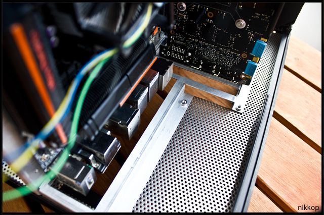
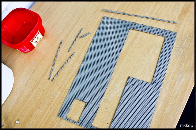
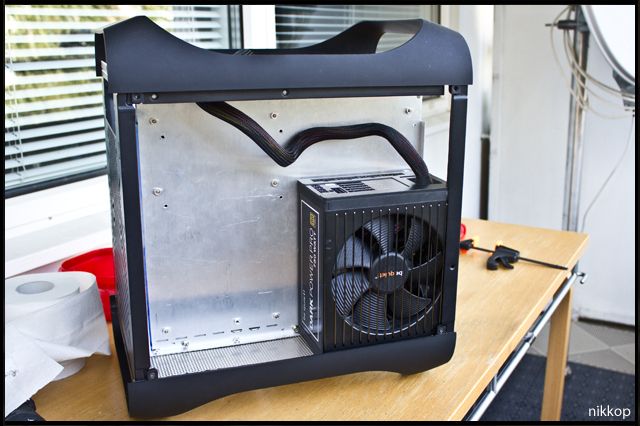
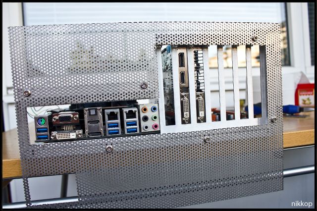
Anyway, after many hours of measuring, I concluded that I wanted it to be mounted exactly like this, using the holes in the bottom of the chassis as measuring points:
48921826.jpg


The actual I/O and PCI portion of the motherboard plate, seen from behind. This is how I want it mounted.
14701854.jpg


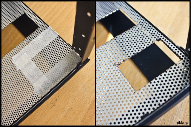
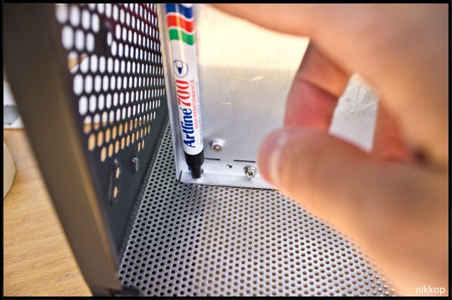
What I had to do then, because I can not cut on the inside of the chassis, was to turn the chassis so that the bottom was pointing upwards. Then I was able, with the help of the measuring points, to put out the metal pieces in the same place as if they were on the inside.
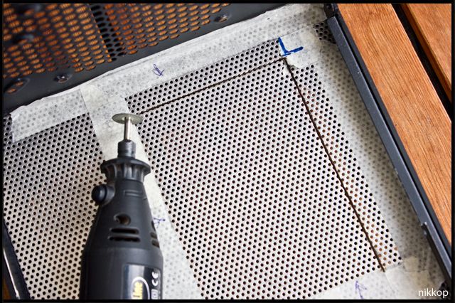
This made it possible for me to put up markers for where I wanted to cut. Since I have, literally, milimeters to play with in tolerance, it was a very careful job :D
66506671.jpg

42491006.jpg


Markings are made so now it's rock 'n' roll!
20436944.jpg


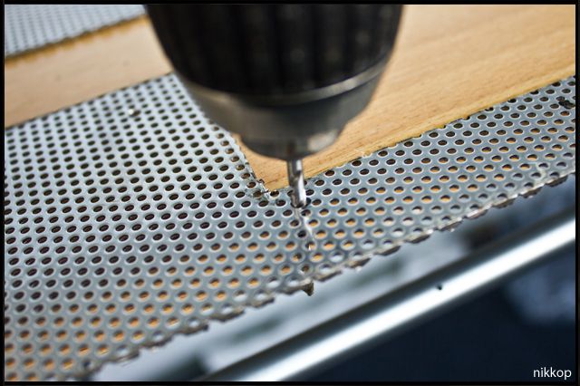
I call on my dear friend who will help me through this thick metal ;)
83944334.jpg


I start to saw and it goes fairly well! Becomes difficult to turn sometimes, but canbe done with some different methods. Have run out of blades for my dremel so the jigsaw will do all the work! :)
Here is how it looks when the I / O hole becoming sawn up.
73173524.jpg


Aaaaand it's gone!
90007535.jpg


I place the tray parts again to ensure that everything matches and is in place. I/O hole is now a hole and PCI-holes remain to be sawn, so far so good!
98243266.jpg


After I checked that everything is correct I continued to saw. I use these "things" to fasten and tighten some parts
61605300.jpg


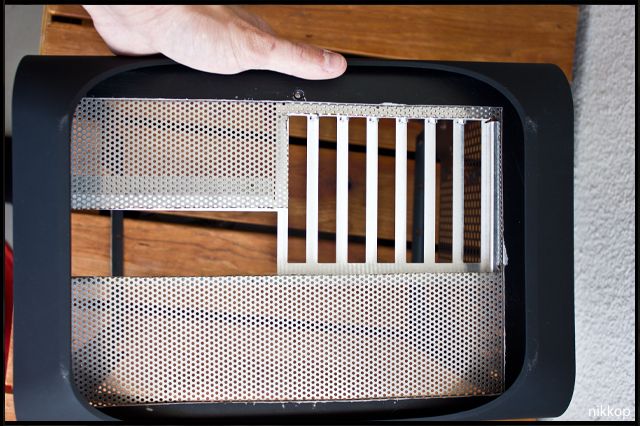
There you go! After many minutes of planning and sawing the hole is finished! Next up, the scary moment every time you saw something, did it turn out good ?
29675360.jpg


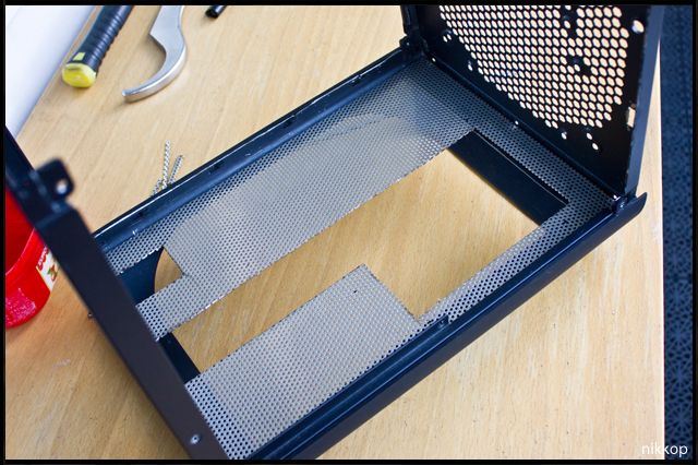
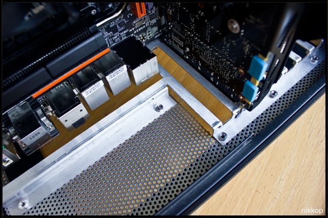
To make sure everything works I tested the plates by having one piece of sheet metal on the inside of the chassis and the other on the outside. I was extremely lucky as there was a screw hole in the chassis (marked with red arrow) that was in exact position to the motherboard tray holes. What are the odds?! I could therefore mount a screw to see how it was when attached
42294877.jpg

92577135.jpg


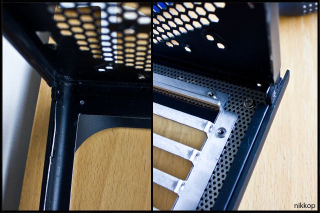
I turn the case over to see how it looks like from the inside, and damn! I was incredibly pleased with the outcome on the inside (the outside (bottom) needs a little work). I really like the looks of it.
I've also thought about coloring the motherboard plate black so it does blend in better with the black color.
98053139.jpg


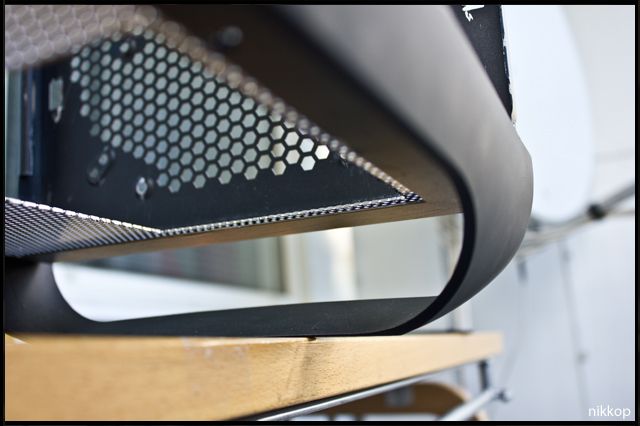
And then comes the big question, how does it look with the motherboard inside? :D Will it fit? Will everything will be according to my measures?
Honestly, everything was perfect :p Just as I wanted, is ill pleased and happy about it :D
The motherboard fits perfectly and now all ports are accessible on the underside of the chassis!
57350768.jpg

69292074.jpg

__________________________________________________________

As you can imagine, this was a vital part of the modification, cutting the chassis to get all ports accessible. Excuse me if I say it again, but I'm so happy with the outcome :D

What do you think of this result? Please let us know what you think about it! :)

Comment or ask a question if you'd like! I love when people write/ask/discuss about this project.
Thanks for reading and following!

Have a nice day!
Thanks in advance
Best Regards
Nikkop
 
Nice! Glad to see more progress on the build. I have to say your pictures have been very helpful with my own decisions customizing this case. I'm currently working on fitting an mATX motherboard. I'll probably end up buying a second and trying for a full ATX motherboard next!
 
This build is looking great. I almost want to copy the build and build one myself.
 
wondered what happened to this project. Looks sweet

It was on a short pause because of my need to study :(
Thanks tho! :D

Nice! Glad to see more progress on the build. I have to say your pictures have been very helpful with my own decisions customizing this case. I'm currently working on fitting an mATX motherboard. I'll probably end up buying a second and trying for a full ATX motherboard next!

Thanks a bunch! :)
Yea, I like to show everything pretty detailed so one, if one wants, could follow the same steps after I'm finished with the project :) Glad my project log have helped you!
My first plans were actually mATX, but then I noticed someone already did it and I wanted to be "the first", so that's why I thought I'd do something extreme as ATX/E-ATX ;)

This build is looking great. I almost want to copy the build and build one myself.

Thanks a lot! :)
Haha. Glad you enjoy it that much. I construct my project logs so one can follow in case they wants so you are free to do so ;)

By the way!

I've gotten some questions about the cables that are going to be attached and if they interfere with the floor or if the case's feet are high enough.

The answer is a positive one, the feet are high enough for this! :)

Here are some pictures and as you can see I can plug all regular cables in without any problems at all - PS/2, USB, DVI, 3.5mm etcetc. Even USB memory sticks are able to be used :)

24455059.jpg

83955818.jpg

63889510.jpg


Best Regards
Nikkop
 
updatexg.jpg


UPDAAAAAAATE! :D

Cutting the case for the power supply. - 20/04 -2013

Update 20/4 to 2013

Hello dear readers!

Hope you all have a good time! :) Today I have modified the case a bit so thought an update was about time! ;)
This will be a pretty small and fast update, but as I know this moment is interesting I'm doing an update! :)

It will be about how I decided where the power supply back should be put. Thus, where the cord and exhaust of air shall be directed, and how / what I sawed to achieve this :)
____________________________________________________

Here's how it looked when I test-mounted the computer after the last update. The Power supply's back was then at the case's back. Since all other cables were on the bottom, it felt silly to have the PSU cable at the back of the case.
63889510.jpg

69015006.jpg


Here's the underside of the case where I want the PSU's back to be (you can see the power supply through the holes in the case)
50186610.jpg

39975093.jpg


I made a mask for the hole so I know where to cut! :)
66658772.jpg

79482380.jpg


I put down the case in a box and it's ready to be cut! The reason I have the case in a box is that it reduces any derbis on the floor that flies around when I cut. In other words, not as much time spent on the floor sweeping it all up haha.
40571916.jpg


As Bon Jovi would have said, " HALFWAY THERE "
67401442.jpg


The hole has been sawn! Let's see how it looks with the power supply into place.
59909532.jpg

89689044.jpg


Seen from the side (this is behind the motherboard plate)
42633144.jpg


The power supply with the power cord connected.
I will have to get myself an angled cord but that shouldn't be any problem (otherwise I'll create one myself :D )
33147071.jpg

_______________________________________________________

That was the hole where the PSU will sit!
The underside of the case is not quite finished yet. I will do it nicely by inserting a mesh to cover all the cut-outs / edges and make it neat and uniform. Even if you do not see the bottom it must be nice looking! ;)

Comment or question please, I get happy whenever people write! :)
Thank you for reading and following!

Thanks in advance
Best Regards
Nikkop
 
[H]ello all of you! :),

Here's an update for you, hope you're excited! :)


updatexg.jpg


UPDAAAAAAATE! :D


Replacing the old I / O & PCI-E back on the chassis with aluminum "mesh". - 30/04 -2013

UPDATE 29/4 - 2013


Hello everyone!


Hope youre all doing great! Here I am witha new update :)


This update will be about constructing and mounting of the new back piece. The original back with the I/O- and PCI-ports on the Bifenix Prodigy.

Due to the fact that Ive created a new place for these holes on my mod the original back fits no purpose any longer.
So I will get some 1mm steel mesh and test mount it to see what it would look like in this update! :)


Let's go!
___________________________________


Here's the original back of the Prodigy that I no longer have any use for.
19531663.jpg


I'm going to replace it with this mesh of 1mm thick steel. It's pretty solid!
46572516.jpg


As you can see the mesh doesnt fit out-of-box of course :) I mark what is to be cut off.
35782570.jpg

54332754.jpg


Once I cut that off it suddenly fits a lot better :D ;)
98037644.jpg

73503936.jpg


Not entirely done thou. I need to cut some details for it to line up.
77513790.jpg


After some measuring I get that done and it all fits so much better now! :) Dont you think?
32672618.jpg

33229979.jpg

11781997.jpg

68225695.jpg


Now its time to test mount the mesh! :)
To do this I put some masking tape so I can point out where to drill the holes.
70266627.jpg

85905184.jpg


I got a nice and handy present from my family. Will come in use fo shure! ;)
95326160.jpg


Drilling the holes Ive marked out :)
42326111.jpg

12956211.jpg


Now its left to mount it. I do it with some rivets. Rivets turns out to be awesome for this :)
33071346.jpg


Aaaand here's the result of this update! What do you think? :)
80807113.jpg

62792377.jpg

87732727.jpg

32121563.jpg

___________________________________


That was the fix of the new back part :) Its not 100% done tho. What I am to do is to cut the original back off as I have no use for it. This means that the mesh will be the only thing at the back, the original back won't exist any longer.
This also allows me to make my own holes/mountings for like fans etc.


I Will of course paint the mesh so the color matches the rest of the build! :)


I think this turned out great.
What do you think? :)


And for those wondering. Yes, the side panels can still be attached as regular! :)


___________________________________


Comment or ask questions if you have any. I get happy when people write! :D
Thank you for reading and following


Best regards
Nikkop
 
Looking good, can't wait to see what you do for cooling!:D

Thanks! Sorry for my late reply :eek: I've been waiting for some parts to be able to continue moddin' and I've finally received them! :)

70326708.jpg


An update will come this soon enough! ;)
(I'm throwing a birthday party this weekend so don't know if I'll have the time then! :eek: )

Best Regards
nikkop
 
Last edited:
updatexg.jpg


UPDATE! :D

Modification of the front panel - 24/05 -2013

UPDATE 24/5 - 2013

Hi all!

Hope you’re all doing great! :)
I got a package on the 22nd of May that consisted of some mesh for my build.

I was planning to release a big update where I use all the mesh I’ve gotten but after last night, when I did some working on this project, I was so happy about the results that I couldn’t resist to share it with you now! :D

So here it is!
Made a change on the front panel. I love the look of steel and mesh so I pretty much had to ;)

Get ready!
______________________________________________________

As most of you know the black version of the Prodigy has some kind of mesh in the front panel.
prodigyh.png


Because I love the look and color of steel and mesh I thought that I should modify the front panel so suit my needs. I was lucky that my father, who provided me with the mesh, could make some custom cuts.
Here’s the original front panel (which I have scratched a bit) and my 1mm steel mesh on the side.
48369060.jpg


I remove the “mesh” of the Prodigy. It’s pretty thin and light, nothing fancy, but it works :)
76557780.jpg


Test mounting what is to be done! :D
93339339.jpg


I mark the spots where I will use the rivet gun. I had to drill up the holes a little bit with a 2mm drill. No problems doing that tho :)
78611075.jpg


I did the same with the front panel. I marked where I wanted the mounting holes and I then drilled in the plastic front panel.
76263677.jpg


The front panel with 4 drilled holes - one in each corner.
84047275.jpg


And here’s the rivet gun! I’m very excited to see the results.
26469368.jpg


The new modified front panel with real 1mm thick steel mesh! All that is left to do is mount it! :)
65943729.jpg


And here’s the final result! I was so satisfied with the results that I’ll give you a double sized image, haha! I think it turned out great and looks amazingly good, as I love the look of steel and mesh. I like the industrial feeling :)
55635834.jpg

______________________________________________________________

This was, as I said, a small update because I couldn’t resist to share it! :D

I got a few more mesh-parts than what I used in this project, I wonder what I will use those for? ;)

Hope you liked this update (even if you don’t like mesh), hehe :)

I’d love to hear what you think about it!
Thanks for following this log

Take care!
Best Regards
Nikkop
 
Hi there!

Hope you're all doing great! :)

I just wanted to let you know that I've made the next modification/moment for the next update. The only thing that's left with that update is the selection and fix of all the pictures and the writing of the update (it actually takes quite some time! :) )

I'm at the moment at my family's house in another town and I couldn't bring my whole computer there, unfortunately.
However, I managed to fit my beloved Big Bro' Prodigy inside the baggage! :) I had to remove all the rivets but I managed to get it down, haha.
resuu.jpg


But as I said, the modification is done. All I need to do now is to write the update and such stuff which takes some time. I hope I can get it done by this week :)

Hope you want to see some more updates! :D

Thanks in advance
Best Regards
nikkop
 
I really like how the front turned out. Can't wait to see it all together.

Thanks a bunch. Hopefully it will look like a Prodigy that has been thru some industrial sh*t ;) And with the space to contain a full E-ATX system! Haha :D
 
updatexg.jpg


UPDAAAAAAATE! :D

Modification of the top - 16/06 -2013

UPDATE 16/06 - 2013

YOYO WHATSUP!
Hope you're all good :)
Here's an update from me about how I modified the top of the case. I did some sawing to change the looks and the function of it and I even mounted another piece of mesh, just like the front panel.
Why and what I did is to be seen below, so let's go! :)
______________________________________________________

Here's the case with the mesh on top for test-mounting. This is how I want it to be attached.
53375543.jpg

16418976.jpg


So I get some help from my beloved tools :) I drill holes in both the mesh and in the top panel of the case
24812307.jpg

39398219.jpg

54518373.jpg


The rivets look like small cute antennas on the case, haha :) Right before they are being struck into the case.
43648174r.jpg

10883418.jpg


So the mesh is in place! I like having the mesh on more than one place, so I try to use it where it can be used for a function and where it looks good :)
34585519.jpg

25271483.jpg

93840525.jpg

______________________________________________________________

Since I've now attached the mesh I think it has to surve some kind of purpose, why would I otherwise place it there? (other from the looks, haha) :)
I can't nor want to use the original 2x 120mm fan mounting in the top so I'm getting rid of it. I think that stuff you don't use and doesn't fill a purpose, get rid of it! ;)
Since I drilled out all the rivets to be able to transport the case in my suitcase the case is in a couple of pieces :p However, here's the top and the rear panel.
91817515.jpg


So here I've put some tape on where and what to saw. Have you figured out yet what and why? :D
I was of course forced to remove the mesh I recently attached, to be able to saw. What a waste of rivets, haha :)
29077282.jpg


So let's get some work done!
14434196.jpg


So what I wanted to saw is now done.
The edges are still rough and not fixed. I'll fix them all later on when I grind all of the edges from the cutting. This will of course be done once I'm done with all the sawing/cutting :)
83361255.jpg

65304219.jpg


And here's the reason why I did the cut! I, of course, wanted to be able to mount a couple of fans in the top. I'll use a minimum of 2x 120mmm fans, perhaps larger if I can get them in :)
85197210.jpg


After I did the modification above I thought that the hole I did was a little too small. Sure, the space was enough for what I wanted to use it for, but I didn't think it was particulary nice that you could see the traces of the original top.
So I placed some new tape of what and where I want to cut :)
u8mm.jpg


This time my dad got an idea of using an angle grinder instead. A new friend of mine I can tell you, it worked amazingly good.
f1ly.jpg

wlc7.jpg


And here's how the new hole turned out. I myself think that the hole is better this way as you don't see any trace of how it looked before. Anyway this ain't entirely done. I will even out/smooth the edges, grind them and then paint the top. It's now rough cut to show what it will look like, but there's little work left with that :)
62ut.jpg


Test-mounted and it looks good if you ask me! The positive thing is that I can mount fans in the top, which I will of course do :)
And you can barely see the hole thru the mesh, wonderful :)
Also that is plays along great in color and structure with the mesh I put in the front and the back. I will have some mesh on/inside the case so that a big part of the case is covered :)
d4tj.jpg
t
______________________________________________________________

So that was about the top! As I mentioned it's rough cut and I will even the edges out, grind and paint the case. Even if the top won't be visible under the mesh it's a good feeling knowing that it's done in a proper and good way :)
I've already started on the next update so it will be out in a while :)

Please do not hesitate to comment or ask questions, I get happy when people respond :)

Thank you for reading and following!

Best Regards
Nikkop
 
Excellent job!

Thanks a lot, appreciate it :)


i still can't get over how good that mesh looks. :)

Thanks! :)
Yeah the mesh looks awesome indeed, I'm totally in love with the industrial look :)
Let's hope you like the rest of the case once it's done! ;) The next update will have even more mesh I can tell you! ;)

Btw, if I go watercooling. Will chromed pipes look better than clear tubing? What do you think? :)
Example:

  • Clear (see through) normal tubing, orange liquid.
    Example:
    12761_1.jpg
or
  • Chromed copper pipes, no-colored liquid (as it won't be visible thru the pipes anyway).
    Example:
    500x1000px-LL-cac1f90a_WP_000116.jpeg

Thanks!

/nikkop
 
Keep the updates coming, looking forward to the finished product.
 
Chrome copper FTW

Yeah, I'm leaning towards that! :D Togheter with black fittings, I think it will look great!

This is a great work-in-progress so far! Eagerly awaiting the next update!

Thanks a lot. For your information, look below! ;)

Keep the updates coming, looking forward to the finished product.

Thanks, look below for an update! :)

This will be my next build, a prodigy indeed.

Haha, glad I've helped you make up your mind! :)
Keep in mind that it's a pretty big case for a mITX system, but it's sweet :)

Have you been talking to bitfenix? If not you need to hire a lawyer check it out,

http://youtu.be/Yr4O1hxpITA?t=3m8s

just watch. Its not atx but yea youll see.

Yeah I've seen that :)
To be honest I'm not the only person putting larger motherboards inside. There were other guys that started before/at the same time as me with a mATX board.
I'm just happy I can turn my case into what suits me the best, a mITX case holding my EATX motherboard! :D

updatexg.jpg


UPDAAAAAAATE! :D

Even more mesh! and AquaTuning is sponsoring - 10/07 -2013

UPDATE 10/07 - 2013

HIP HOPP TO THE TOP!

Hope you're all doing great! :)
I just got home from a 2 week vacation and I'm ready to share this update with you! I thought I'd get it out sooner than this but I didn't have the time required and who doesn't want to enoy their vacation while it lasts? :)
This update will be about something that's not new but still wonderful - even more mesh! I can't get enough of it and it will cover my build quite much. I'll let the pictures and text below talk for themselves so be sure to enjoy it! :)
BUT!
Something have happened that will have a huge influence on this mod. That is that I've got a new collaboration partner named AquaTuning!
ziux.jpg

AquaTuning is a web-store featuring water cooling components with a huge range of nice and great products. They are based in Germany but have multiple language-choices on their site. They do send with UPS and the package is delivered to your door within days :)
AquaTuning joins me as a collaboration partner and supplies me with a complete water cooling system for Big Bro' Prodigy. This will definately raise the awesome-factor of my project a lot. It will be very interesting and exciting to work with water as I've never done that before :D

Below you see a couple of pictures of the package and a picture of the products themselves:
The products will be unboxed and photographed in the next update and I will show every product on it's own :)

This will be the first complete water cooling system I've ever installed so it will be fun to learn something new, at the same time as it will look completely awesome (hopefully :D )
Here's the picture! I'll only give you a few as a start, more to come in the next update ;)

The package I've been waiting for and been thrilled about!
zgmg.jpg

w89w.jpg


I open the package up and see that everything is well packed and compact. I didn't think all would be able to fit in this box even tho' it does weight some, haha :)
ke5q.jpg


And here's a picture of all the products I've been supplied with! What I've been supplied with in the package and for this build can be seen in the list below:
1_zps0ef32d3d.jpg

The products;

As you may see it's not a 100% complete water coolig system yet. What is missing is connections/fittings and some kind of tubing. The fittings are needed on every component in the loop and the tube is of course there to transport the liquid :) The reason I haven't gotten any yet is because I don't know what will suit the best. I will find out once I've installed all components and thereafter order the fittings and tubing as I want it to be perfect :)

That was what I had to show for the moment regarding the new collaboration partner AquaTuning and the products that will be inside this project. Can you imagine a complete water cooling system inside the Big Bro' Prodigy? I can and I like the imagination of it! :D
Where everything will be mounted, how it will look and stuff a like will of course be shown later on when the time has come. I have quite a few ideas in my head that I need to try :)
______________________________________________________

Let's continue with the case-mod itself that will be about nothing less than even more mesh! :D (which makes me happy as I love it)
Here's the botton of the case itself where all the contacts will be reached. I have earlier sawn out some holes for the I/O- and PCI-contact and the PSU a like. I did this before I got the idea that I'd like to use the mesh I've gotten my hands on.
64tp.jpg


Now at a later stage I've made the decision that I want this bottom part to be covered with nothing less than mesh, as well :D
I try to get the mesh piece inside but I notice that there's two raised parts in the tray (marked with red arrows) that will create some problem as the level won't be straight and smooth.
hl6v.jpg

0b5s.jpg


This is how I want it to look once it's done. With mesh on the inside of the case and then the motherboard tray and I/O on top of it :)
vt59.jpg


I could make two things at the same time - Put in even more mesh and remove those tiny "boulders", so I started masking it up and called upon my tools :)
h82j.jpg


I sawn a huge part of the bottom tray away - where I earlier had made holes for all the contacts. I will later on make the same holes in this mesh so I can reach all the contacts :) The hole thing about this was that I wanted to have visible mesh on the inside.
33xq.jpg


The rear/back part that I earlier cut some mesh for was to be fixed as well. Since I will have a covering mesh even in the back I had to get rid of what's there original, as the fan-mounting, holes and such stuff.
I mark what is to be sawn and I then saw the parts away, quite some parts got off :)
i3xa.jpg

q74e.jpg

ilsm.jpg


What is remain to do on these is to make all the cuts smoother and maybe paint the parts so you don't see any scracthes or proof that it has been sawn/modified - even tho the mesh will cove that up quite good :)

Since both the top, bottom and rear/back and the front have gotten a mesh-makeover I thought it was time to puzzle up the case to see what it looks like :) We've seen the parts a lone but not togheter as a case so it's time!
I myself think that it looks extremely wonderful and I'm very pleased with the result :D
5tuy.jpg


The inside:
wbgd.jpg


Seen from behind:
c1v7.jpg


And last but definately not least, seen from the front! Both with and without the motherboard I/O-tray. Looks very nice with the mesh and the contrast it makes to the black of the rest of the case :D
q8ry.jpg

nslu.jpg

______________________________________________________________

It feels like the modification of the case itself is starting to somehow come to an end and look good! :)
What remains to be done is to saw the holes in the bottom-tray to allow the contacts to be reachable and then attach all the mesh-parts with rivets and stuff a like. After the modification of the case itself is done there will of course be other moments I will work with, such as sleeving the PSU, mounting and constructing the water cooling loop etcetc.

There's however one thing on the case that I have an awesome idea about that I think will be really good. However I don't want to reveal it quite yet, haha :) I first want to try it out and see if it fits and such stuff. As a teaser I can reveal that it will be about somehow modifying/replacing the top handles with something that will look better and suit my style in this build even more :)

Please do comment, ask or give suggestions! I get happy when people write :)

Thank you for reading and following,
Best Regards
Nikkop
 
Last edited:
case makers need to make some more silver alu mesh. This shit is fucking sick.

Thanks a bunch haha, appreciate it.

Yeah I love the look of stainless steel mesh. It feel solid as well even tho it's only 1mm thick.
I just love the overall industrial feeling of the mesh :) That combined with rivets and such stuff makes it look exactly like I want.

Let's hope you think the final product will be as sick! ;)

Thanks again
/nikkop
 
updatexg.jpg


UPDATE! :D

Unboxing & Overview of the GIGABYTE GTX 780 OC - 06/08 -2013

UPDATE 06/08 - 2013

Hi there!

As you may have found out from the topic of this update is that GIGABYTE have supplied me with another great product.

gigabyteforum.jpg


This product will really give this project that big extra touch, namely nothing less than a - GTX 780 OC (GV-N780OC-3GD) graphics card!

16_zpsf952aad5.jpg


I'm very thankful and happy to have gotten the opportunity to feature this amazing GPU in my project and build and I think it will raise the awesome-factor even more!

So this update will be about the unboxing and an overview of the GPU that will take place in Big Bro' Prodigy. So for the moment what I'm pushing inside my poor (but lucky) Prodigy is an E-ATX motherboard (Z77X-UP7), a GTX 780, custom water loop with 2x 240rads + 25cm reservoir and more! Talk about compact ;)

I have made an unboxing and overview video that I would ask you to check out (thank you in advance! :) ).
I'm trying to create my own and new style in this video so please let me know what you think! Example the texts sliding in and such stuff.
I will however also put up pictures and additional text to support the pictures.

So let's go!
______________________________________________________________

Here's the unboxing and overview video uploaded on YouTube:
http://www.youtube.com/watch?v=0INkyhlWRxw
______________________________________________________________

Pictures and additional text:

Here's the box of the GIGABYTE GTX 780.

9_zps345d4fa8.jpg


The content of the box:
  • GIGABYTE GTX 780
  • 2x Molex to PCI adapters (6- and 8-pin) - in case you lack the cables from your power supply.
  • DVD with softwares (Drivers, OC GURU II etc.etc.)
  • Quick Quide - Useful if you are unsure how to install a graphics card.
1_zps98c9c137.jpg


Here's the beauty, the GTX 780 with the Windforce 3X 450W cooler. It performs as good as a GTX Titan but comes much cheaper, being a lot more "bang of the buck".
Example: In Sweden the GIGABYTE GTX 780 is 25% cheaper than the chepeast GTX Titan.

12_zpsd03d1184.jpg


Dimensions of the card:
  • L = 292mm
  • W = 129mm
  • H = 43mm
The height of only 2x PCI-E slots enables SLI-configs :)

4_zpsf3582613.jpg


Since this is a factory overclocked graphics card the clock frequencies are higher than the regular GTX 780. It performs more or less like a GTX Titan thanks to the OC.
  • Core: 954Mhz - 11%~ higher than stock core.
  • Boost: 1006Mhz - 12% higher than stock boost.
5_zps44c63af0.jpg


The brand new Windforce 3X 450W cooling solution consists of:
  • "Triangle Cool" Technology (please check the video where I explain it @06:03)
  • 3x Ultra quiet fans - Quiet even under heavy load (yes I've tried it out myself! :) )
  • Two massive heatsinks
  • 6 copper heatpipes - 2x 8mm & 4x 6mm
  • Able to dissipate 450W of heat.
7_zpsd7ab5f87.jpg


6_zps09f5938d.jpg


Two nice things on the back of the graphics card.
  1. "Anti-bend" mounting, a metal piece preventing the PCB from bending due to a heavy cooler. Not bad! (makes me feel safe :) )
  2. Black PCB! Finally black PCB on GIGABYTE cards, awesome for the color scheme - black goes with everything.
14_zps5f7dbf5c.jpg


Video outputs:
  • Displayport
  • HDMI
  • Dual-link DVI-D
  • Dual-link DVI-I
Four screens can be run on the same time on a single GPU! Also of course 120Hz screens and such.

11_zps2716e00d.jpg


Driven by two connectors. 6- & 8-pin.

15_zps3ba929a0.jpg


Additional photos:
2_zps2dcec4cd.jpg


13_zps3ee518a2.jpg


3_zps7f095f51.jpg


And finally up and running!
8_zpse350bbdc.jpg


______________________________________________________________

Please do take a look at the video I've posted as I would appreciate that a lot! Also I explain it all better and in more detail than with the pictures and text - the photos and texts are complementary for the video in case you don't have the possibility to watch it.

So this graphics card beast will be in this project, how awesome isn't that?! I look forward to try it out and do some benchmarks, try the cooling solution out, overclock the card and stuff a like!

Anything specific you're wondering about let me know and I'll try to answer it!

I’d love to hear what you think about the video and what you think of the GTX 780 inside of the Big Bro' Prodigy! ;)

Thanks in advance,
Best Regards
Nikkop
 
Shesh awesome work so far. Very much look forward to seeing the end result!

Thanks a bunch! Appreciate it.
Check below to see some progress! :)

updatexg.jpg


UPDAAAAAAATE! :D

Cut holes for I/O and assembly - 24/09 -2013

UPDATE 24/09 - 2013

Hiya all!

Here I am with an update that shows that this project is starting to come along! :)
I have recently test-assembled a lot around this build to see what and where everything will fit the best and I think I have found those spots! :)
When that was done I decided to get the parts in place and I also thought that it was time for the motherboard tray to be attached to the case so I can reach all required I/O.
So I thought I'd show you what I've done. Let's go! :)
__________________________________________________________

I started by putting the motherboard tray in spot of where I want it. Since I wanted to have as much place as possible in front of the tray I put the tray as close as possible to the other side where the PSU is.

Since the mesh in the bottom of the case doesn't have any holes it would be pretty hard to connect to all the I/O ports so I decided to make some cut ;)
wbgd.jpg


Whe the motherboard tray was in place I started to mark where I wanted to do the cuts.
4_zps8825750c.jpg


After the markings were done with some masking tape I brought the dremel.
I bought a pair of new discs that manages to do the job nicely :)
5_zps6bae14f2.jpg


Aaaand it's done! Took a while to get it done and the tool had to swet a little bit.
Here we can see how much I've cut and we see it does look like the shape of regular rear/back case :)
6_zps9cd9cbde.jpg


I turn the case upside down to put the I/O-piece to see if it fits, and it does.
7_zps495f7dc1.jpg


The question is; Does it fit and look good once the components are in pace? Let's find out!
8_zps27e3fadb.jpg


10_zps4dc637c8.jpg


9_zps0ddf0012.jpg


I found this CD in a box at my mom's house (where I don't live any longer). This is a CD with 10 homemade tracks I made when I was about 10 years old.
I even sold a couple of copies to teachers at my school very cheap, haha. One of the track's are named "Titanic", I wonder if it has a good "drop", lol! :p
11_zps8d6dff25.jpg


It did look quite good with the motherboard tray and the components in place - I could reach all the ports from uder the case.
However, it's not everything that I need to be able to reach. The power supply cord is also going to be at the bottom, of course.
12_zps36e712e2.jpg


Masked I cut the piece off. I only cut a piece larg enough to be able to reach the required things.
Cutting more than this would affect the stability of the mesh.
13_zps39943770.jpg


14_zpsa8b564f7.jpg


I also realized I had to make the mesh a bit smaller. The reason is that it buckled due to being slightly wider than the inside of the case.
I solved this by cutting a little on each side of the mesh and it now fit's perfect! :)
16_zpsea250547.jpg


17_zpsaae796c3.jpg


18_zps59488cc8.jpg


Motherboard tray with components and the PSU in place! - nothing is mounted with any screws tho, it's only temporary in place.
19_zpsc9cd9110.jpg


20_zpsa06dece2.jpg


I can't be satisfied with just letting it sit there without being mounted so I must mount it somehow with a screw or rivet.
I took a pen and started to mark where the holes of the tray was and where to put the screws. I also take the drill to make the holes big enough for a screw.
15_zps7a1752fd.jpg

21_zps93f4badf.jpg


I then screw the mesh and the motherboard tray togheter to see what it looks like. I haven't put all the screws but it does look promising.
Also looks good inside the case :)
24_zps02456c6f.jpg


23_zps8408cbd3.jpg


22_zpsbbe15ff6.jpg


Now the motherboard tray is attached to the mesh but the mesh isn't attached to the csae! I of course have to fix that.
I drill holes in the case and then mount the mesh with the case with a screw, as you can see in the right corner (will be replaced with a rivet later on).
25_zpscd3045d5.jpg

_________________________________________________________________

That was everything about this update! I was satisfied and I think it will be good in the end. I still have grinding and stuff a like to do which I will do when I'm done with all cuts.
With this update I also realized that the project is really beginning to take shape. As I've mentioned before about 80% of the time spent on this project is about planning and test-mounting it all. Since I have now decided where everything will fit I do not have very much left to do! :)
Another thing I realized was that I need to do a couple but small cuts here and there, for example cutting 5mm to be able to fit the radiator and stuff a like. I thought that I will collect all these small fixes in a larger update so they'll be easy to track.
After all the modification is done (so everything is assembled and in place) it will be time for the watercooling and the estethical part of the build.

As mentioned; It's starting to take shape and I look forward to be working with the water cooling soon which I think will be great in this build.
My goal is to be finished before the month of November. Let's see if I can make that deadline! :D

Thank you for reading and following
Best regards
nikkop
 
Nice update. Really interesting having the motherboard in that position, connections to the bottom. It'll look really nice not having keyboard and any other devices wires hanging off the front. Worse, imo, is top front connections. Just detracts from a lot of nice cases and mods. Very Nice clean looking front on your build. See you next update time.
 
Nice update. Really interesting having the motherboard in that position, connections to the bottom. It'll look really nice not having keyboard and any other devices wires hanging off the front. Worse, imo, is top front connections. Just detracts from a lot of nice cases and mods. Very Nice clean looking front on your build. See you next update time.

Thanks a lot! :)

Exactly, you got the point! :) It's all about hiding the cables as much as possible. Positioning the case in one corner of the table and I'll be able to hide pretty much all the cables going in the computer. The feet do help a lot with hiding them as well due to how they are shaped :cool:

If you're interested in seeing how the GPU that will be used in this project performs please check my new video out that I've been working on.
It consists of some benchmarks and gameplay in popular games/test to try the performance out.
http://www.youtube.com/watch?v=08BmWNVtimg

Thanks once again for your kind commenet! :)
Best Regards
nikkop
 
Hiya guys!
Hope you're all good.

Just want to let you know that I'm not dead! ;) I just have a lot of things going on in my life at the moment. Also, since I switched to a white Prodigy I had to do the steps all over again but it's coming together! ;)

I should however be able to post an update this weekend, hopefully.
The project ain't far away from finished! ;)

Thanks
Best Regards
Nikkop
 
update_zps05bf9981.jpg


UPDATE 14/12 2013 - The case and it's parts are done

UPDATE 14/12 2013 - The case and it's parts are done

Hiya everyone!


Finally I've gotten the time to do an update! As I've mentioned the project is finished. However, this

project log isn't yet so I'll update as soon as I have time! :)

I actually showcased this project on DreamHack, worlds largest LAN-party, so those who (mainly swedes) had the

chance to see this project live in action! :)

I apologize for the time it has taken for me to do this. A lot of stuff in school and very little time overall

have led to me not being able to do these updates.

Today it will be about mounting of the case parts, motherboard tray and mesh. Also about the side panels, the

front and stuff alike. Let's go!

Competition!
Would like to inform you that I've entered a competition with this mod. It's a competition that is being held by a

modder and friend of mine - Johan Nyman @ MinimalisticPC.

This competition is a case mod/scratch build competition so check it out if you are interested in entering :)
______________________________________________________

A notice!
My last update was when I had the black Prodigy. I won a white Prodigy in a competition and I decided to use that

instead as I thought it looked better. Therefor I won't document all steps from the start since I've already done

so on the black one. I will continue from where I last stopped on the black case.

The motherboard tray and the mesh
Here's where I ended the last time. I test mount the motherboard tray in the mesh and the mesh in the case. The
holes in the bottom are of course cut out to be able to reach all the ports.
1_zpsac4c892a.jpg

2_zpsc675d0fe.jpg


The motherboard tray is mounted with screws. I wanted to get away from this as rivets makes it more strong and

sturdier while they take up less space. That's why I had to remove the thread where the screws are set.
1_zps2428f734.jpg


I then shot a rivet to try it out and I liked it. This led to that I mounted the whole motherboard tray with

rivets and I also mounted the mesh in the case with rivets for stability. It's now rock solid!
9_zpsd796c889.jpg

12_zpsc8d3f59c.jpg

3_zpsb4c7ef85.jpg


The power supply
The mounting of the PSU was something I was wondering about how to do. I knew where it was going to sit (behind

the motherboard tray) but I had no idea how to mount it.
10_zpsd8997e79.jpg


I then remembered that my PSU has this rubber frame you can take off. I used this frame as a template of where the

holes for the mounting should be set, a nice solution! :)
6_zps29c66d8f.jpg

7_zps536a0b84.jpg


I then drilled the holes and used screws to mount the PSU. Works perfect!
8_zps8773dd80.jpg


The top and the mesh
I cut the hole in the top as I wanted it to be - a little difference from the black case where the hole was

bigger. I realized I didn't need such a big hole so I made it smaller for stability.
2_zps4f57dcf4.jpg

3_zpsbf209676.jpg


The mesh is of course going to be attached to the top. This picture is a old one but it shows how the mesh is

going to look while on the top.
16418976.jpg


However, I had a revolutionary thought of what I wanted to do with the top as it felt pretty empty. I took the

mesh and marked a couple of holes. My dad came by with a tool that would make some big holes easily. I have no

idea what the tool is called but it worked perfect.
1_zpse57914cb.jpg

3_zps64d00dab.jpg


I drilled some small holes so the tool could be used. The tool is then inserted in the hole and being used.
2_zpsdf275bc2.jpg

4_zpsded1911b.jpg


These are the results! The tool did an amazing job with cutting the holes and making them look good. The question

is however, what will the holes be used for?! ;) I will show you in the upcoming update! :) I promise, they have a

very meaningful usage.
4_zps94e742a9.jpg


The side panels
One of the side panels is made the same way as the black one - a window with a edge.
6_zpsd25e43b3.jpg


The other side panel is getting modified as well. I put it on my kitchen table and did a hole with my saw. It was

pretty hard to line it up as I wanted but I finally managed to.
I then mounted a 240 fan grill for the radiator that is being put behind. Sexy!

1_zpsfddbf777.jpg

5_zps11ba144b.jpg


The front
The front on the white and black Prodigy are actually quite different. The white Prodigy has a better front for me

as I can fit my piece of mesh a lot better while it looks better at the same time. The holes on the left side I

had to make for future mounting, you'll see why in the next update.
7_zpse3e91a1f.jpg


The empty case
This is what the case looks like while it's empty with only the motherboard tray and the mesh (not the top).
12_zps0d46b969.jpg

11_zps3d87ea3b.jpg

9_zps7b09dfa4.jpg

10_zpse1880074.jpg

______________________________________________________________

To wrap it up:
It's very nice to have started on the project log again and to be able to finish it off soon enough and show you

the final results! As you can see in this update the case itself and it's parts (sidepanels, front, etc.etc.) are

done! What is left to do is all the mounting of the components as the motherboard (Z77X-UP7) and graphics card

(GTX 780) from GIGABYTE, as well as the water cooling loop from Aquatuning.

The next update will be done soon. I promise you you won't have to wait for months! :p
Let me know what you think! :)

Thanks for following this project log!
Best Regards
Nikkop
Nikkop
 
update_zps05bf9981.jpg

UPDATE 10/02 2014 - Installation of the Water cooling from AquaTuning.

Hiya all!

Finally I've had time to make another update! I'm sorry for the time taken since last time. I've had the toughest time in my studies so far so my spare time do work on this project has been minimal, if not non-existing. Anyways, I'm now back on track and I will finish this project log before January 31st!

Let's get down to business!

Below will be a update containing pictures of the products I'm being supplied with by AquaTuning and how I then install them all. There's however one thing with the pictures. Since I was super stressed before the exhibition I attended to I didn't have time to take any photos back then. That said, I had to take all these pictures in reverse, when I was taking the parts off. Therefore it might look a little weird out of a chronological order but I guess you understand :)

The first part will be about which water cooling components I will use and the second part how I install them all :)

cbyk.jpg

I want to thank AquaTuning a lot once again for the products provided. Without you this project and the outcome wouldn't be possible.

____________________________________________________________

The second package I receive from AquaTuning with a lot of good stuff! :D
1_zps4a98437a.jpg


Clear/transparent tubing from Masterkleer with a diameter of 16/10! Nice, thick edges that will look amazing with the coolant.
Masterkleer Slang PVC 16/10mm (3/8"ID) Klar 3,3m (10ft) "Retail Package"
2_zps10296e7e.jpg


Fittings, to attach the tubing to the different parts, with the diameter of 16/10 in different shapes.

8x 16/10mm compression fitting 90° revolvable G1/4 - knurled - matte black
5_zpsa6f7c354.jpg


3x 16/10mm compression fitting 45° revolvable G1/4 - knurled - matte black
8_zps425ff114.jpg


2x 16/10mm compression fitting G1/4 - knurled - matte black
7_zpsfc455b34.jpg


To be able to connect some things I had to get my hands on a pair of special fittings, with the same connector in both ends.
2x Alphacool HF L-connector 90° - G1/4 revolvable - 2x outer threads - Deep Black
3_zps492816c4.jpg

4_zpsb0b9810e.jpg


This on as well to be able to connect to different parts.
Alphacool double nipple G1/4 outer thread to G1/4'' outer thread with O-ring - deep black
9_zps29d7b534.jpg


Fillports that's going to be used for something very special. Interesting!
6x Fillport black nickel - knurled - Universal
6_zps331192e4.jpg

______________________________________________________________

Enough about fittings! Here's some more fun stuff.

High-performance CPU-block to cool the CPU. Package with the block, installation parts, thermal paste and instructions/manual.
Alphacool NexXxoS XP³ Light - Black Chrome - Edition
14_zps575314d3.jpg

2_zps0fdbda40.jpg


Reservoir/tank for the loop. I ordered a extra tube since of 15cm the one of 25cm was a little too long I realised.
Alphacool HF 38 Cape Cyclen 250 + Alphacool Plexi Tube 60x150mm
15_zpsee5cd982.jpg


Thin and great performing radiators. Only 30mm thick which will be perfect for this compact build.
2x Alphacool NexXxoS ST30 Full Copper 240mm
13_zpse1ac35fb.jpg


Powerful and surprisingly quiet pump.. The size and orientation will be perfect for this build.
Laing DDC-pump 12V DDC-1T
10_zpsa1c779d6.jpg


"Top" for the pump that enables installation of fittings. It also improves the flow and sound-level, a nice extra thing :)
Alphacool Laing DDC Acetal top
11_zps53dd833e.jpg


Coolant of high quality. Looks like milk and I love it! :D
Mayhems Pastel - Ice White 1000ml
12_zps7b1160f9.jpg


Mounting for a 240 radiator. I'll need it for one of the radiators and it will fit perfectly.
Phobya radiatorstöd - svart - Dual - 2x120mm
16_zpsea046084.jpg

___________________________________________

Those were the products that I will use, supplied by AquaTuning.

Shall we take a look of how I installed it all? :D


The cPU-block in place.
Very clean and stylish and it fits great with the looks since the copper-sticker blends well with the orange color of the motherboard
Alphacool NexXxoS XP³ Light - Black Chrome
4_zps78797c3e.jpg

11_zps86d3cdd8.jpg

12_zps343cf992.jpg


The pump, Laing DDC with Alphacool's top installted with fittings, a double-sided G1/4 in the top and a 90c fitting as output.
Also attached on a self-adhesive vibration-absorbing mat.
Laing DDC-pump 12V DDC-1T
6_zps0753e45c.jpg


This is the reason I needed that special fitting in the top of the pump!
I built a pump/res-combo myself where the pump will suck water from the reservoir.
I think it looks great and is practical at the same time since it takes up less space than if installed separately and I can fit a big reservoir.
http://www.aquatuning.se/product_info.php/info/p6155_Alphacool-HF-38-Cape-Cyclen-150.html
8_zps115ac89a.jpg


I install the pump with some mounting I made myself, consisting of skrews, nuts and bricks that goes thru the case. A little hard to get on picture but I guess you understand.
1_zps77f4f8aa.jpg

26_zpsc981dffc.jpg

24_zpsb7d36791.jpg

25_zps3e01a15a.jpg


The radiators, 2x 240mm which I know is overkill for a CPU but I mostly do it as a challenge to fit them both :)
Alphacool NexXxoS ST30 Full Copper 240mm
5_zpsb659204d.jpg


Radiator #1 will be put in the front next to the motherboard.
It may look like the radiator is blocking all the ports of the motherboard but it isn't.
With a little modification of a few contacts from fans the connectors fit without problems. One of the PCI-E ports is unreachable, however since I only use 1x GPU and no other expansion cards it won't be a problem at all :)
19_zps3271150e.jpg

20_zps428379db.jpg

33_zps0b125709.jpg

34_zps56e6d835.jpg


Radiator #2 is attached to the radiator-mount and it's the one to be placed behind the motherboard tray.
The radiator.mount is needed so I can attach it in the front from the inside with help of rivets. It was pretty hard to get it inside but I finally managed.
37_zps16de669a.jpg

13_zps57f3e1fe.jpg

15_zpsa9540234.jpg


Picture of the radiators, pump + res and fittings plus all fillports in the case are attached! As you can see there's a couple of fittings in the top of the case.
Have you started to understand what the holes in the mesh and the fillports are used for? ;)
27_zps573f87c0.jpg


The fillports are used to attach the fittings to the mesh in the top. But why? Let's find out!
]http://i1302.photobucket.com/albums/ag128/nikkoprojects/21_zps35196da5.jpg[/IMG]
17_zpscb73a12e.jpg

18_zps240a195b.jpg


On the top of the mesh there's now 6x 90c fittings!
22_zpsb59a35ba.jpg

16_zps6a4bdc15.jpg


And here you can see it with tubing. Yes, I've chosen to have tubing on the top of the case that will go thru all components! :)
The reason is first of all because I think it looks great, it suits the industrial feeling that I've given this mod. Second, it's actually practical as the tubes doesn't need to be inside of the case which would have been very narrow. I'm very satisfied with the outcome.
29_zps6ddcacd1.jpg


I won't reveal more than this about the water cooling yet! In the next update, which will be the very last where I show the final pictures, is where you will see it all togheter :)
Below are a few other installations that are essential, of course :)

___________________________________________________

Installing the enormous GPU - GIGABYTE GTX 780 OC Windforce 3x 450W. It wasn't an easy task to be honest, haha. Took 10 minutes and a lot of brain- and muscle-power. It felt like I was playing Tetris with circles - impossible. However I managed to get it in, but damn it's tight! :p
31_zps5c32b004.jpg

32_zpsae7edfe4.jpg


The back of the motherboard tray with the radiator, SSD and power supply. A little messy with the cables since I didn't have the time to fix it perfectly before the exhibition, but as it's not seen with the side-panel on I didn't feel it was critical.
36_zpsb4c8ad44.jpg


Since I've cut a hole for the grill where the original power-/reset buttons were I was in need to get a new button, of course. I did it with the help of this nice looking switch that I made a hole for in the mesh.
14_zps9359bc3e.jpg

35_zps7fbb99df.jpg


White 120mm Spectre Pro PWM-fans from BitFenix that was to be used for the exhibition. Unfortunately I didn't manage to get them in time, but here they are! :)
10_zpsd2943aab.jpg


Sleeved extenders in different shapes and sizes from BitFenix.
http://www.bitfenix.com/global/en/products/premium-modding/alchemy-cables/
9_zps9c5418a8.jpg

___________________________________________________

At last:

Once again it feels nice to have posted this update! The water cooling from AquaTuning was indeed very fun to install as it was an extreme task to accomplish. The hardest part was to find out how I was going to make it all work and in which order to install it - I didn't have too much spare place to use, haha. As I've said this project has been at least 80% planning and figuring stuff out while the rest has been the modification itself. A lot to think about before making that final cut! :)

The next update that will be released will be the last one of this project log, containing the final photos of the finished mod/product! That's why I don't want to reveal it all in this update, I want the last one to be a little special! :)

Thanks for following and supporting my project log. It's you, my readers, that makes me want to continue and finish this even tho there have been some tough times :)

Thanks for reading and supporting me.
Best regards
Nikkop
 
update_zps05bf9981.jpg


UPDATE 12/03 2014 - Final Pictures of Big Bro' Prodigy!
Hiya everyone!

Here I am with the last update that I and many have been waiting for! It shoudldn't have taken this long to get it out as I've had the

pictures for a while but... Anyways, I've now decided to get it done and I hope you like it!

As the title says it's time for the final pictures of this project! The project has taken me about 11 months to complete, from start to

finish (even tho this project is slightly longer). I enjoy taking my time to ensure I do the right decisions at the same time as I like to spend

quite some time my project logs to make them satisfying - I hope it has been appriciated :)

You who have followed this project and this build log knows that I usually document quite well with text and pictures. However, since this is

the last update and with the final pictures I'll let them all speak for themselves! :) However if you have questions regarding the picutres

please do ask.


Before I present the completed project I would like to thank my sponsors for making this coming true. I would also like to thank every

person
, and you as members on this forum as you've helped me push myself and keep on working even tho it has been hard from time to

time. Without my sponsors or you people this project would never have been completed, or even started. Thank you a thousand times! :)

bannerinet_zps21e4544a.jpg

_______________________________________________________

The time has come...


Final Pictures of Big Bro' Prodigy

| 360-view |

BBP1_zps5489e923.gif

_______________________________________________________

| DreamHack Winter 2013 Exhibition |

BBP25_zpscca74272.jpg

BBP24_zps750c3836.jpg

BBP7_zpsf3d34934.jpg

_______________________________________________________

| The outside |

BBP3_zps7df56609.jpg

BBP2_zpsead20d2c.jpg

bb28_zpscebb8c7d.jpg

BBP4_zps10e4aa33.jpg

BBP5_zps43154245.jpg

_______________________________________________________

| The mesh |

BBP21_zps6d8810e0.jpg

BBP22_zpscf5832a1.jpg

BBP20_zps6393df0d.jpg

_______________________________________________________

| The water cooling - outside. |

BBP6_zpsf141f095.jpg

BBP19_zps12a82c98.jpg

BBP18_zps06c27d7c.jpg

_______________________________________________________

| The inside |

BBP16_zpsa39e2fd8.jpg

BBP17_zps3dc146e8.jpg

BBP15_zps73140c8c.jpg

BBP12_zps3cba7e02.jpg

BBP23_zps6c80333b.jpg

BBP14_zpse2987252.jpg

BBP27_zps6553e75d.jpg

_______________________________________________________

| At Night |

BBP11_zps65255616.jpg

BBP8_zps6e052196.jpg


_______________________________________________________

| Desk |

BBP9_zps44e44ef5.jpg

BBP10_zps546adb33.jpg


_______________________________________________________

And then this project as completed! I'm amazingly releived that is has ended at the same time as it feels quite sad. It has been a very fun time

and a great journey that has teached me tons of stuff. It has been lots of fun to modify something ths much and use all this awesome

hardware
that I've received. I'm however very happy that I managed to get the project completed the way I planned and wanted it - both the

looks and the functions - to squeeze in an E-ATX motherboard with lot's of water cooling in a Bitfenix Prodigy - a mITX case.


I will from now on take a break from modding and projects as it takes up a lot of my spare time and I feel, and have realised, that I need to

spend on other things. I find it more fun to work on project when I'm able to do it with all of my heart. Also I want every project of mine to be unique and right now I have no ideas for any new project.

Once again, thank you all for reading, following, commenting, criticizing, inspiring and all that. I appreciate it a lot! :)

Best Regards
A happy nikkop.​
 
Back
Top