Photocell/LED circuit help!

MadHatter

Limp Gawd
Joined
Jun 8, 2005
Messages
150
I'm attempting what seems to be a simple project but getting confused due to my lack of knowledge with small electronics (in regards to voltage, etc.) and hoping someone may be able to help! Here is what I've got (it may be horribly wrong):
led_when_light.JPG

Where the red dot is I'm guessing I should place a resistor so that it's not sending 9v to the LED (and i think i can use one of those resistance calculators to do that) but I wanted to make sure that's what I needed before I buy them. Also, i believe the potentiometer would go in this circuit so that I could adjust the sensitivity, but I'm not sure which one I need to get. There were several at radioshack and I wasnt sure what size or what rating? to get.

Any help is greatly appreciated! Thanks in advance.
 
What exactly are you trying to accomplish with this circuit? That way we can try and steer you in the right direction.
 
If your photocell is a CdS cell it will have a high Dark, no light, resistance and some light resistance. It may offer enough resistance for your LED, although I am not sure what kind of power ratings they have.

Yes, you can put a resistor on either side of the the LED or anywhere within the circuit you have drawn.

Alas, I agree wiht cnealjr, what are you trying to do?
 
It's been a long time since I thought about photo cells. If you are talking about what I think you're talking about the resistance goes down as light increases. This would turn on your LED when it's light out. Any resistance in series with the photocell will simply change how bright the LED is for any given ambient light level. More information is needed to give you specific circuit values. Is this what you're after? I will try to find a circuit diagram of the opposite behavior.
 
What are you hoping to accomplish? If you're trying to make a led turn on/off with a light source you should use a voltage divider circuit and a transistor hooked up the LED(with an appropriate resistor). http://www.technologystudent.com/elec1/ldr1.htm

Right now that circuit has two sources of resistance, you don't need another resistor.

http://db.penguinattack.net/MCU/ Check out my blog, in the earlier posts i do my best to explain simple electronics.
 
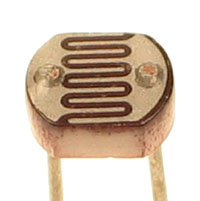
thanks for all of the replies guys!! I would like the LED to light up once light hits the photocell. I'm not sure waht "CdS" means but it looks exactly like this one:
Photocell.jpg

I got a pack of a few sizes of these.

I will have all components housed in the project box except for the photocell (which will be wired to the place I am observing light. When the lights come on in that spot I would like the LED to light up(that is in the project box). Hopefully that helps?
 
That's a light dependent resistor (it has tons of other names also), I'd think the best solution would be the link i provided in my post above.
 
but I think the diagram on that link just shows a general diagram of how to approach it. I'm looking for specifics so I can purchase the right resistors.
 
Generally, you'd use a 1Kohm resistor as the "preset resistor" Using V=IR and supplying 20MA to the LED at around 2.2V we get around 340 ohms for the resistor hooked up to the LED
 
http://img.photobucket.com/albums/v62/jfkfhhfj/ldr.jpg

There's a little something i put together, Can you tell i'm a prospective CE student with too much time on his hands? :D

All i used was a LDR i had, 1Kohm precision resistor and a 330 ohm resistor for the LED and a low power transistor.

The "sensitivity" of the circuit is determined by the ratio of the resistance of the LDR and the resistor it is in series with. If their resistances are radially differnt, the circuit will only switch on a large difference in light. You can substitute the resistor the LDR is in series with for a potentiometer, to gain the ability to "select" the sensitivity.

I hope you have luck with your project, there are tons of electronics geeks willing to give you a hand
 
@Jfkfhhfj thanks for those pictures! I'm trying to make sense of them (sorry very noob). You dont by chance have a schematic of that do you?

@mtrupi ya I had seen that one too! It was somewhat what I initially followed, however I used an LED versus a 12V siren and thought all the voltages would therefore be different.
 
The schematic is the exactly the same as the one i linked to, Except i'm using one transistor instead of two.
 
@mtrupi ya I had seen that one too! It was somewhat what I initially followed, however I used an LED versus a 12V siren and thought all the voltages would therefore be different.

I was wanting to show a way the opposite behavior would be achieved. LED on when the lights go out. The circuit for an LED would be a little different but basically you're needing an inversion from the other design.
 
great! thanks for all the help guys! I'll give it a try once I get a chance to pickup the rest of the parts.
 
Back
Top