[another] lcd mod question

Frustrated

n00b
Joined
May 29, 2005
Messages
17
Ive been searching for quite a while, and ive looked through your faq on lcds. I currently have a perfectly working lcd screen, which im hoping to attach to my pc to use as a temperature reader, etc. However, after extensive research, i have come up with nothing.

Ive uploaded a few images of the lcd screen:
d5ebc1e7.jpg

0f54bf9e.jpg

fbf80732.jpg


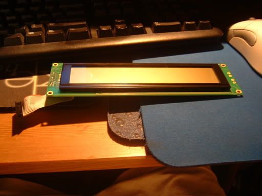
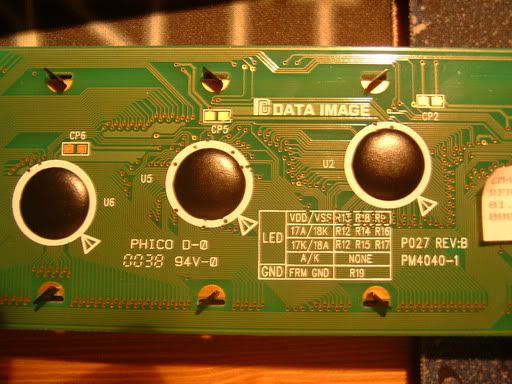
all ideas are welcome. THANKS.
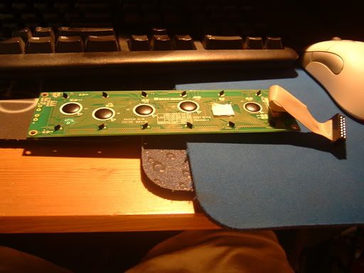
 
Read what it says on the sticker covering that square shaped IC. In particular, read off the part that starts with "CM-".
 
You can find data sheets for the CM404000 at the DataImage website. This part has a parallel interface, so you'll have to do a bit of work to interface it to your PC.
 
are there any ideas as of HOW im going to connect this with my pc? Im a fairly new to all of this.
 
Okay, I'm 99% sure it uses the Sitronix ST7066 controller/driver IC, based on this datasheet from Data Image,

http://dataimagelcd.com/product/cm/pdf/CM400400FRNNA-01.pdf

Fortunately, the Sitronix ST7066 is functionally equivalent to the well-supported and popular Hitachi HD44780 controller/driver IC. You should be able to use the pin configuation on this page to connect to your PC's parallel port:

http://dataimagelcd.com/product/cm/doc/cm400400.htm

This image describes the parallel port to LCD interfacing:

http://www.beyondlogic.org/parlcd/parlcd.gif

Note that your LCD has two enables, which you should just tie together.

Let me know if you have any further questions.
 
i was looking through some other lcd mod how to's. Could i use a printer cable to do all of this?
 
Sure you can!
Printer cable = Parallel cable :)
Since the parallel would only be used for data transmission, you'd have to either use USB or a molex for power.
 
now that i have the data cables plugged in, i need to do the power. How am i do power this? Im a little bit confused as of how i use a usb to power it...explain?

can i use this wire [below] ? if yes, how?

5a2c6863.jpg
 
okay, so i took a look at your webpage, and got this:


PIN# SIGNAL
1 +5
3 +Data
2 -Data
4 GND

i know that i use pin 1 for powr, and 4 for ground, and what do the other two do?


also, on my data sheet ( http://dataimagelcd.com/product/cm/doc/cm400400.htm) i found the following and im stumped on what it means:

"12--VO-- LCD Drive Voltage"
"15--e2-- enable singal 2"
 
With regards to your USB question, the other two pins are for the differential data lines used for data transfer. You can ignore them and just use power and ground (pins 1 and 4).

VO on your LCD can be connected as shown on the schematic already posted:

http://www.beyondlogic.org/parlcd/parlcd.gif

and E2 can be tied to E1, and together treated as pin E in the schematic I just linked to.
 
Make sure power is going through the USB port?

As long as it's from a powered USB port (i.e. any USB port connected to the motherboard directly), you will get power regardless of whether there is a proper USB device connected or not.
 
xonik said:
Make sure power is going through the USB port?

As long as it's from a powered USB port (i.e. any USB port connected to the motherboard directly), you will get power regardless of whether there is a proper USB device connected or not.

no, i want to make sure there is power going through the lcd.
 
Use a multimeter and measure the potential between the VO and GND pins. It should be 5 V. Alternatively, you could apply power to the LEDA, and connect LEDK to ground, and the backlight should light up.
 
Frustrated said:
no, i want to make sure there is power going through the lcd.
the LCD will have a testpatern even if there is no data going to it. every odd line should have solid bars across it. this meens that power is good.
 
Well, i got what im SUPPOSED to be doing now, however, im still stumped as of which wires on the parallel port wire should be going to my lcd?
 
Back
Top