It has been nearly a year and a half since I finished my last project "Troy's Arcade" and it's time for a sequel. I had initially planned on building another MAME with a trackball, spinner, 4-way stick and light guns, but then I saw an article at metku.net covering a pinball build and immediately all other plans were abandoned.
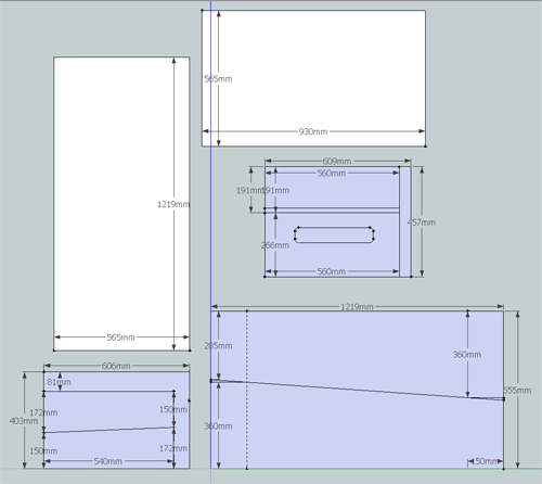
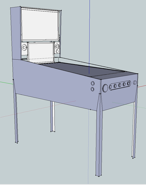
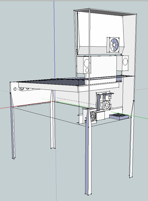
Before I ever plunked a quarter into any video game as a kid I had already played a fair amount of pinball, but it wasn't until I found a Williams Whirlwind machine in the early 90's that I truly knew how much I loved playing. Based off a Williams wide body machine my Google Sketchup design is now final and all the hardware/parts needed for the build are here.
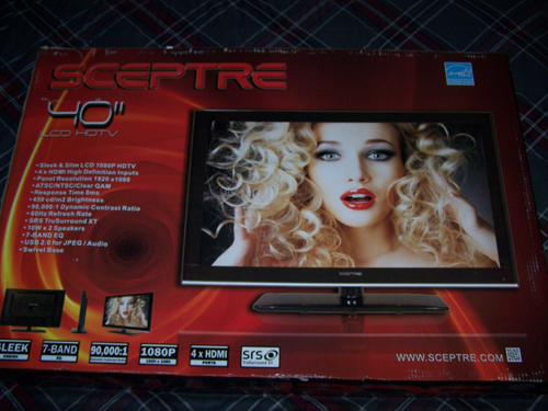
Sceptre 40" Class LCD 1080p 60Hz HDTV, X405BV-FHD, 1920 X 1080 @60hz, 16:9 Wide Screen, 8 ms, 400 (W) x 200 (H), Screen size is 35" wide x 20" high (40" diagonal)
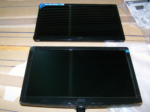
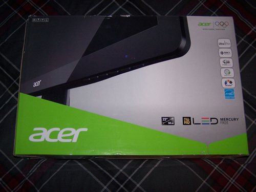
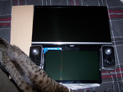
Acer S230HL Bmii 23" Class Widescreen LED Backlit Monitor - 1920 x 1080, 16:9, 100000000:1 Dynamic, 1000:1 Native, 60Hz, 5ms, HDMI, VGA
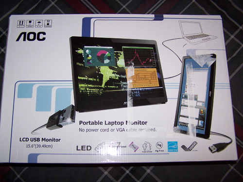
AOC e1649Fwu 16" Class Ultra Slim USB Portable LED Backlit Monitor - 1366 x 768, 16:9, 500:1 Native, 60Hz, 16ms, U-Slim
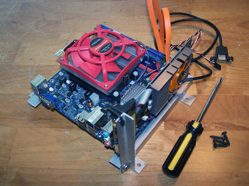
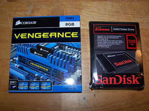
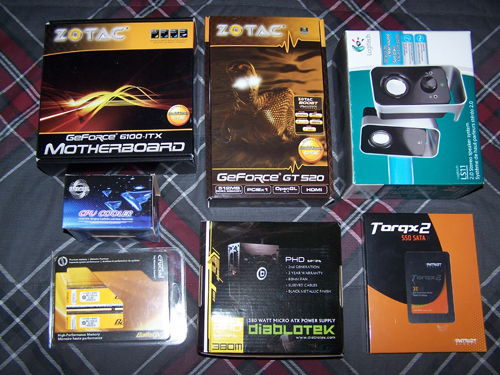
Below is a list of the hardware I will be using for this build followed by a picture of it all...
ZOTAC GF6100-E-E AM3 / AM2+ / AM2 NVIDIA nForce 430 MCP Mini ITX AMD Motherboard
ZOTAC ZT-50608-10L GeForce GT 520 (Fermi) 512MB 64-bit DDR3 PCI Express x1 HDCP Ready Low Profile Ready Video Card
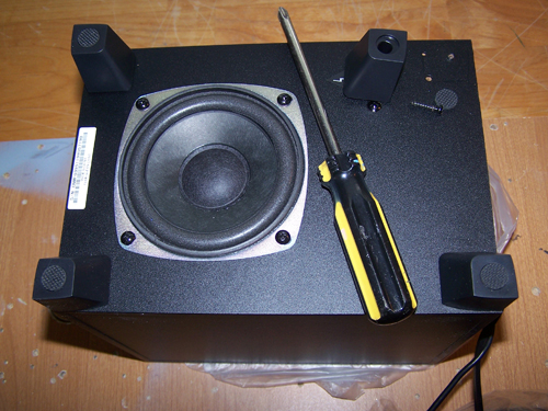
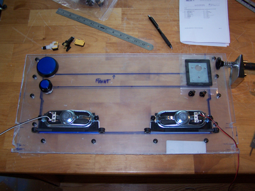
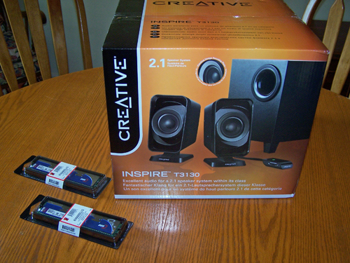
Logitech LS11 Stereo Speakers - 2.0 Channels, 3 Watts RMS, 2" high-excursion metallic drivers
Patriot PT232GS25SSDR Torqx 2 32GB Solid State Drive - 32GB, SATA I/II
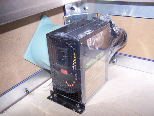
Diablotek PHD Series PHD380M 380W Micro ATX Power Supply
Crucial Ballistix 2GB (2 x 1GB) 240-Pin DDR2 SDRAM DDR2 800 (PC2 6400) Dual Channel Kit Desktop Memory Model BL2KIT12864AA804
AMD Athlon 64X2 (ADO4000IAA5DD) CPU 2.1GHZ
EVERCOOL EC-NK804A-925EP 92mm Ever Lubricate CPU Cooler for AM2 and AM3 Series
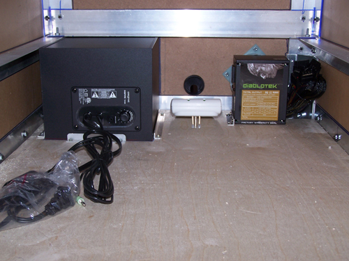
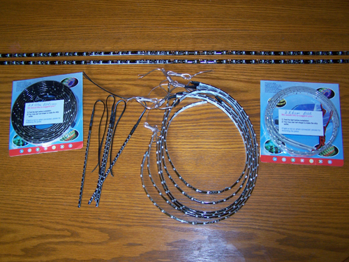
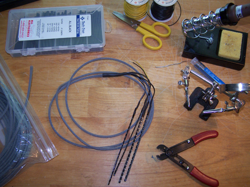
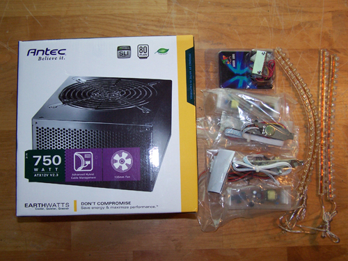
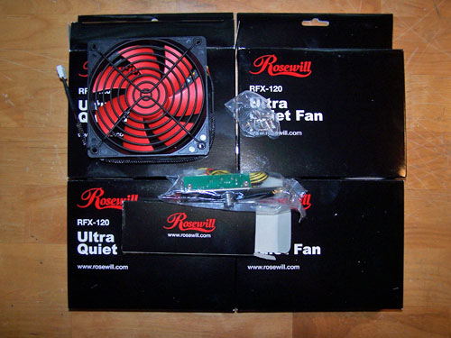
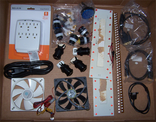
Below is a Belkin 6-outlet surge protector, four pushbuttons and six lighted pushbuttons, two 120mm fans (one speed controlled), two types of red LED lighting, an HDMI and a DVI to HDMI cable, a USB internal to external cable and a 6" extension cord/power cable.
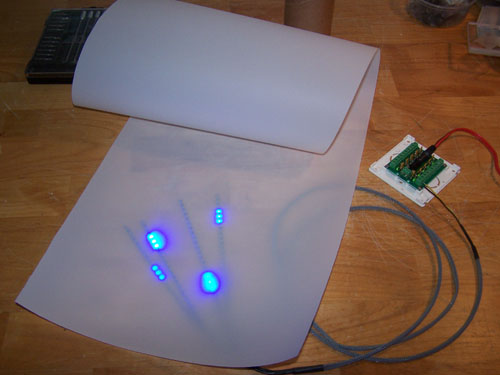
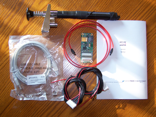
This next part took a total of 51 days from the day I ordered it to receive it, so if you plan on building your own pinball machine make sure to order the Mot-Ion Adapter & Digital Plunger Kit at least two months before you know you want it.
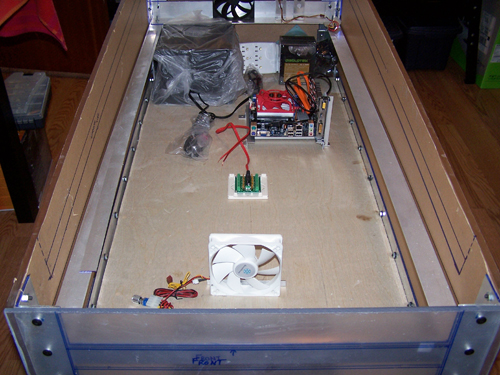
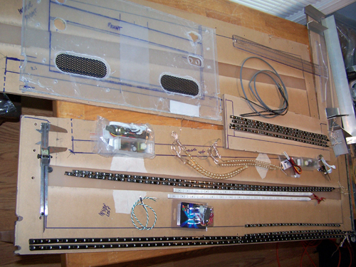
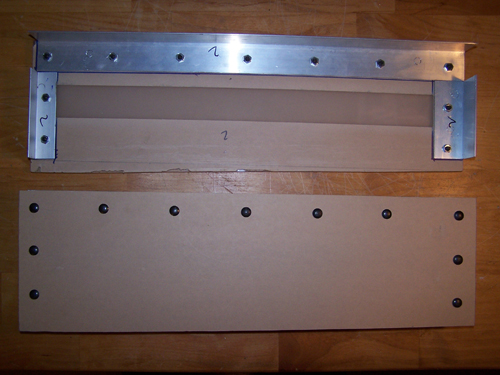
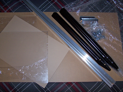
Below is what will make up most of the enclosure, it consists of one Acrylic Plexiglass Sheet Clear 3/8" x 23.7/8" x 15.7/8" and one 3/8"x 48" x 25.7/8" sheet, two sheets of OPTIX acrylic 3/16" x 18" x 24", three 8" x 1 1/2" lengths of corner Alum-Angle, four black 28" Williams pinball table legs and the mounting brackets, bolts and four leg levelers that go with them.
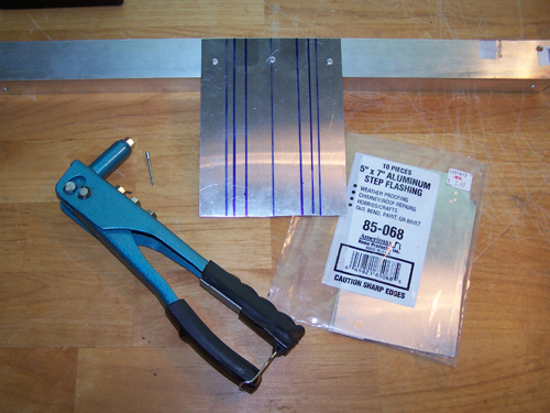
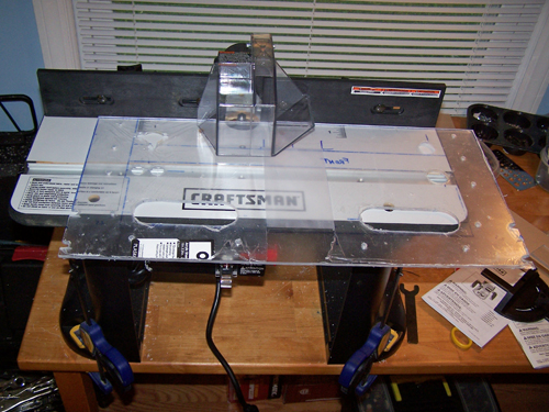
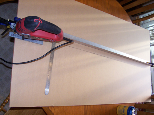
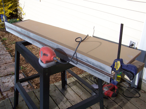
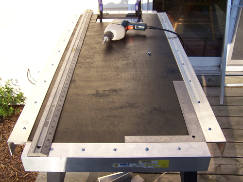
I cut one of the 8 foot lengths of Alum-Angle in half and clamped it onto the 48"x26" sheet of 3/8" thick acrylic to use as a guide for the jigsaw.
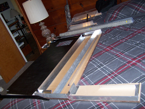
It is difficult to get an exactly straight even cut, so the side panels will be double sided taped together in preparation for sanding. The two four foot sections of Alum-Angle will be taped onto the edges as guides to keep my sanding even and let me know when to stop.
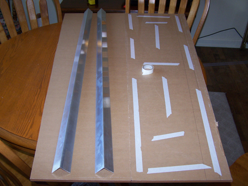
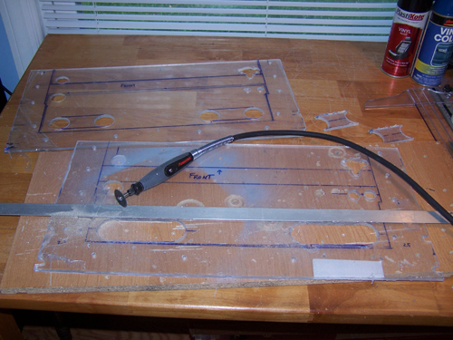
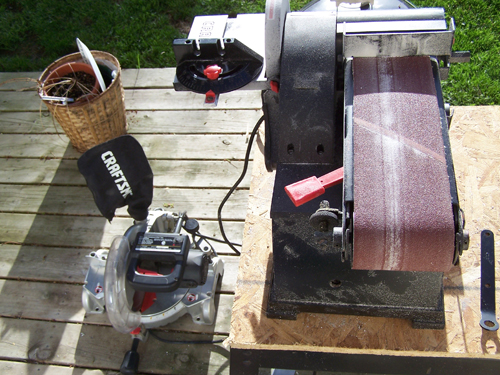
Forever later and it's sanded pretty even, below shows the taped and clamped Alum-Angle / Acrylic and Mouse sander.
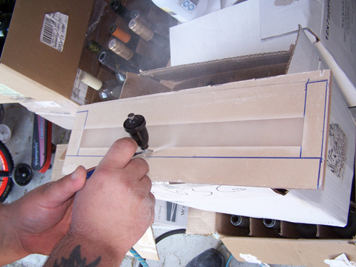
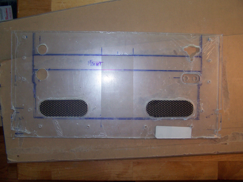
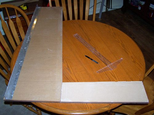
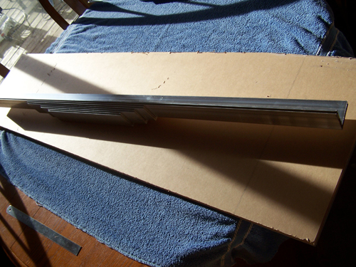
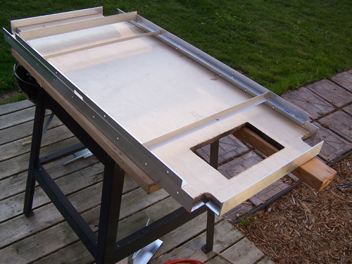
I cut both sides of the of the marquee and sanded them like I did to the side panels. It still needs a little work, but the following picture shows just how massive this thing is.
Here is the back of the 40" LCD, it will have to be removed to allow for accurate measurement of the LCD screen.
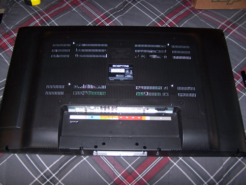
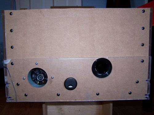
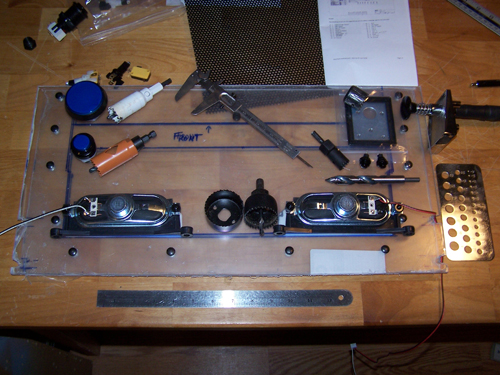
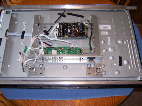
Screws removed and back cover off - the speakers, IR receiver and TV side controls will all be removed and then relocated inside the body of the pinball table. While I was looking at the back of the screen I noticed that my Sceptre LCD contains parts stamped Samsung.
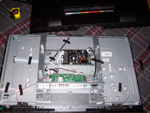
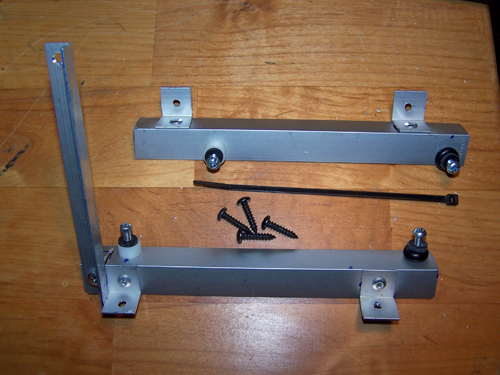
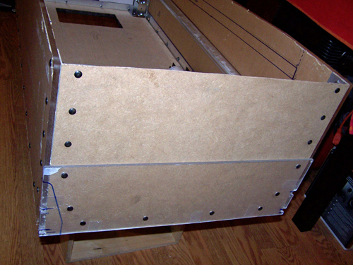
Ok, in this next picture all the stuff I mentioned removing above has been, plus you can see where I cut away any steel bits that were in the way. I also cut two lengths of Alum-angle that will run up the edges and serve as the mounting rails for the screen.
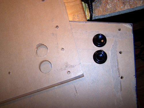
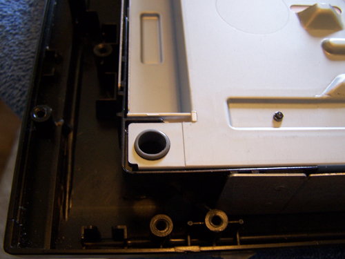
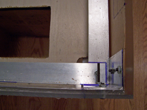
There is a rubber grommet lined hole like this in each corner of the screen, all four are ready made to be the points at which the side rails attach to the screen.
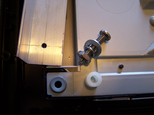
I bought four nylon spacers and they fit snug against the rubber grommets inside the holes, the bolt, washer, lock washer, nut combo will hold the rails down.
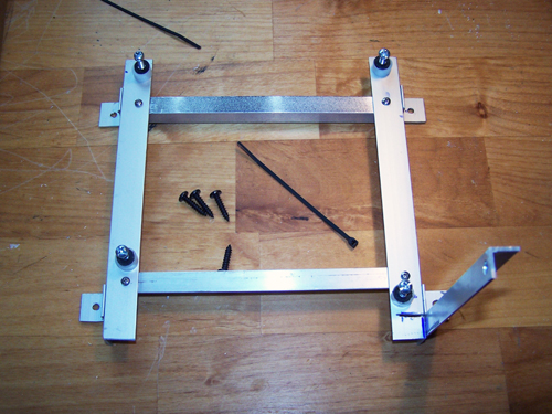
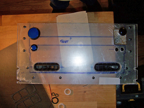
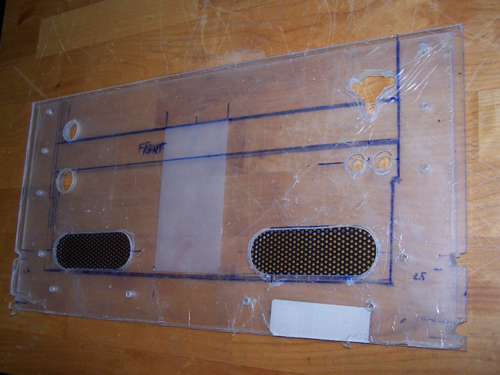
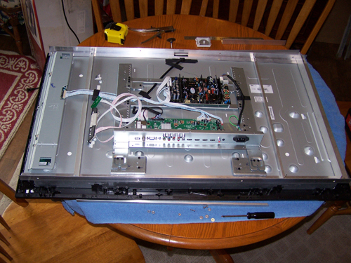
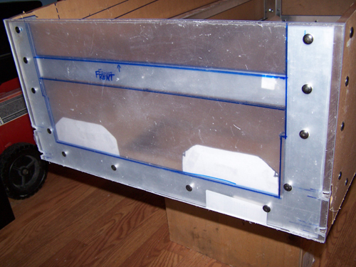
I cut a corner section out of the middle of one of the side rails to allow a ribbon cable to pass through. The side rails were mounted and then marked for the placement of three Alum-Angle brace rails, that were then then measured, cut and installed. Below shows the modified 40" LCD screen all finished up and ready to mount.
Stay Tuned... More To Come.
Before I ever plunked a quarter into any video game as a kid I had already played a fair amount of pinball, but it wasn't until I found a Williams Whirlwind machine in the early 90's that I truly knew how much I loved playing. Based off a Williams wide body machine my Google Sketchup design is now final and all the hardware/parts needed for the build are here.
Sceptre 40" Class LCD 1080p 60Hz HDTV, X405BV-FHD, 1920 X 1080 @60hz, 16:9 Wide Screen, 8 ms, 400 (W) x 200 (H), Screen size is 35" wide x 20" high (40" diagonal)
Acer S230HL Bmii 23" Class Widescreen LED Backlit Monitor - 1920 x 1080, 16:9, 100000000:1 Dynamic, 1000:1 Native, 60Hz, 5ms, HDMI, VGA
AOC e1649Fwu 16" Class Ultra Slim USB Portable LED Backlit Monitor - 1366 x 768, 16:9, 500:1 Native, 60Hz, 16ms, U-Slim
Below is a list of the hardware I will be using for this build followed by a picture of it all...
ZOTAC GF6100-E-E AM3 / AM2+ / AM2 NVIDIA nForce 430 MCP Mini ITX AMD Motherboard
ZOTAC ZT-50608-10L GeForce GT 520 (Fermi) 512MB 64-bit DDR3 PCI Express x1 HDCP Ready Low Profile Ready Video Card
Logitech LS11 Stereo Speakers - 2.0 Channels, 3 Watts RMS, 2" high-excursion metallic drivers
Patriot PT232GS25SSDR Torqx 2 32GB Solid State Drive - 32GB, SATA I/II
Diablotek PHD Series PHD380M 380W Micro ATX Power Supply
Crucial Ballistix 2GB (2 x 1GB) 240-Pin DDR2 SDRAM DDR2 800 (PC2 6400) Dual Channel Kit Desktop Memory Model BL2KIT12864AA804
AMD Athlon 64X2 (ADO4000IAA5DD) CPU 2.1GHZ
EVERCOOL EC-NK804A-925EP 92mm Ever Lubricate CPU Cooler for AM2 and AM3 Series
Below is a Belkin 6-outlet surge protector, four pushbuttons and six lighted pushbuttons, two 120mm fans (one speed controlled), two types of red LED lighting, an HDMI and a DVI to HDMI cable, a USB internal to external cable and a 6" extension cord/power cable.
This next part took a total of 51 days from the day I ordered it to receive it, so if you plan on building your own pinball machine make sure to order the Mot-Ion Adapter & Digital Plunger Kit at least two months before you know you want it.
Below is what will make up most of the enclosure, it consists of one Acrylic Plexiglass Sheet Clear 3/8" x 23.7/8" x 15.7/8" and one 3/8"x 48" x 25.7/8" sheet, two sheets of OPTIX acrylic 3/16" x 18" x 24", three 8" x 1 1/2" lengths of corner Alum-Angle, four black 28" Williams pinball table legs and the mounting brackets, bolts and four leg levelers that go with them.
I cut one of the 8 foot lengths of Alum-Angle in half and clamped it onto the 48"x26" sheet of 3/8" thick acrylic to use as a guide for the jigsaw.
It is difficult to get an exactly straight even cut, so the side panels will be double sided taped together in preparation for sanding. The two four foot sections of Alum-Angle will be taped onto the edges as guides to keep my sanding even and let me know when to stop.
Forever later and it's sanded pretty even, below shows the taped and clamped Alum-Angle / Acrylic and Mouse sander.
I cut both sides of the of the marquee and sanded them like I did to the side panels. It still needs a little work, but the following picture shows just how massive this thing is.
Here is the back of the 40" LCD, it will have to be removed to allow for accurate measurement of the LCD screen.
Screws removed and back cover off - the speakers, IR receiver and TV side controls will all be removed and then relocated inside the body of the pinball table. While I was looking at the back of the screen I noticed that my Sceptre LCD contains parts stamped Samsung.
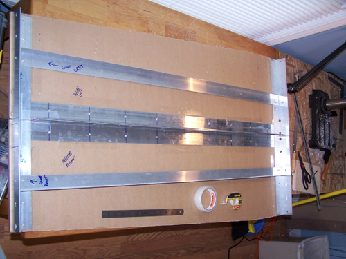
Ok, in this next picture all the stuff I mentioned removing above has been, plus you can see where I cut away any steel bits that were in the way. I also cut two lengths of Alum-angle that will run up the edges and serve as the mounting rails for the screen.
There is a rubber grommet lined hole like this in each corner of the screen, all four are ready made to be the points at which the side rails attach to the screen.
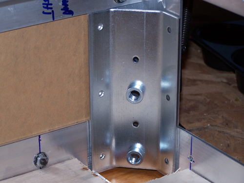
I bought four nylon spacers and they fit snug against the rubber grommets inside the holes, the bolt, washer, lock washer, nut combo will hold the rails down.
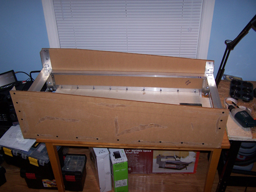
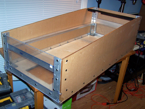
I cut a corner section out of the middle of one of the side rails to allow a ribbon cable to pass through. The side rails were mounted and then marked for the placement of three Alum-Angle brace rails, that were then then measured, cut and installed. Below shows the modified 40" LCD screen all finished up and ready to mount.
Stay Tuned... More To Come.
")