computergeek485
2[H]4U
- Joined
- Jun 20, 2008
- Messages
- 2,389
looks good, congrats on making it to the front page of hardocp
Follow along with the video below to see how to install our site as a web app on your home screen.
Note: This feature may not be available in some browsers.
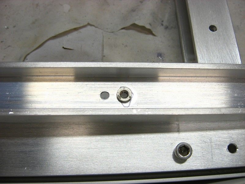
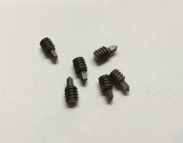
Spotswood, where did you get PEM cinch nuts? I'm afraid if I go to the hardware store and ask, they'll think I'm crazy and I'll just go home empty handed.
Also, did you use rivets to attach some of the aluminum together?
Very cool.
Is there a reason you didn't use pop rivets to put the case together?
Stinky

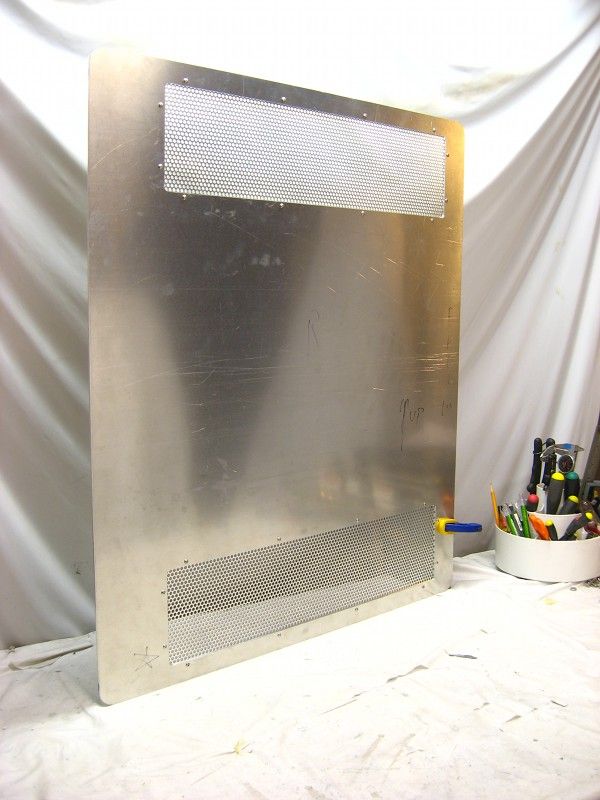
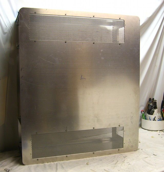
Very nice build! The aluminum will look top notch.
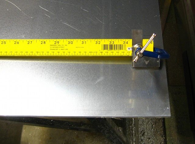
I've been wondering about my future projects, and one of the issues is main dimensions. Where were you able to find proper actual dimensions for all of the different specs? (ie. 5.25" drive hole spacing, ATX mobo hole spacing and fans) Is there a database or library with this kind of information?
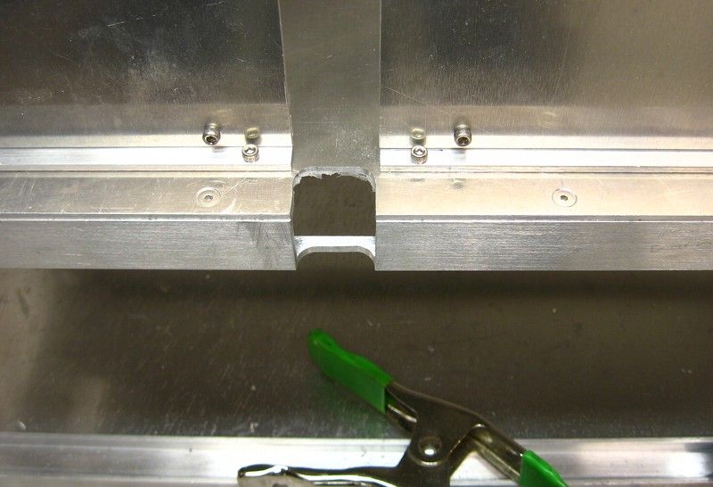
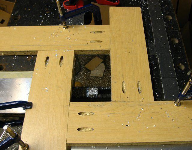
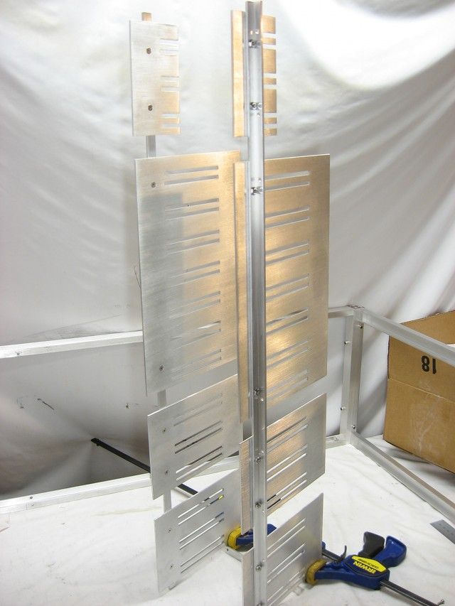
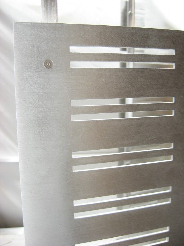
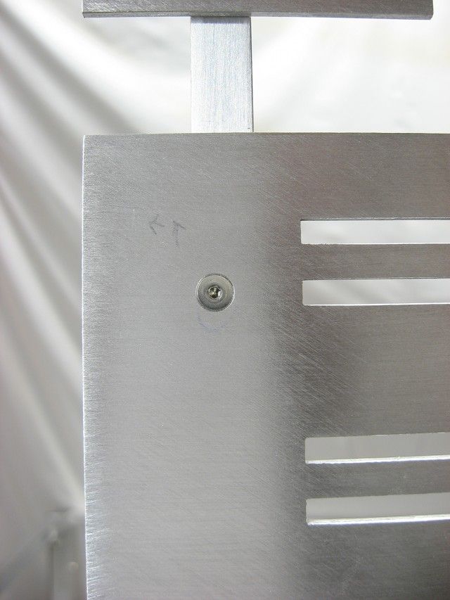
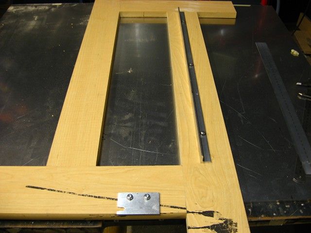
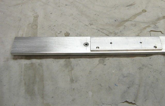
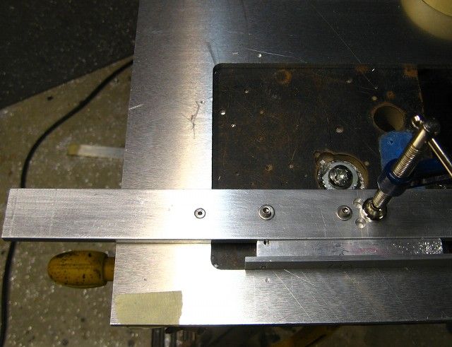
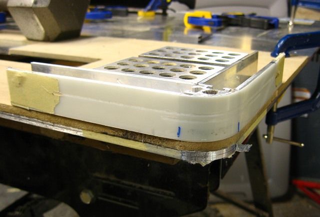
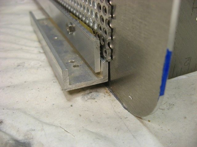
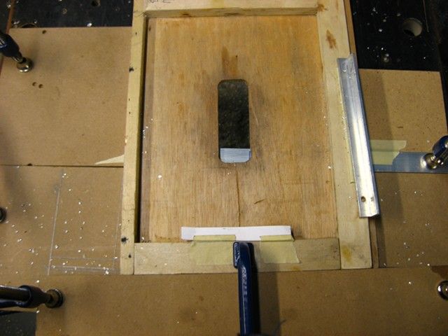
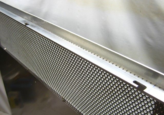
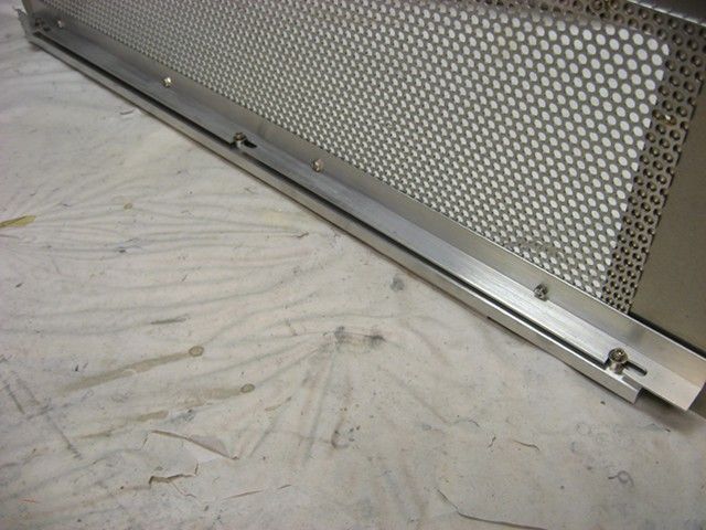
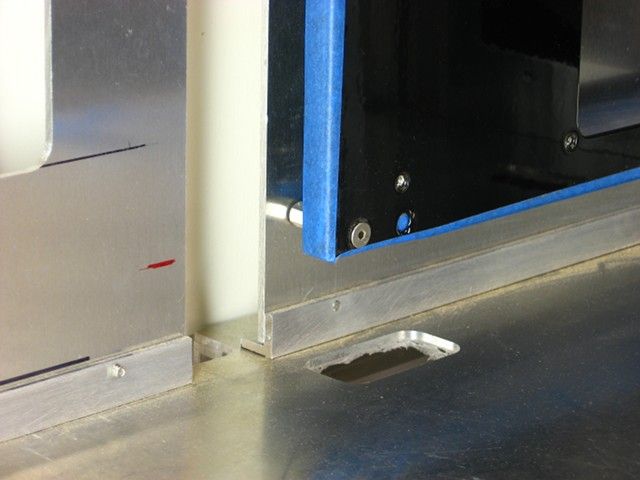
The 5.25-inch drive bay rails:
Question:
Why did you square the corners of the 5.25-inch drive bay rails? Is the router bit a different diameter? Is it purely aesthetics, or is there some other purpose? I think it would be much easier to let the router do the work for you! Just saying...
Note: I don't mean to offend you via this post, I'm just curious.
Love your work, keep it up!
Probably ten times more than anything you can get from silverstone or lian-li.
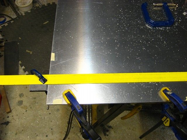
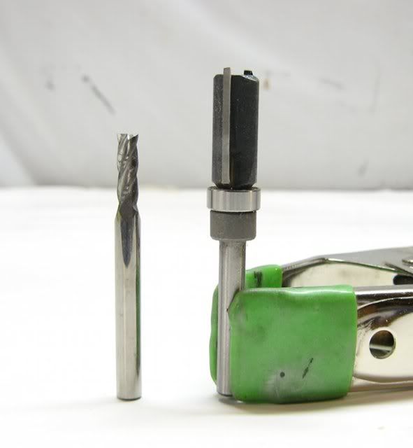
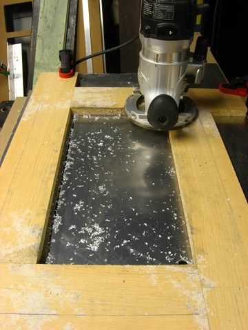
I'm thinking of making a new aluminium front panel for my case much like yours. I'm most worried about getting the cuts straight and using a router as you have seems to be the way to go. Could you give more details on the router you used and the bits? Would a dremel with the router attachment and aluminium router bits do the job? Finally, did you have to spray coolant onto the bit whilst cutting?


dude...3 letters for you
C N C