Homemade 3D Printed Water Cooling System(s) and Stuff

Joined
Oct 23, 2018
Messages
1,015
This thread will serve as the worklog for a bit of a water cooling journey. It will cover a simple 1000D and grow into a rack mounted external cooler serving several systems concurrently. Since this first post is after some progress has already been made, it will probably be some time before the next major update. But anyway, here we go....

My end goal with this is to have a rack mounted exeternal cooler that serves a number of systems that are on that rack. As systems age, they rapidly become too low-valued to even justify selling. At the same time, on-demand distributed computing projects (like Otoy's RNDR) make it so that there is still some value in keeping those systems online. Rather than eating the value loss every time I do a new build, what if I just kept the older ones online? Rather than ending up with a room overflowing with old stuff, what if I began doing all of my builds in rackmount ATX chassis and condensed everything into a single rack? Rather than hearing all of the associated fans recirculate hot air from the room, what if I ran them through a water cooler that was on the rack and fed with chilled air from a dedicated air conditioning unit? Well, here we are.
  1. Yes, I know that I could put a radiator door on the rack and use that to chill the air going into the machines. By a huge margin, this would be the easiest AND cheapest way to proceed.
  2. Yes, I know that this is common practice in datacenters.
  3. Yes, I know I'm an idiot. This is an important point to keep in mind with everything that I post.
I am an experienced mechanical engineer and thus I know how to build stuff plus have a network for fabricating various bits like the the sheetmetal for a chassis. But do you see point #3 above? I think I could probably 3D print a substantial portion of this setup. Is that the easiest option? No. Is that the cheapest option? Also no.

I guess this project will be broken into a few different core phases/milestones:
 
Last edited:

Phase 0 - Project Scoping and High Level Topology​

I guess at the highest level, there are two main areas of activity here:
  1. Connect the AC unit to stuff
  2. Make it so that the stuff can be connected to the AC unit
It is from these two items that everything else is derived.

#1 is fairly straightforward. It is a somewhat ordinary window-mount AC unit with a wide and low profile output vent fed by an ordinary blower fan. This fan isn't super high flow and, despite being a blower, it isn't super high pressure either. I will try to minimize flow restriction by massively oversizing the ducting, allowing for the potential use of a booster stage, and providing internal flow guides where my eyeball estimates arbitrarily decide they might be useful*. Given the fairly short piping run, I think a 6" ID for the ducting is a reasonable target. The collector will, of course, be smaller than that, and the expansion area that mates with the PC gear will be larger, but 6" ID seems reasonable for the ducting that transports the air from AC to PC (we can call this an AC-PC Converter if you want). I may end up needing to print adapters in order to utilize standard ducting though.

*I would love to run some CFD on this, but given all of the design work plus a new puppy arriving soon, I don't have time to learn a new package well enough to get useful insights from the analysis. I'm planning to open source all of this, so maybe someone else would like to take that on?

Circling back to the scoping statement, it follows that the stuff in #2 will depend somewhat on the capacity of the AC unit in #1.
  • The AC unit is rated for 12k BTU/hr, which works out to roughly 3500w of power that it will transport from inside of the room to outside.
  • The circuit the rack is on is currently 230V @ 20A (4600w max), so it supports generating about 3500w of heat @ 75% load.
  • This feels like a surprisingly nice match given that I'm just working from a rack and an AC unit which I already owned.
  • Given the above, I have a soft goal of having the radiator box be capable of supporting about 7kW of load so that it can be run at a low duty cycle and still be capable of supporting a fan failure or five without issue.
  • It would be good if the cooler didn't require the AC unit to be running. I'd prefer if the cooler worked fine using 68F/20C air and worked betterwhen the AC unit was running.
    • Having the AC unit be fully optional is a stretch goal, but we'll see how this all pans out
    • The reality of life in an old apartment is that the room will get heated by my 90F-loving neighbors in the winter as well as take considerable thermal input from the sun in the summer. This means the AC unit is an unavoidable requirement in order to simply keep the room below 75F for most of the year. Ducting its output directly into the equipment, however, will help ensure that it runs at maximum efficiency when it is running.
    • I'll also add that a window duct that simply pulls in outside air is in-scope for the cooler months.
With a 7kW target, next up is getting some idea of just how much radiator I can fit. In some ways, the sky is the limit. In others, the limit is just above ground level (or at least feels that way once the CAD gets started). The rack is a standard 19" rack, so that sets up some guardrails.
  • Radiator dimensions:
    • The biggest standard PC radiator that fits through the 18" wide opening on a standard 19" rack comes down to how you define "biggest"
      • Going by max width alone, 360mm is the biggest (3x120mm fans)
      • Going by max area, 400mm is the biggest (2x200mm fans)
      • Changing to a 23" telecom rack would mean 420mm rads could fit, but at this point a rack change is out of scope
    • Fan airflow capability is all over the map even without accounting for pressure
      • Noctua says their NF-A12 INDUSTRIALPPC-3000 will push 186.7 m^3/hr
      • Noctua says their NF-A14 INDUSTRIALPPC-3000 will push 269.3 m^3/hr
      • Noctua says their NF-A20 PWM will push 146.7 m^3/hr
    • A quick check of static pressure eliminates the NF-A20 from consideration. At 1.08 mmH2O, it would get completely choked out by a radiator
    • If I multiply the volumetric flow rate by radiator area (approximated by calling it the same as the nominal square area of the fan)
      • 360mm rad comes out to ~8 million
      • 280mm rad comes out to ~10.5 million
    • Based on the above, I think 280mm will be the choice. A side benefit is that this gives extra width for routing cables and tubing, placing fan controllers and sensors, and possibly even mounting slides for aiding in service.
Now that I've narrowed down the radiator size to 280mm, how many of them am I going to need?
  • I don't have a great calculator for giving ballpark performance estimates on complex systems with multiple radiators. I do, however, have the incredible and timeless ExtremeRigs.net radiator compendium of single 360mm radiator testing to help guide me
    • Given how rough my back of the envelope estimates are going to be here, a critical assumption is going to be that the air supply is going to be unlimited in terms of both volumetric flow rate and pressure. I'm planning to use Noctua's most capable fans in this install, and those are rated for both significantly more volume and significantly more pressure than what was used by ExtremeRigs.net, so I don't think this will lead to any big surprises down the road.
    • I'm going to focus on the 1850rpm test results. I will be using 3000rpm fans, so there should still be plenty of available capacity if needed. Not all RPM are created equal, but, again, I'm using fans with significantly higher ratings and thus their RPM should be more equal than others. Going to a better control would require more time and expense for testing than I'm looking to invest in this already objectively stupid hobby project.
    • Similarly, I will focus on the 1.0gpm coolant flow rates. I'm trying to avoid paralysis by analysis. I have to start somewhere, and this seems like an ok place to be.
      • This may prove to be a regrettable decision, but that's all part of the intra-scoping risk analysis
      • As a sanity check, let's check out the flow rate for the Aquacomputer D5 NEXT
        • Spec page on ModMyMods shows 1500L/H. This is presumed to be at 100% of capability but is measured at an unknown head pressure. Still, it's a starting point
        • Converting to gpm in order to align with the radiator test dataset, we get approx 6.6gpm.
        • If the radiator bank gets run as three parallel sets, this would allow for 2.2gpm per set at full pump load or 1.1gpm at half load.
        • This style of pump can get choked by high flow resistance. That's bad. Running multiple (or many) pumps of this style in the same cooling loop, however, is both easy and predictable in both series and parallel configurations.
        • As a result, I consider this risk to be suitably identified and with suitable mitigations also identified.
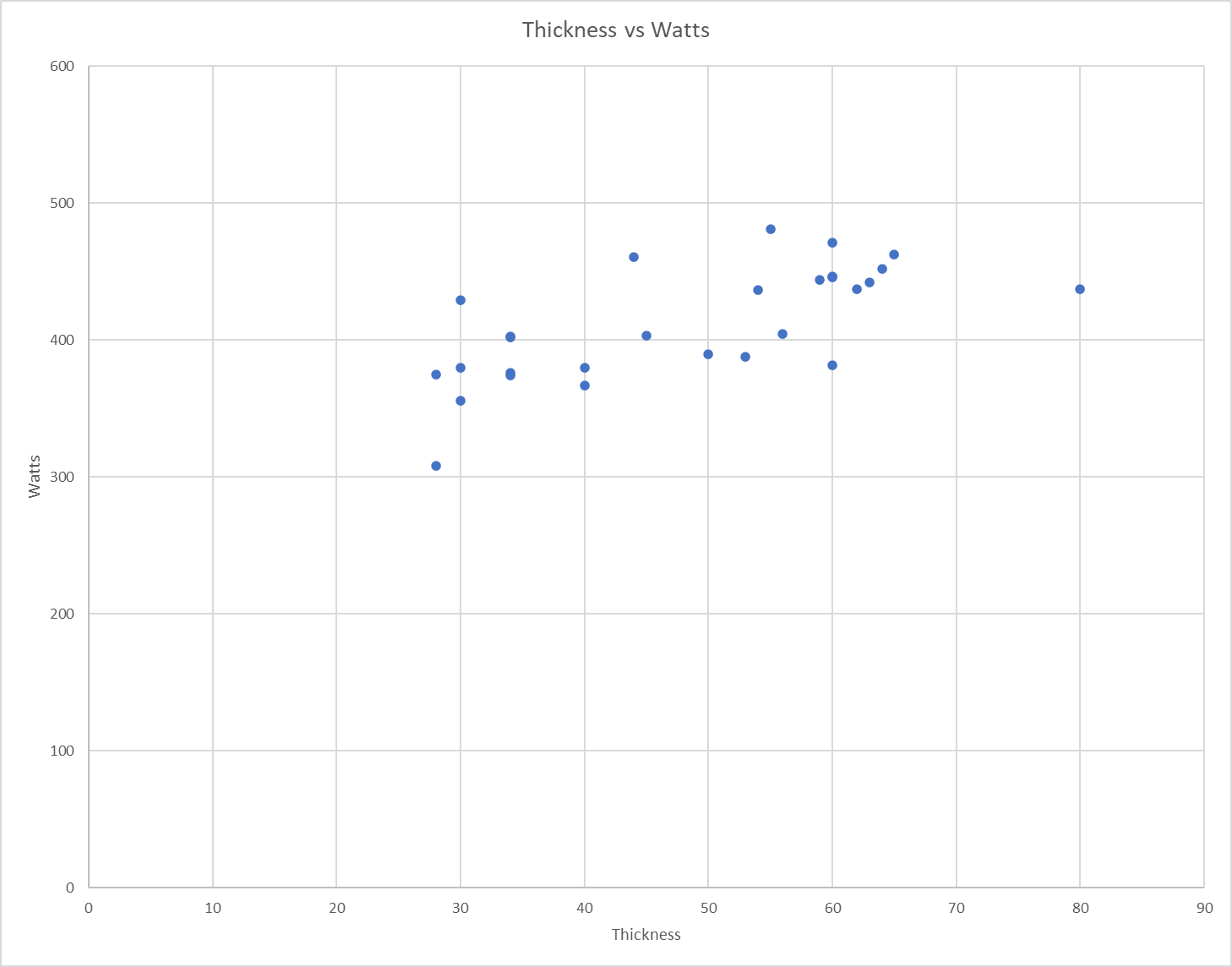
  • Plotting the results as exterior radiator thickness versus watts per 10C delta T and isolating for just traditional U-flow, I get this:
    • 1698614825828.png
    • Note that this is the external dims of the radiator rather than core thickness. I need to fit these radiator into an existing space, so the full thickness of the radiator is what matters to me rather than the thickness of just the core. If I were doing a core efficiency study, the core thickness would matter. For this, what matters is the component-levle efficiency. A brilliantly efficient 10mm core isn't useful to me if that means a 200mm thick component.
    • Eyeballing that plot, there don't seem to be any clear groupings. There is a rough trend towards thicker being able to dissipate more watts (not a big surprise), but there isn't a huge spread. At 30mm, we're looking at around 350W and at 60mm, we're looking at around 450W.
    • Based on this data, I'll select the specific radiator model based on a fungible combination of parts availability, price, watts per 10C delta T, and a rough assumption that thicker means more mass.
    • Using the volume-surface combo I mentioned above wherein a 280mm radiator could be dissipating 30% more heat at max fan output, I can guesstimate that I would need between 6 and 8 radiators at 10C Delta T for 3500W capacity at around 50% fan capacity.
  • That's a lot of radiators to have to fit. I don't have a hard limit for how many U of rack space this can take up, but there's still value in not going crazy here (I realize that this is FAR too late to be considering the sanity of the solution). Still, what if we explore our assumptions a bit more?
    • The radiator count is based on a 10C delta T. In a 20C room, this would mean 30C coolant.
    • Based on [admittedly annecdotal] experience, running coolant at 40C is perfectly fine for high reliability computation. This coolant temp keeps both GPU and CPU temps far below (on the order of 30C) where the respective components will throttle, and even further below the point where components may see a measurable reduction in stability and/or reliability.
    • 50C coolant temps are where I would be concerned about cooling system function. 55C is where the very first cooling system component operational limits are encountered.
    • With 20C input air and 40C coolant, can we simply double the numbers from the ExtremeRigs testing? If we were sending a man to the moon, absolutely not. For a hobby project, however, that's a reasonably safe guideline. Again, based on experience, other perculiarilities of the specific system implementation will have a much more significant impact than the error in this approximation.
    • Phew! It's looking like 6x280mm radiators just might get me to where I want to be even with a double-double safety margin.
  • One additional consideration is where the ports are on the radiator.
    • Having ports on both sets of opposite faces on the end tank would make routing easier.
    • Having ports on all three sides of the end tank would make routing easiest.
  • TL;DR:
    • I'm going to need 6x 280mm rads
    • TitanRig is currently having a sale on Alphacool
    • The 280x45mm Alphacool V1 has ports on all three sides of the end tank but only three are showing as in stock.
    • The 280x45mm Alphacool V2 has ports on opposite sides of the end tank but at least 6 are showing as in stock.
    • [adds V2 to cart]
    • [checks out]
Time to start designing stuff.
 

Phase 1 - Connect the Existing AC Unit to the 1000D​

Alright, time to figure out just how deep this rabbit hole might be. What could possibly go wrong?

Unit snob warning: I'm fluent in inch and metric and will freely swap between them during this process. When my measurements look like they're close to coming out to an even number in mm or inches, I will round to that unit because that's probably what the original engineer was intending.

First step is to take some basic measurements of the AC vent. I have my trusty [calibrated] Mitutoyo CD-8"CSX 8" digital caliper for measurements up to 8", my handy-dandy DigiKey ruler for measurements up to 12", and my #America Stanley measuring tape for the rest.

The air conditioner is a 12k BTU Midea U-shape unit. This thing was insanely quiet when it was new. It was difficult to tell if the compressor was running even when placing my hand directly on it. I'm going to mount on the outer faces of the unit, so the inner vent dimensions don't matter a ton to me. The tape says the unit is 19.75" wide and the vent is effectively the full width. The vent actually has a basic 3D profile, as if the top edge of the unit has been cut off at an angle. Using the ruler as a straight edge reference, the calipers say that cut runs 77mm into the unit and 47mm down. The same approach will be used to measure the radii of the edge fillets. For simplicity, I'm going to assume they're circular. I can fill the gap with foam tape if I'm wildly off.

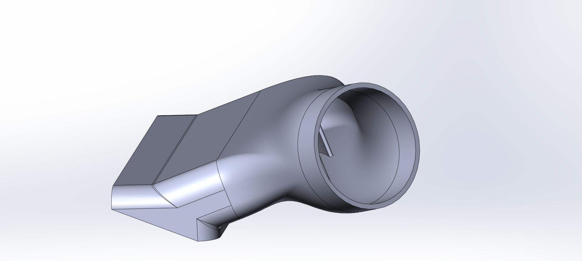
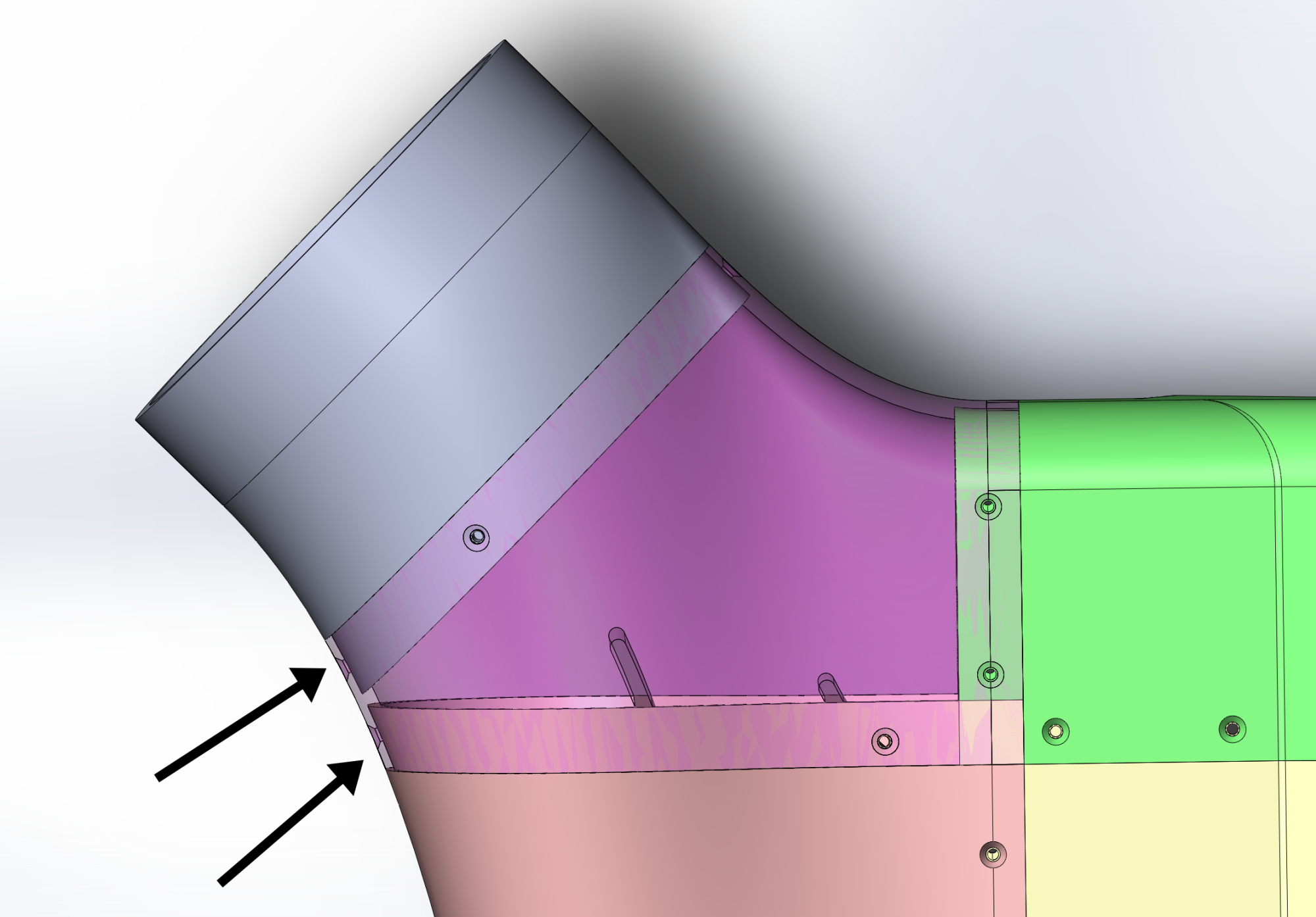
I need the duct output to come out of one side and do so at an angle. This is due to where the AC unit is compared to the rack. For this first pass, I will just eyeball the angle and distance. I can circle back and adjust as needed, plus I can use a flexible hose to take up and minor mismatch.

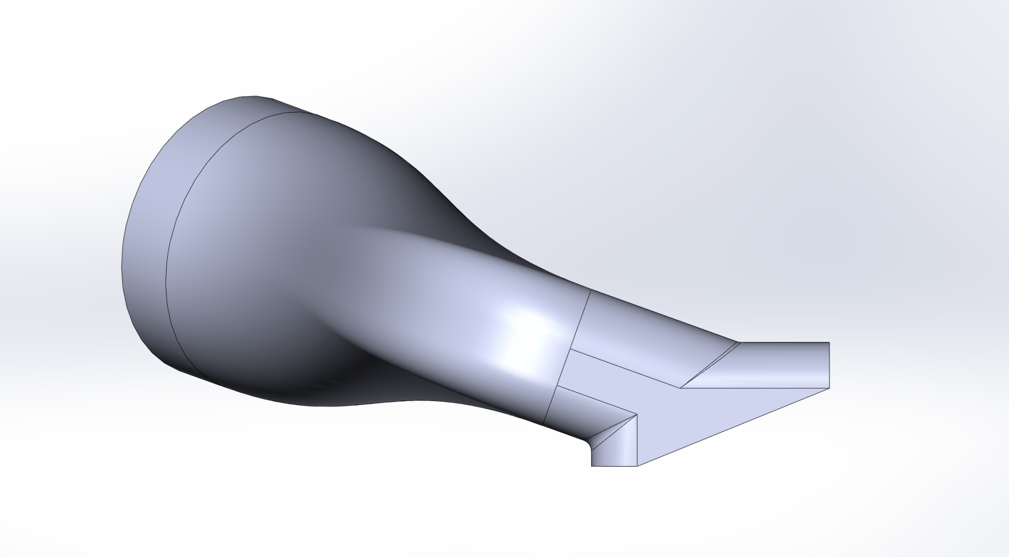
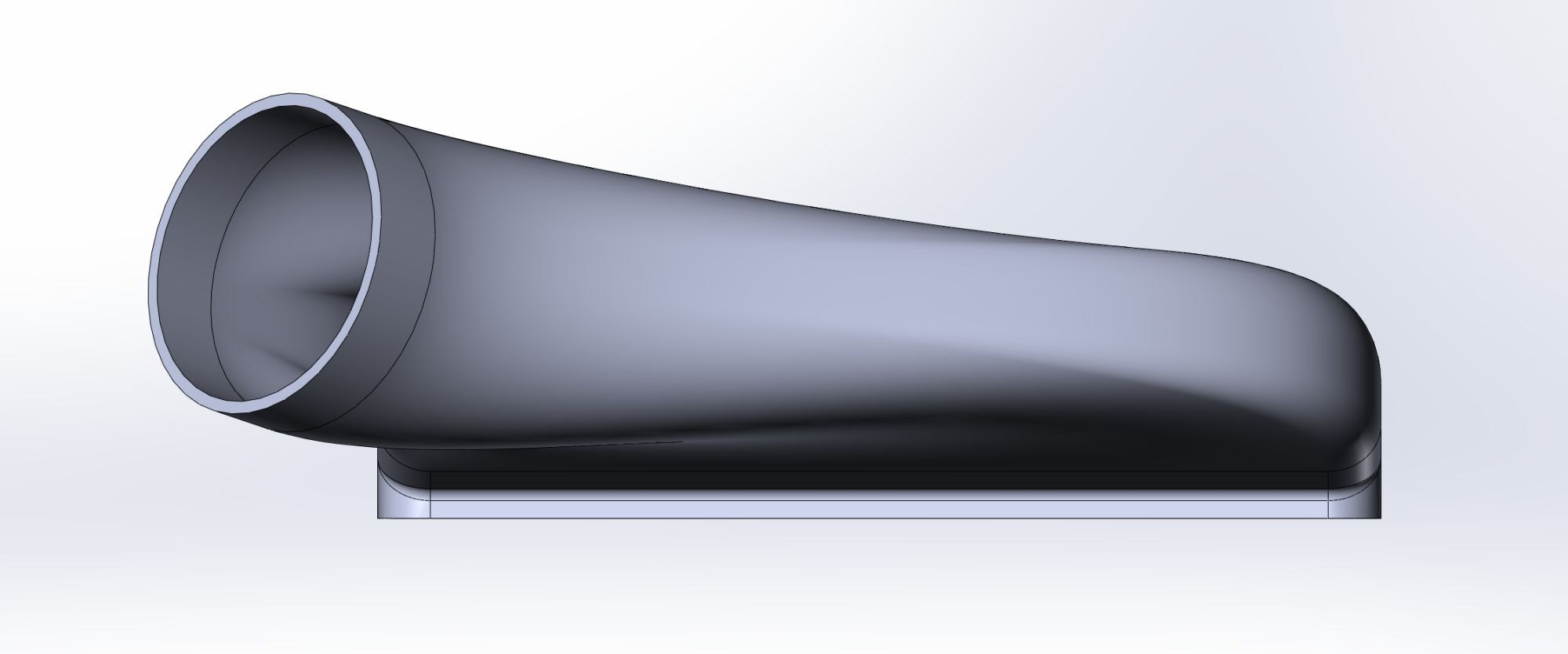
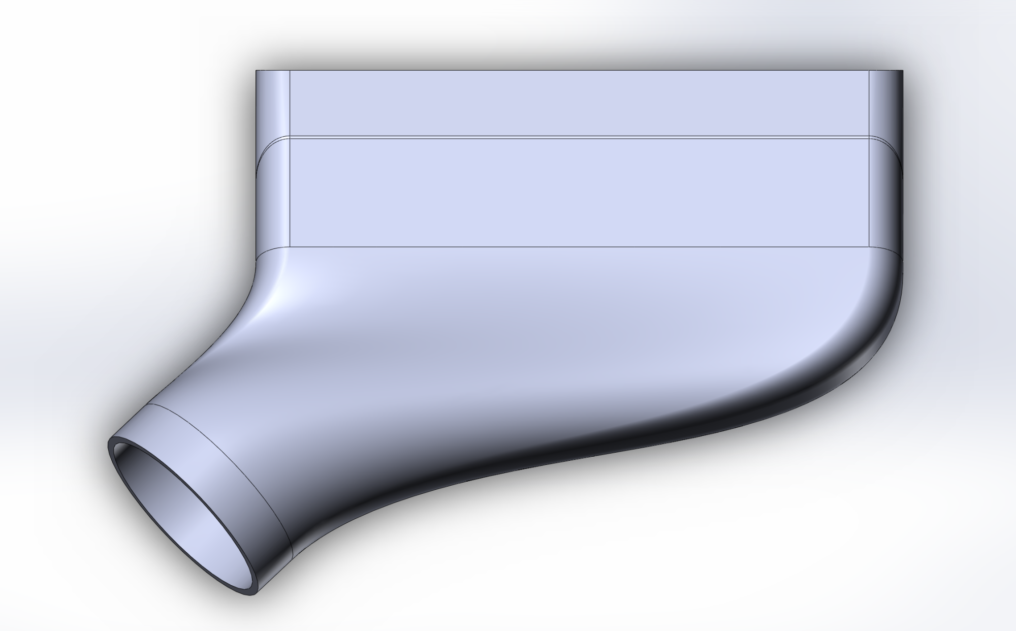
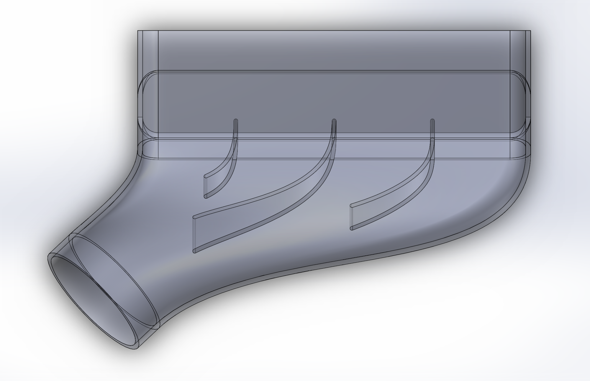
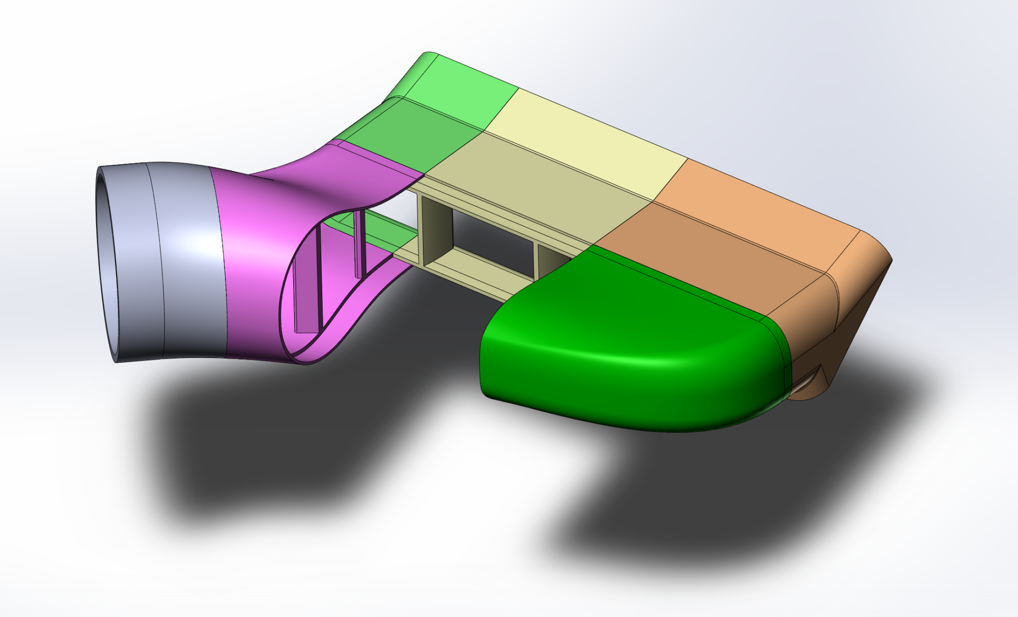
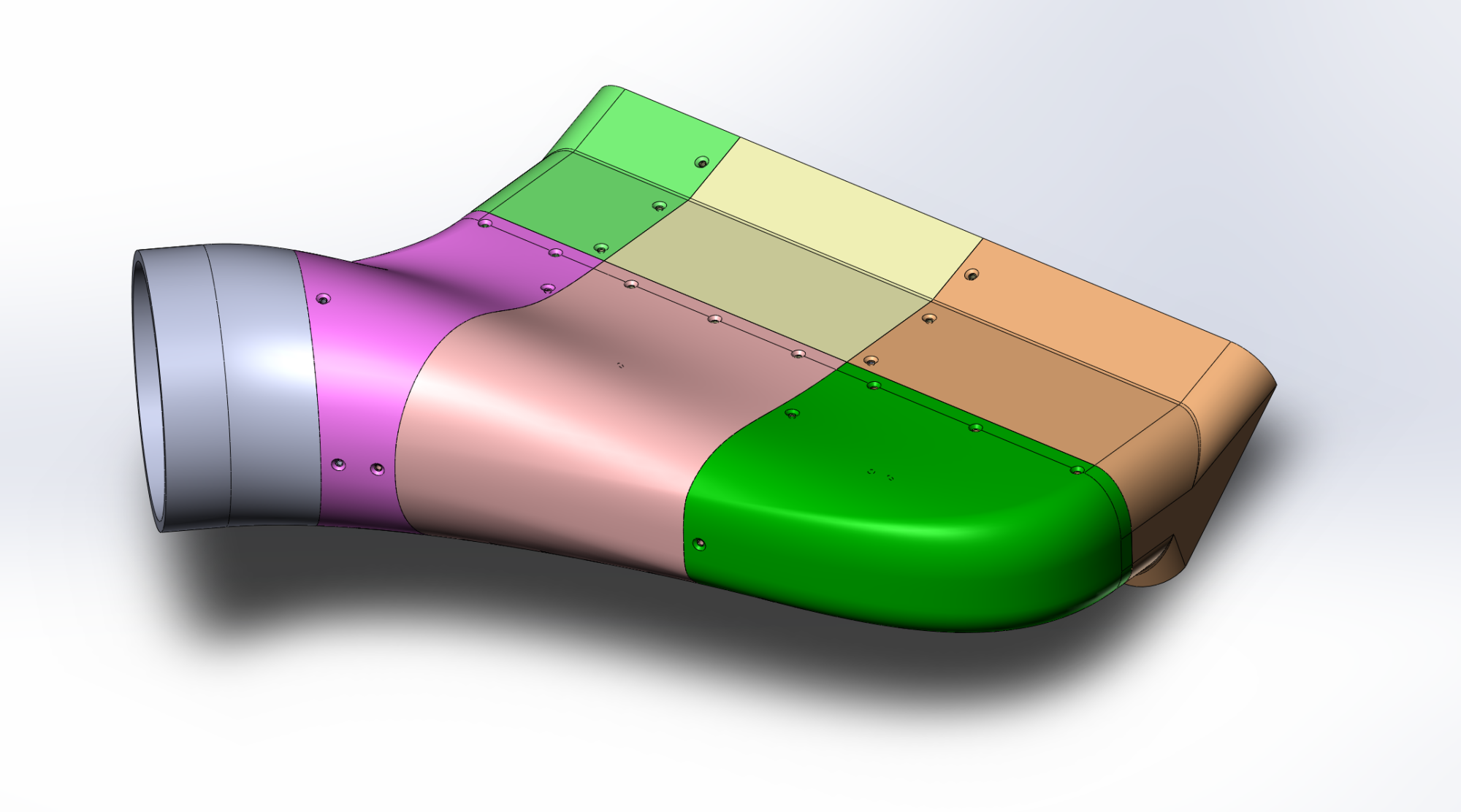
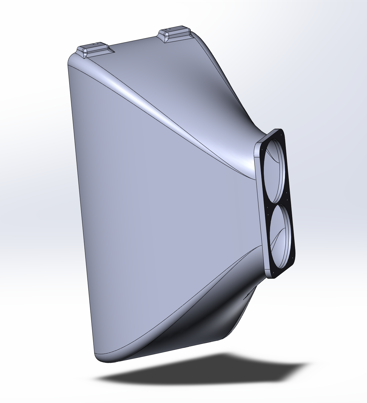
Now, let's go to town on this. I'm thinking the duct should look like this:
1698616024031.png

1698616066805.png

1698616111719.png

1698616172979.png


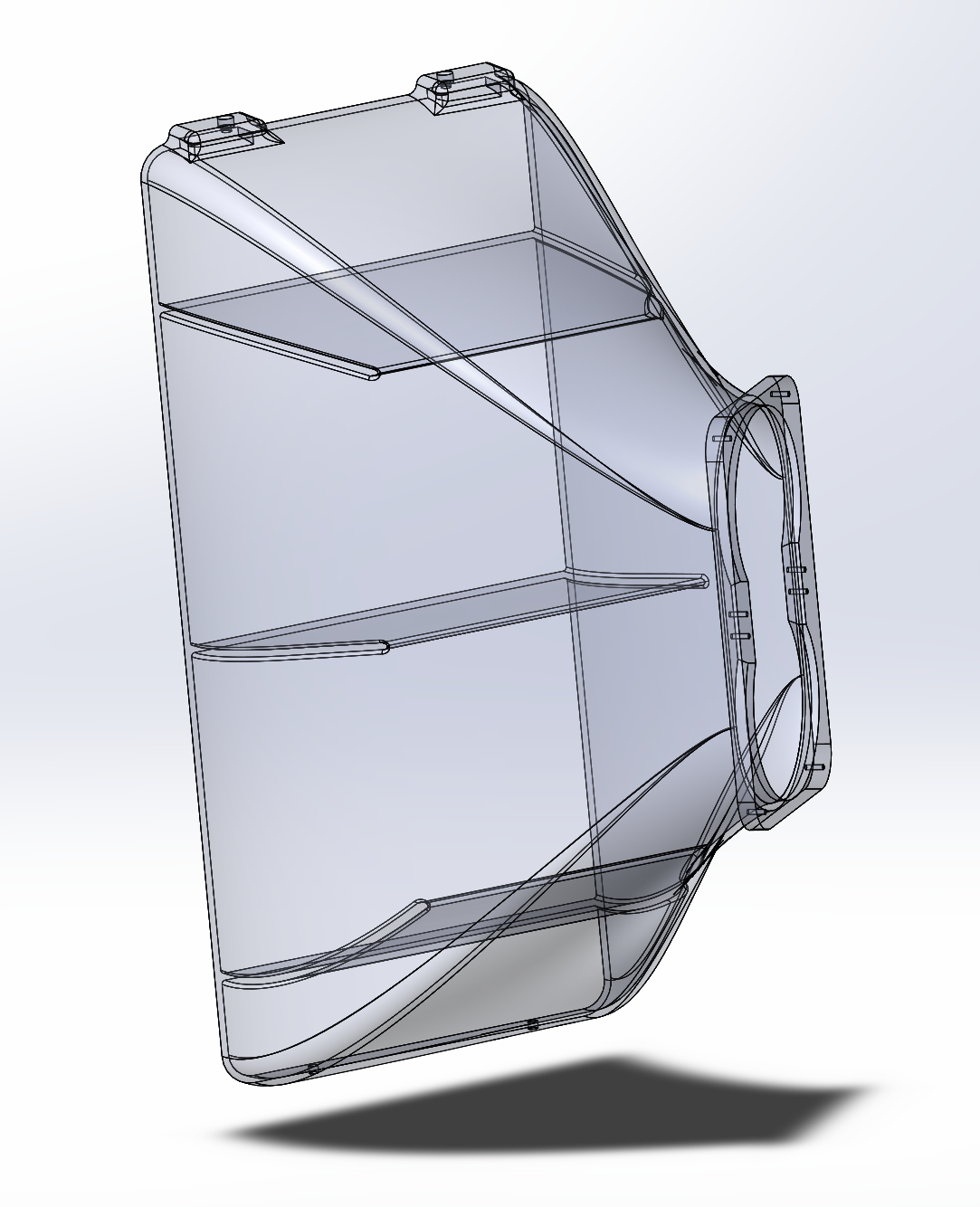
Using my calculated eyeballs, I think I might need some internal flow guides. It feels like the air will hit the near face as a big mass and thus create its own traffic jam as it changes direction. Some internal guides will hopefully help alleviate that:
1698616322207.png


Alright. This doesn't appear to be too terrible. I can work with this. Time to get started fabbing it.

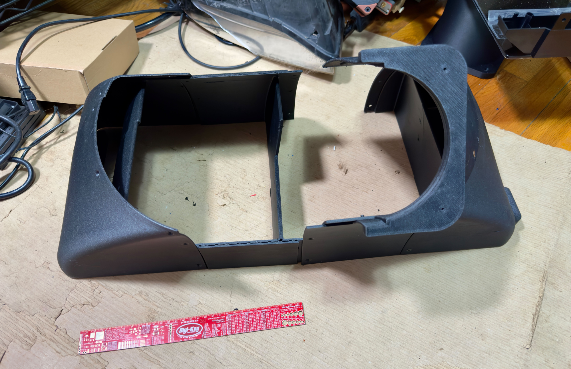
I've been using 3D printers as a professional tool since I was in college over 20 years ago. I've always had unfettered access to them at my jobs, including two jobs where personal use of the Stratasys Dimension 1200, Fortus 250, and Fortus 380MC was not only explicitly permitted but explicitly encouraged. I'm not at one of those jobs now though. The best I can do at the moment is my own Bambu X1C.

The X1C is a great printer. It still has its strengths and limitations though:
  • Nominally, the build area is 250mm cubed.
  • The real world usable build space is much more like 210mm cubed.
  • The printer has a single extruder but it does have a material switching system. I can use this to fudge things and use a second material as the support material.
  • Bambu's PETG-CF isn't cheap, but it is stupidly simple to print. Click print and then parts come out. Absolute brilliance there.
  • Officially, ASA is not a "real" support material for PETG-CF. In my experience, however, it's going to get the job done.
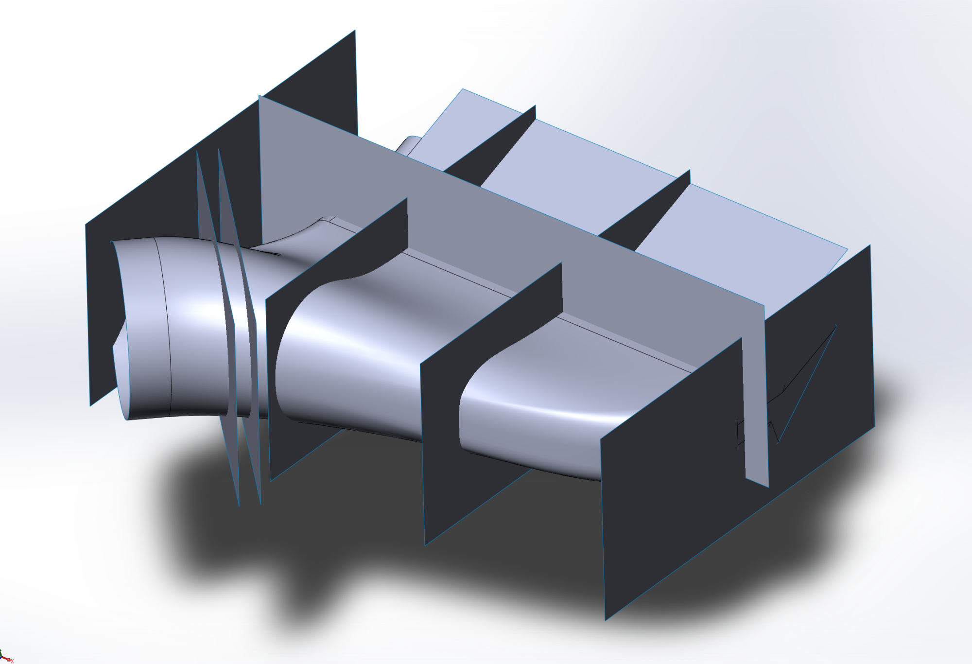
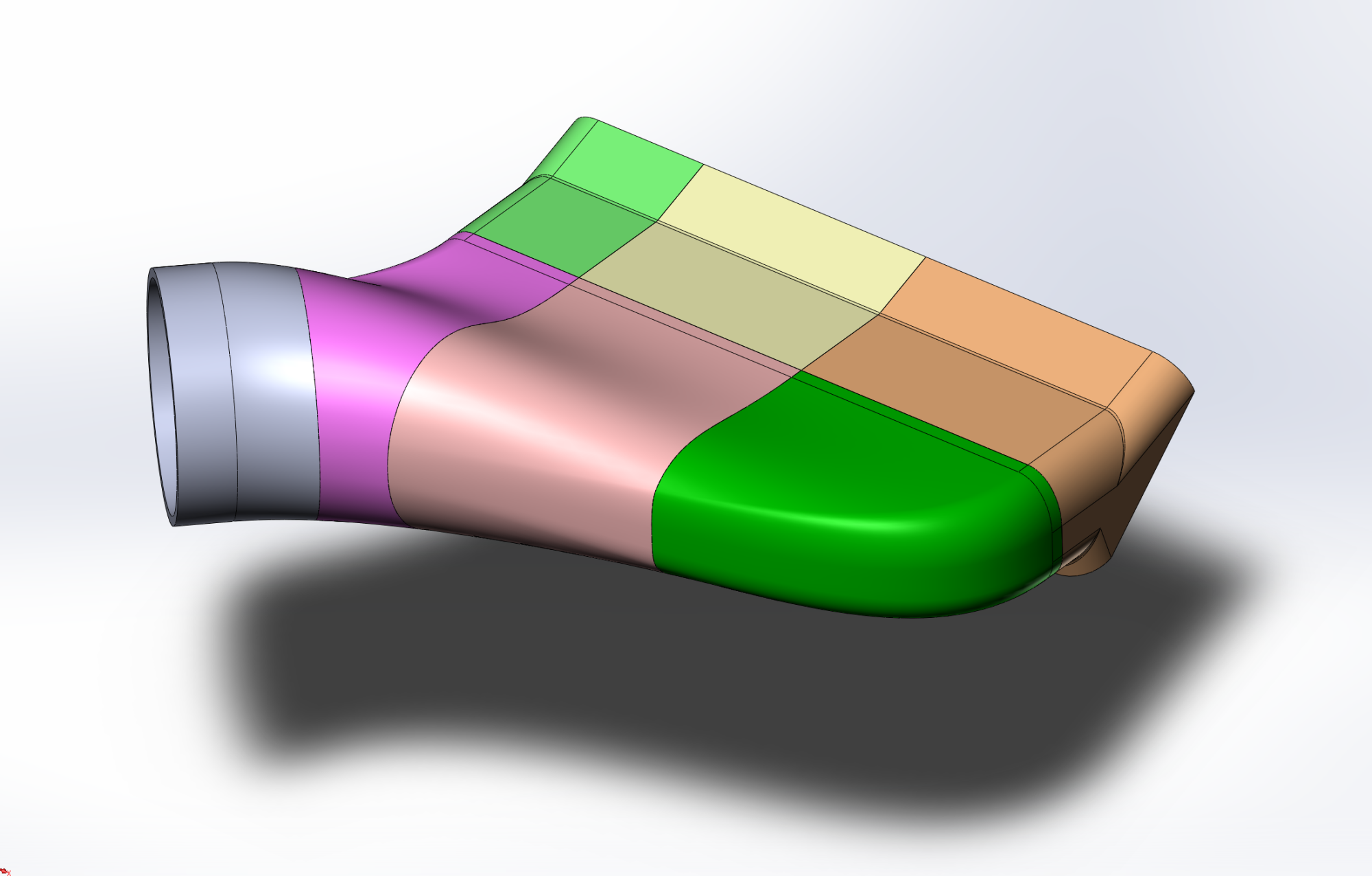
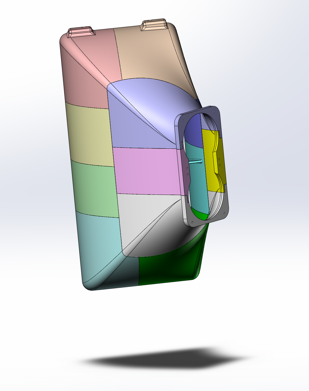
With those bullets in mind, let's start cutting this up for printing. A basic shiplap joint system should get the job done. This can be done with surfacing. I'll make a mid-surface and use that for the "tongue" of the shiplap and keep that aspect a line fit. Simple extruded surfaces will then define the start and end of the joints, and I will combine all of those surface to use as my cutting tools.

1698617141763.png


And now let's do the cutting:
1698617218948.png

1698617255203.png


I'd love to do a sequence of snap fits, but I'm not sufficiently confident in the precision of my measurements to feel comfortable relying on that. I'm going to need something that will allow for a small level of slop and adjustment: screws.

Countersunk screws look nice due to the flush fit. They're also a decent match for this part because the heads are thinner than the equivalent socket head screw. Countersunk fasteners, however, are a dangerous thing. The geometry of a cone nesting in a cone means that they're self-centering. It also means that when you tighten them down, there is a splitting force (like an axe through a log) applied to the component with the countersink. With the anisotropic nature of layered manufacturing (specifically, FDM), this becomes risky. It also means that I'll lose a lot of the adjustability I wanted unless I'm ok with screws not being completely flush with their countersink. Given that this is just Rev 00, I'm ok accepting this. I can always fix it and reprint Rev 01 later. Plus, I like to live dangerously.
1698617618100.png

Looking nice. Now, it's time to print.

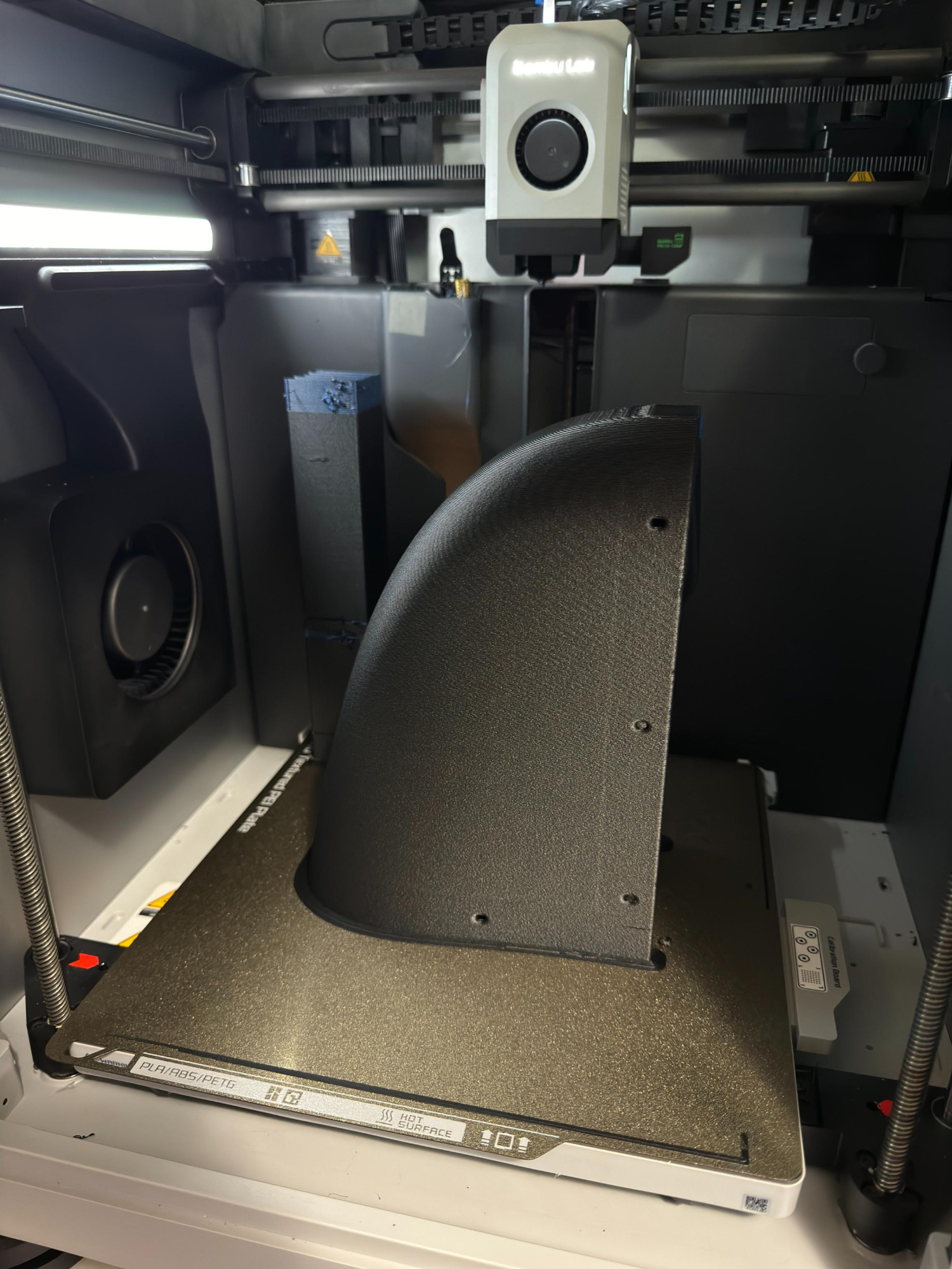
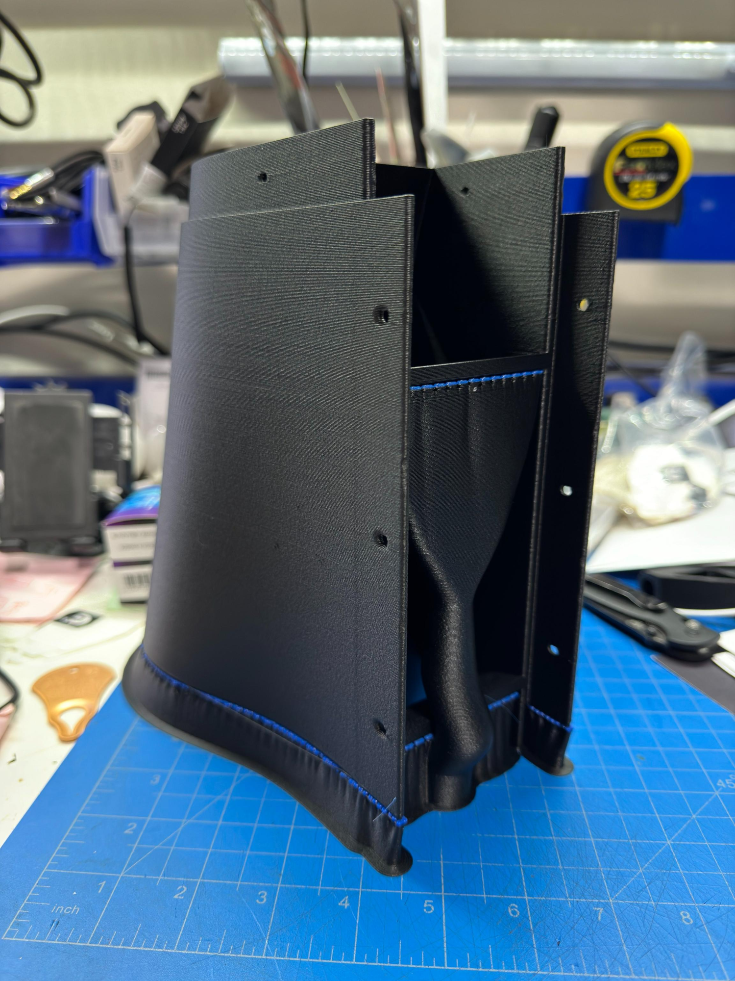
For settings, I'm going with the 0.8mm hardened steel nozzle, PETG-CF model material, ASA support material, and 0.4mm layer height. Pretty much the default printing profiles but with a handful of tiny adjustments like not purging into the model or support. Support structures are what Bambu calls Strong Tree and I found that 2-walls on them was the most reliable due to their height.
1698617995009.png

1698618044400.png


During fitting I realized a stupid error I made: there is a significant undercut on a couple of the shiplap joints. Fortunately, for now, the lower one can be fixed by splitting one end of the vanes from the wall and the second can be resolved with a few seconds of time and a Dremel with a grinding tool.
1698618500478.png

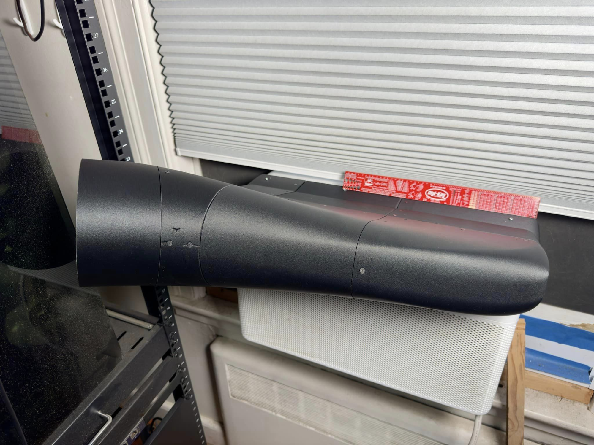
And with that, Ta-Da! We have ourselves a duct!
1698618569341.png


Based on how quickly that dust got deposited on the 1000D, I'm thinking I will add an inline filter somewhere. Would a tiny HEPA filter be too restrictive? I guess I'll find out later.

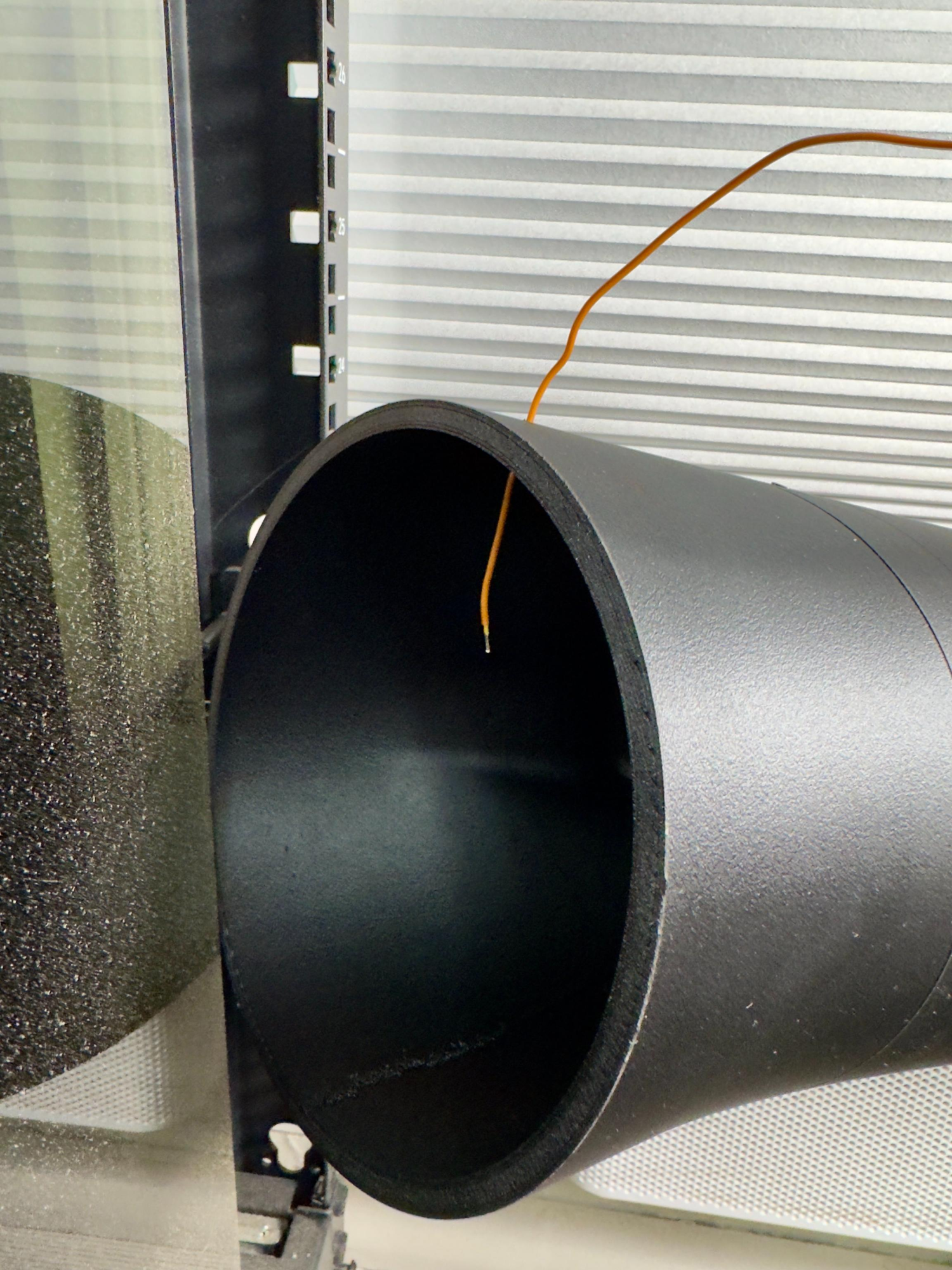
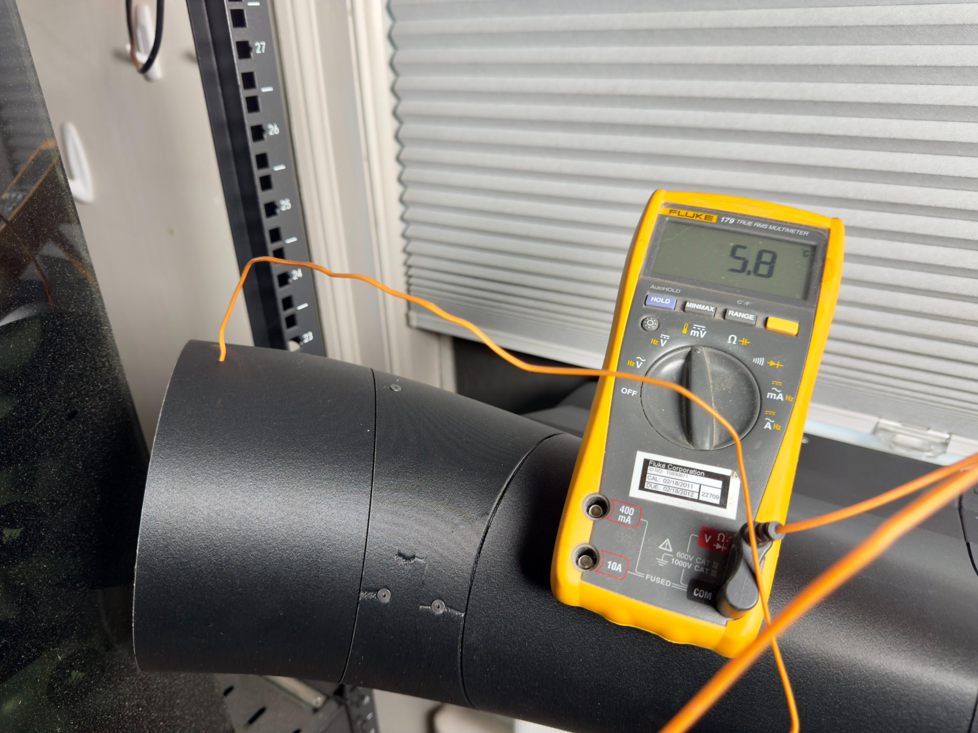
You know, now that it's set up, it might not hurt to use this opportunity for a basic sanity check. I've been banking on 20C air as my safe target, but just how cold is the air coming out of the AC in real life? Let's stick a probe on it and find out.
(nerd check: the sticker shows an expired calibration, but I have non-traceably calibrated this unit against a traceably calibrated on within the last 12mos)
1698618851822.png

1698618881482.png


Alright. I think the 6 radiator target should be enough. Heh.

Time to move on to the duct for the 1000D.

Clicksaver: I remembered partway through this that the design was going to be wrong given one major update that I did after the CAD was already haflway done. Because I bought a new front panel with the intention of removing the glass and then mounting the duct directly to the plastic front panel mounts, the duct was going to be way too tall. The gap between the mounts is significantly taller than the actual 480mm front rads, so there will be a ton of wasted air. Since that will still work great (just not optimally from a system-level POV) and this is intended to be a temporary setup, I figure I'll just roll with it anyway rather than spending the time making it right.

On to the CAD:
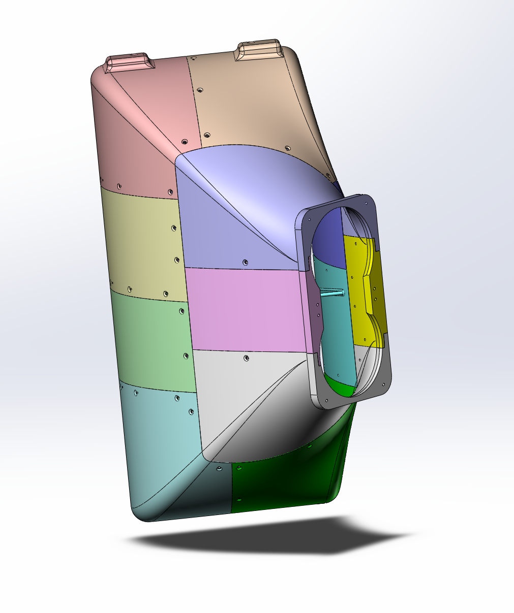
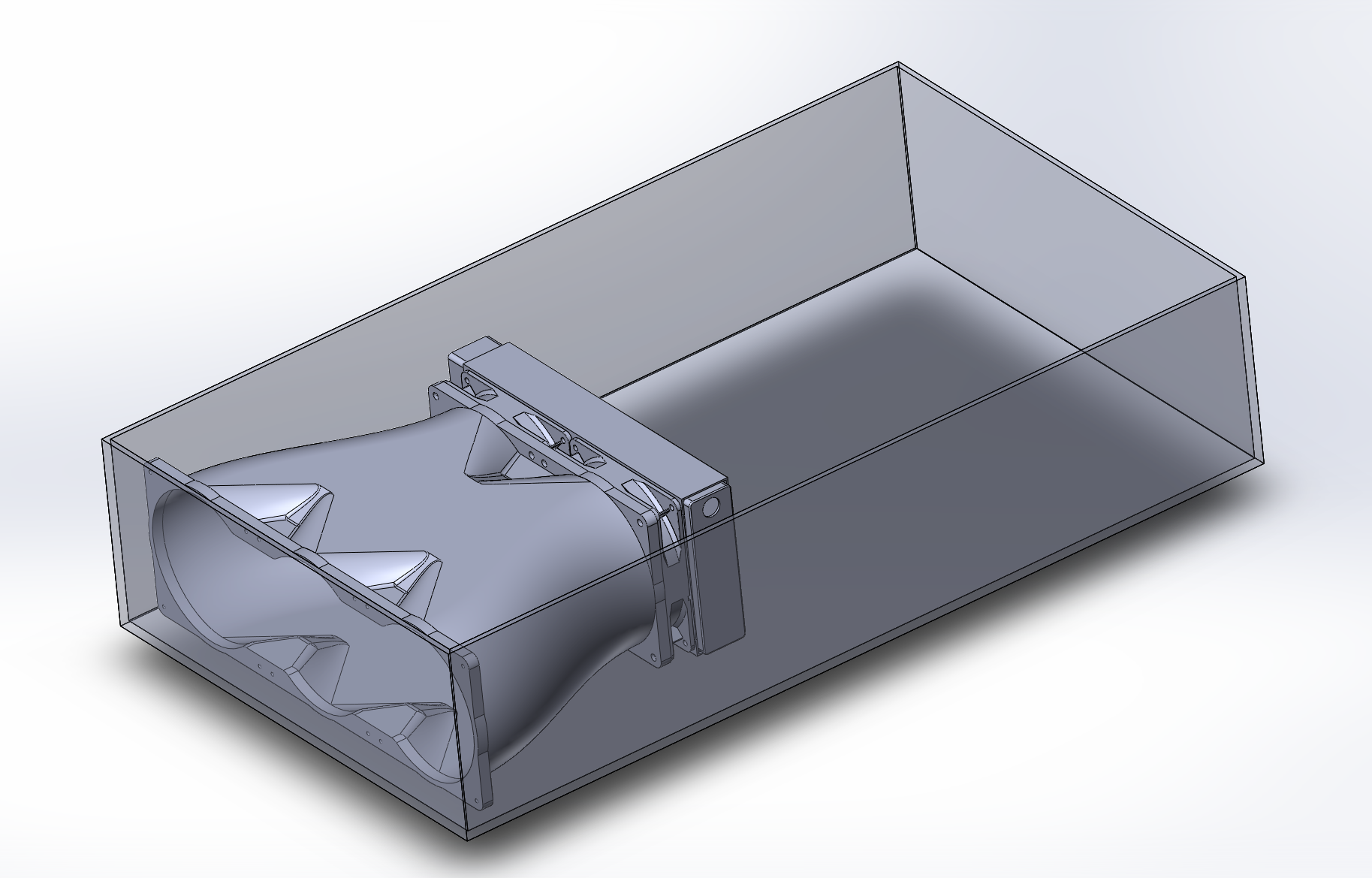
The basic approach here is the same as the AC duct wherein I set planes in approximately the locations & orientations of the inlet and the outlet, I draw the profile for the inner dimensions of the inlet and outlet shapes, connect the two profiles with a loft, and then I shell outwardly to create the duct. That, plus putting in a flange for mounting a pair of 140mm fans and two bumps for mounting to a bracket (which then mounts to the front panel mounts) leaves me with this:
1698893525401.png


And then some internal air guides/vanes are added:
1698893656856.png


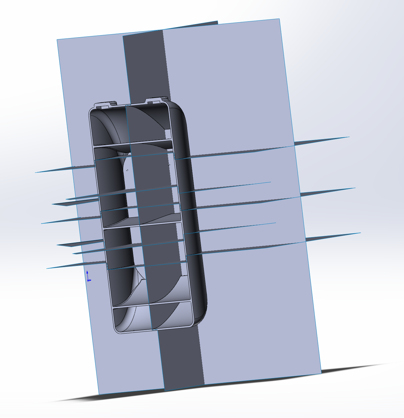
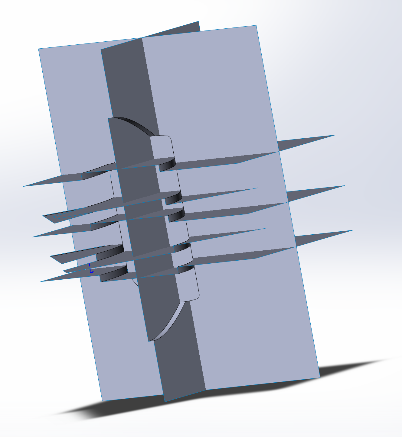
And now the tricky part: cutting this up into chunks that will fit in my Bambu X1C. I'm using the same technique as with the AC duct with a midsurface that gets combined with a pile of cutting planes/surfaces. After some futzing around with trying to get the parts to both fit in the printer AND all get printed in the same orientation (good aesthetics are scientifically proven to reduce core temps), I gave up on the orientation part. Let's cut.
1698894057869.png

1698894107219.png

1698894299503.png


And then after that, we can add the screws for sticking everything together.
1698894375792.png


Probably not the worst design I've ever done, but it might be close.

Oh well, it's time to slice and print.
1698894758276.png


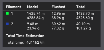
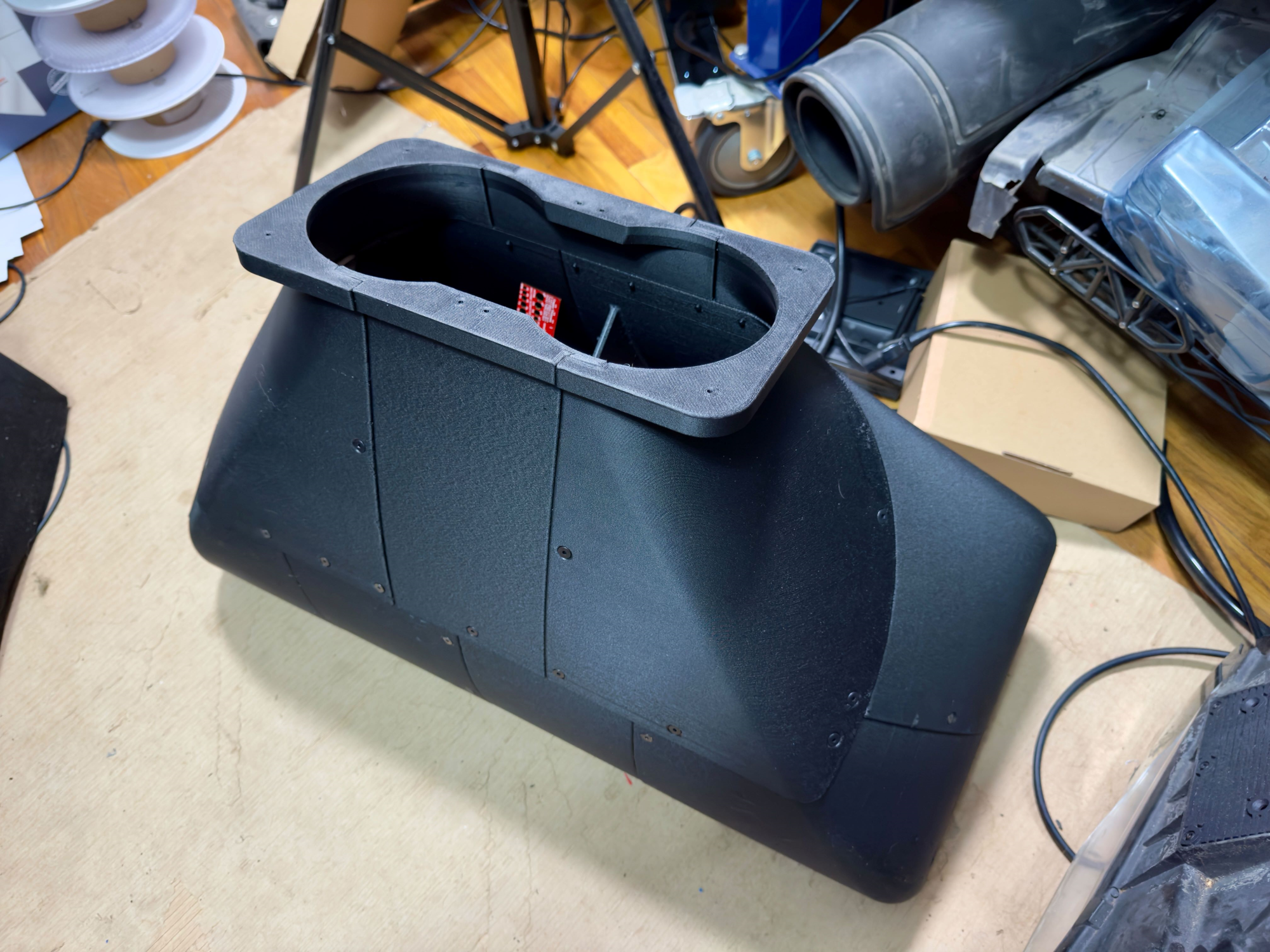
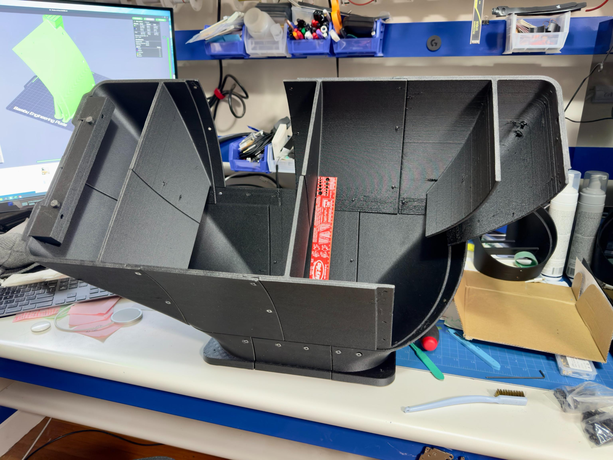
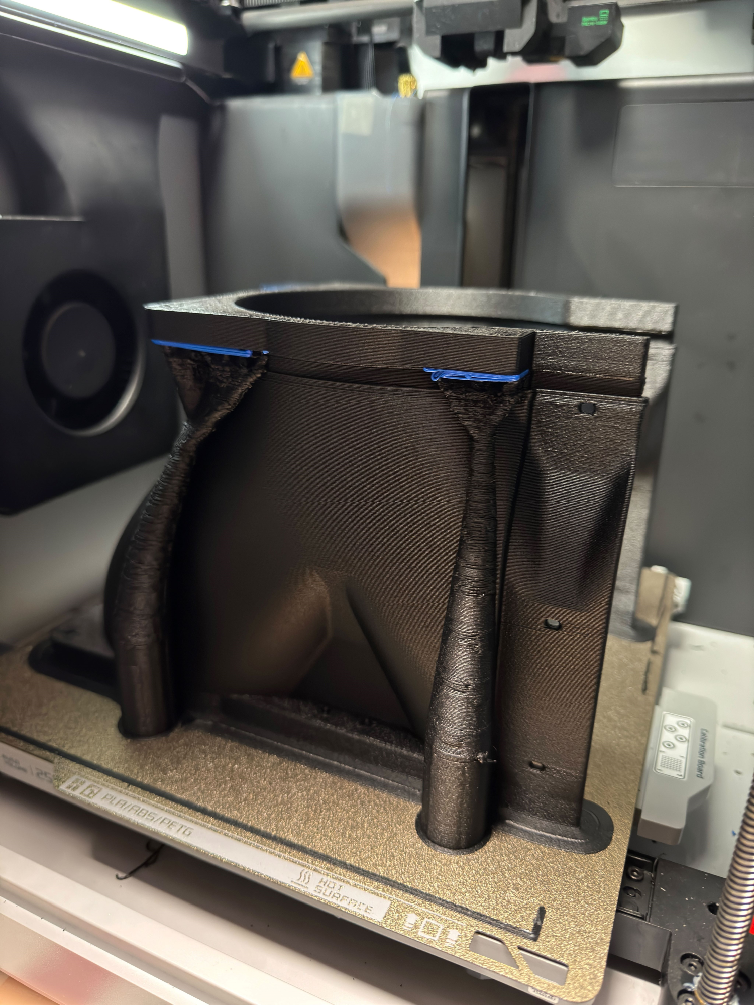
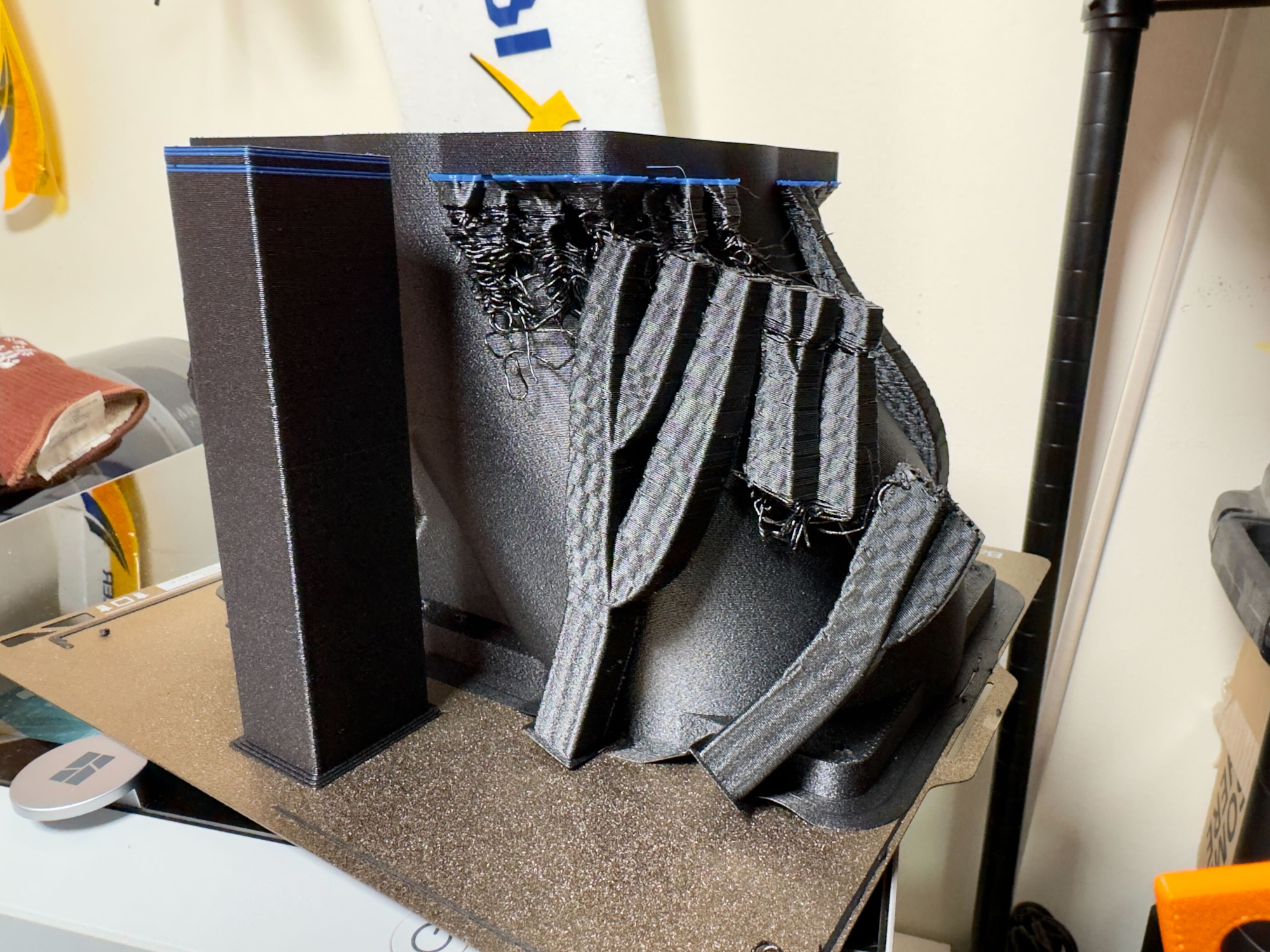
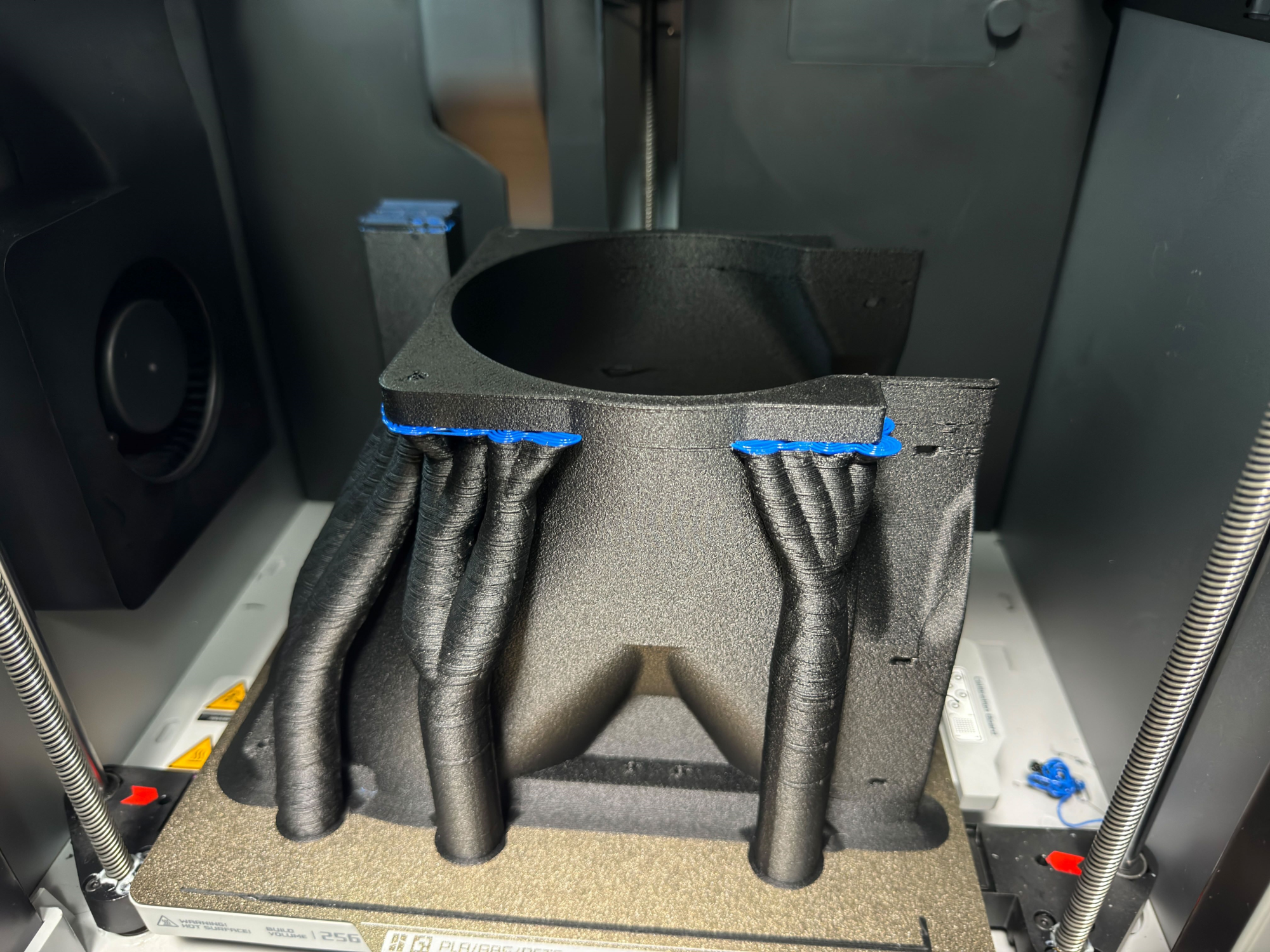
It ended up taking about 12 days of printing to get this done. There were 12 panels total and the first 9 printed absolutely perfectly on their first try. Then, completely out of nowhere, everything went south. As of 11/26/23, I'm still trying to figure this out. There have been over 450 hours of bad prints so far.

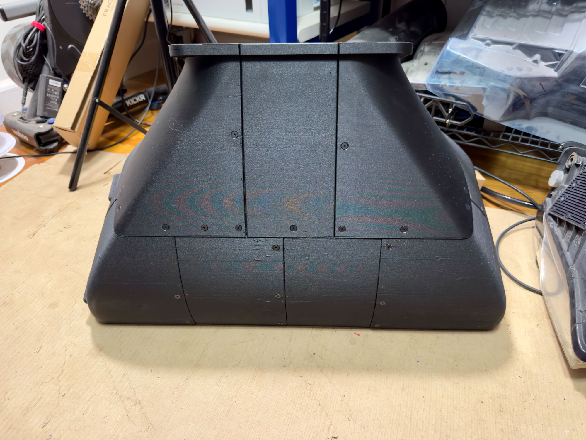
Anyone, once it was printed, I tapped the holes and cleaned up the countersinks. And then I assembled it, and....

LMFAO. This thing is sofa king big. The pics really don't do it justice. If you look closely, you can see the ruler for scale in the pics.
1701061826135.png

1701061867745.png

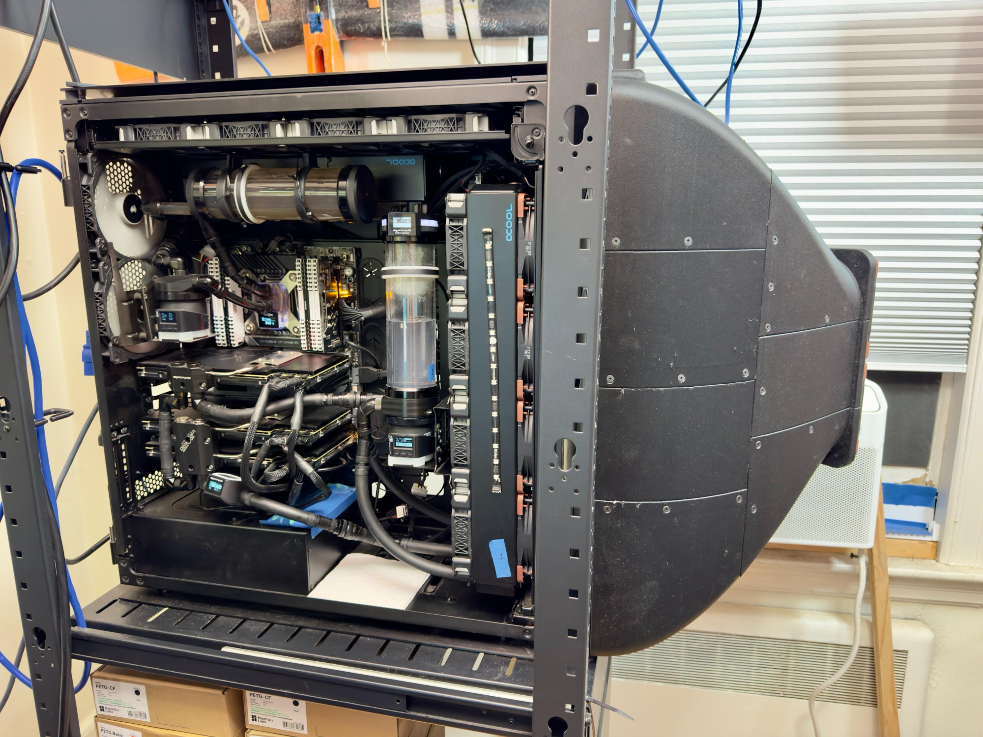
Mounting this up requires taking off the front panel glass. Taking off the front panel means taking both radiator modules out of the case. With all of that stuff coming out, it was a good time to do some other updates. I replaced the Corsair ML120 fans with Noctua NF-F12 3000rpm units. Additionally, I replumbed the GPU loop so that the radiators are in parallel and the pump is mounted to the front radiator module. The replumbing meant I could knock 3 QDC pairs out of the loop. More on that in a sec.

So I did that stuff, and then I mounted the duct.
1703827827442.png


Lol. Yup, it's still hilariously big.

The next steps are:
  1. Replace the janky pump mount with a good one as soon as it gets delivered
  2. Replace the remaining 4 ML120s with Noctuas as soon as those get delivered
  3. Take some performance data
  4. Attach the duct to the AC unit and take some more performance data
  5. Step back and lol some more


Changes pending for Rev 01:
  • Replace #4 fasteners with #8
  • Add counterbores for mounting screws
  • Fix the undercuts in the part split around the output pieces (grey and pink). Total rookie move. Oops.
  • Align all parts in the same print direction for purely aesthetic reasons
 
Last edited:
Updated Phase 1 with some CAD shots of the 1000D side of the duct. Also stuck most of the Phase 1 pics behind spoilers to reduce scrolling.
 
Ran into some printer trouble. It isn't really resolved, but I think I have a workaround that should at least get me some rough parts to finish off Phase 1. Here's a progress pic with a few of the bad/broken parts. The size of this thing really registers in person.

1699493287166.png


Also got started on Phase 2. Not really much progress yet since I'm still bouncing some ideas around. I wanted to make this 4U, but if I have 3x140mm fans on the front panel, there isn't enough space left for the fluid connectors. If I just have 2x140 feeding straight through, I end up with enough space to make it work in the original 4U. That probably won't have any negative effect on the cooling capacity.

If I make it 5U, then I would have space for a whole bank of fluid connectors and could connect multiple systems to it in parallel. On the other hand, I was intending to put the pumps and controller into a different 2-3U box and that would also be a good place to have such a connector bank. Decisions, decisions.

1699493784726.png
 
Getting closer. Just two parts left and then it can be mounted on the 1000D. I can't help but LOL at the size of this thing.

1699651823442.png
 
Good news: The 1000D shroud is fully printed and assembled!
Mixed news: The Corsair machine has suddenly gotten really busy, so unfortunately, I haven't taken it offline in order to do the front panel swap yet. I will hopefully get to do that soon
Bad news: The printer (Bambu X1C) is an unknown problem with it and has only been able to produce a single good print for the last 450 hours of trying. This is also why a few of the duct parts look far worse than the rest.
1701050359782.png

1701050522060.png


Good news: It was able to print one half of the front duct on the rack cooler
1701050590688.png


Mixed news: After measuring things, it looks like I'd need 5U in order to fit the 280mm rads as well as the front panel connectors. That means 10U to double stack, plus more flow restriction from having more QDCs. On the other hand, a single unit with double stacked rads inside needs just 8U. So, I think I'm going to pivot to making this an 8U unit with 6-8x 280x45mm rads inside. TBD whether I do with with 2 parallel airflow paths or one large 280x280mm one. Since I'm 3D printing ducts anyway, maybe it would be fun to test it out with all three possible configs of quad, dual, and single routing. I just need to decide which one to do first.
Mixed news: This is going to require a sheet metal chassis to support. The good news is that I may try making my own using 3D printed tooling if I can get access to a suitable hydraulic press if not an actual press brake. This will be a pretty big case to make 3 sides from the same sheet, so I will likely be making it from individual panels. That will still require a fairly large press though.
Good news: With some thoughtful routing, there may even be enough space in 8U to include a dual D5 and an aquaero, thus making this a fully self-contained unit.

Updates to follow.
 
Printer is still having trouble, but I have a heavy-handed workaround which has it printing again. The workaround, however, adds about 50% to the already long print times.

Anyway, I decided that the easiest way to make the first version of this cooler happen is to just stack two of the original radiator and duct sets on top of each other. I can always change it to one large flow path later. I also decided that I'm going to try and fit the pumps + aquaero in here. To do that, the rads will have to be offset to the side. I've updated the CAD for the front ducts to handle that offset while still being a 420 into 280 setup.

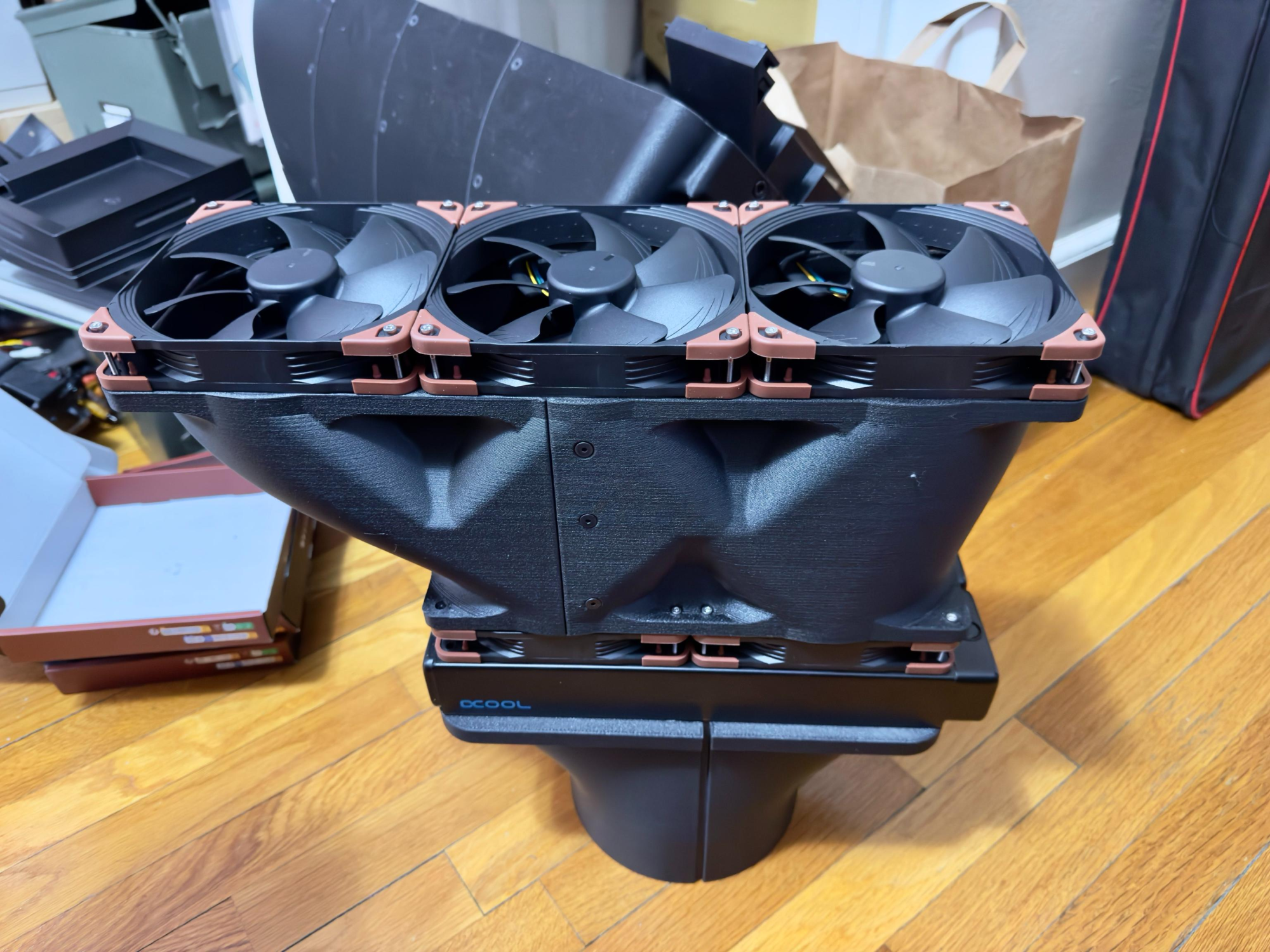
Got the first front duct test print done. While putting it together, I realized that I forgot a tool clearance on the section with the big offset. The screws are missing there because I can't get them into place. I've updated the CAD to fix that and will be printing a new piece this weekend. In the meantime, here it is. That's a 280x45mm radiator btw:
1702008738268.png


The bottom section is just a stand. A 280 to 280 duct to connect the next rad goes there and will print this week.

After the first full test fit, I'll update the big offset section to have a relatively small bypass for a duct that will run down the inside of the box for cooling the electronics.
 
Strange in a good way. But why? :)
Sometimes I get too bored for my own good and then stuff like this happens. :LOL:

Updated the post to add a pic of the duct mounted up. Just waiting on a few parts to arrive and then I'll finish the update and start generating data.
 
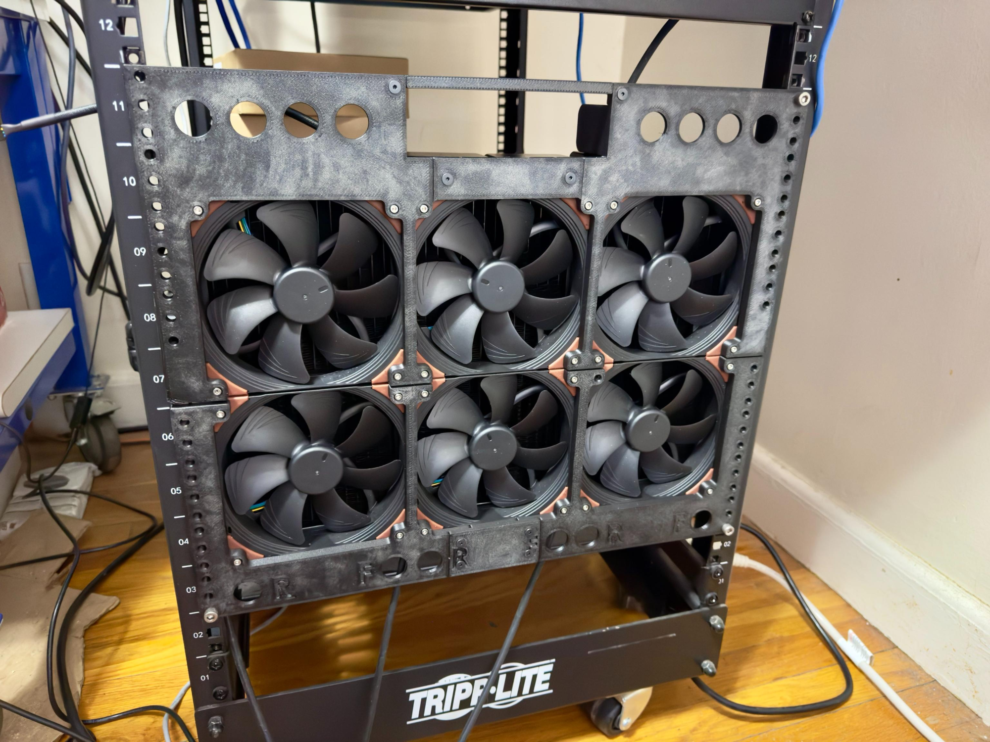
Slowly making progress in between distractions. Did a quick test fit last night. Based on what I learned, I will be adding a couple of ribs, a couple of alignment features for the top and bottom halves of the face plate, and possibly making new ducts that are mechanically linked to each other even if the flow remains separated. Still a bunch more to do in addition to that of course.

Top holes are for the inputs & outputs, bottom holes are for draining + vacuum filling from the bottom up. Rectangular opening is for the Aquaero display.

1707755304028.png
 
Fun project! I'm following along.

I've been toying with the idea of using my 3D printer to make some custom ducting and parts to fit as much cooling as I can in an ITX case 😂 Once Zen 5 launches I'll likely do a CPU upgrade and move from the NCASE to something else. Goal is to either fit my existing loop in a smaller case, or go up in size slightly (M1EVO is ~2.5L larger) and add more cooling.

I like the CF PETG filaments too, although I don't have the ability to print supports in a different material. I've been using Atomic PETG-CF, though like you said the stuff is not cheap.
 
If you're comfortable with the CAD, 3D printing is an awesome solution for ducting in builds. A drawback to such well controlled flow though is the increased risk of critical yet not major components accidentally getting cut out of the flow path. For example, with an external cooler handling the GPU and CPU, it is still important to have case fans for everything else on the motherboard.

As a side note, one thing I'm hoping to get from this is insight into whether I should go with 560s on the next one versus running two of these 280 setups in parallel. To that end, I will be taking temperature data from the input and output of each rad. Since I'm planning to plumb this as 3 parallel pairs of 280 rads, the coolant is going to be moving pretty slowly. It's possible that changing the rads to 560s won't add much extra cooling as coolant temp may have already bottomed out before reaching the end of the first rad.

Anyway, it should be interesting to see what the data shows once this is done.
 
  • Like
Reactions: Epos7
like this
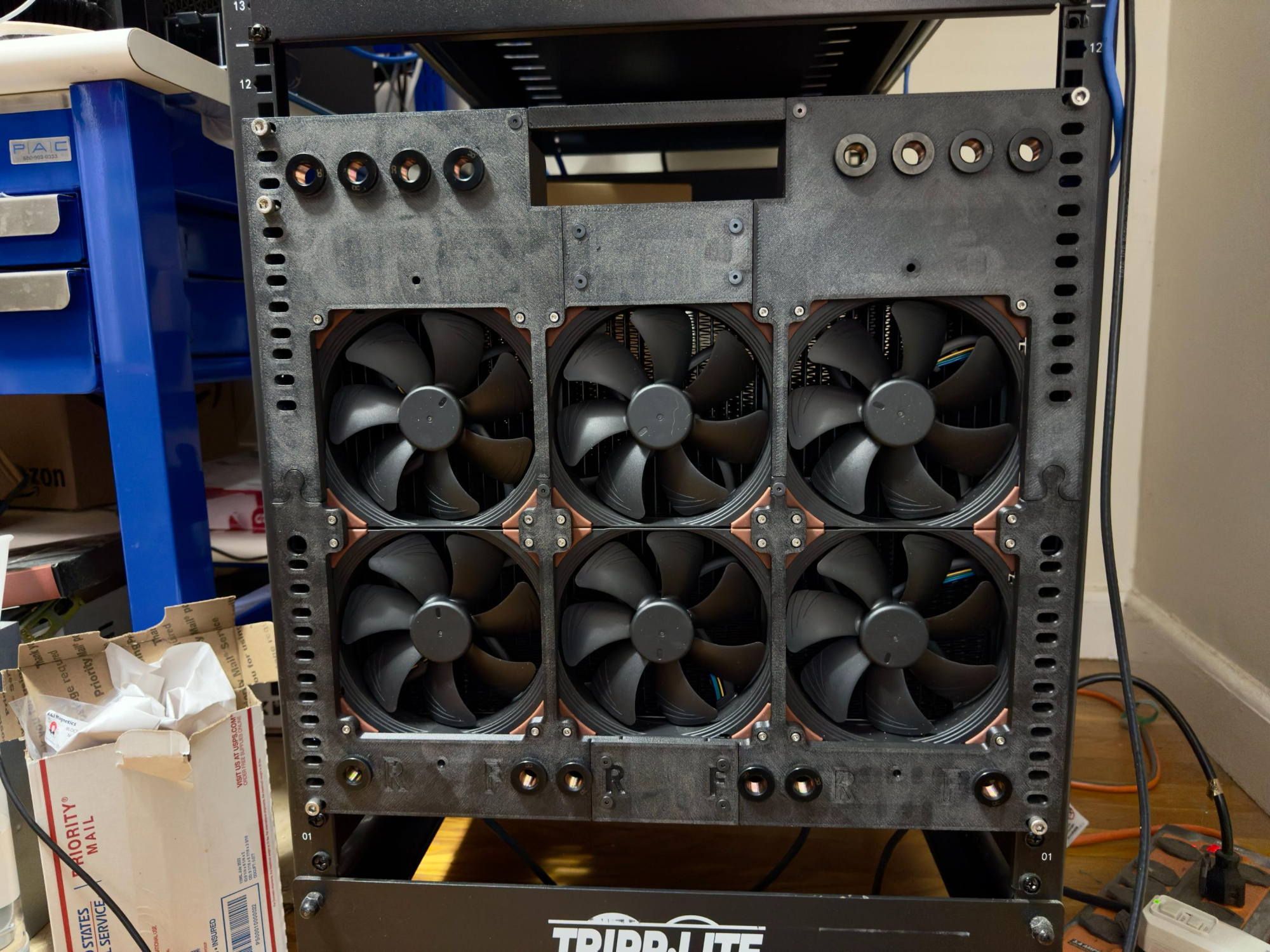
Made a few quick updates:
  • Added 1U of height. It didn't technically need this, but the extra space will make filling in the rest of the details much easier. And since it was already 9U, what's the harm in growing to 10?
  • Added beefy ribs at the top and bottom. The first gen that I posted above was pretty floppy once even just the front rads were mounted. Now it is solid.
  • Added alignment features for the top and bottom sections. Now all of the mounting holes actually line up with the rack.
  • Changed the rack holes to slots
  • Added a little bit more clearance behind the bulkhead connectors to make tightening the backing nut a bit easier
  • Added mounting holes for future AC duct
Stuff left to do (not a comprehensive list):
  • Test fit Aquaero (waiting on delivery)
  • Design (or buy) handles. Getting this thing onto the rack is a PITA.
  • Buy shoulder screws to aid in the mounting process.
  • Adjust drain port locations. Fronts are currently too close to the actual drains on the rads for fittings to clear each other.
  • Figure out the manifolds. I have both EK and Alphacool manifolds and neither is particularly well suited to this. Will also need to mount the eventual solution somewhere.
  • Add a second color of PETG to the AMS so the front panel labels can be colored and flush. Picking the support out of the debossed labels is a PITA.
  • Mount the second set of rads plus the D5s to the latest test print to confirm that this is actually strong enough for all of that.
  • Change out the alignment features for ones that also screw together. Adding strength to that joint between the top and bottom sections would make me a lot happier.
  • Figure out the QDCs. May have to give my CPC rep a call and see what he suggests. Not a fan of Alphacool's since they always have corrosion issues and are major flow restrictors.
  • Add mounting holes for fan guards.
I'm hoping this will be the last update post until it is ready to be connected to a machine and tested, but I might end up posting one more.

(Side note: the threads on these rads are garbage. Alphacool, you should be ashamed of yourselves.)
(Side note 2: Upgrading to 420 rads would grow the height by 4U and bring the total to 14U. Good to keep this in mind for the future)

1708232932939.png
 
Last edited:
(Side note 2: Upgrading to 420 rads would grow the height by 4U and bring the total to 14U. Good to keep this in mind for the future)
fwiw, 420 mm is less than half the length of most racks, front to back. Maybe not ideal in your case, but worth a mention anyway.

Really cool build, keep us posted! :cool:
 
fwiw, 420 mm is less than half the length of most racks, front to back. Maybe not ideal in your case, but worth a mention anyway.

Really cool build, keep us posted! :cool:
The first layouts I mocked up in CAD were actually different front-to-back layouts, both flat and different angles. It was less space efficient than I was expecting, largely because the airflow gets choked at extreme angles (like horizontal) unless I add extra space to accommodate for that.

I know Koolance uses that layout for their coolers, but they require a certain amount of clear space above and below them, plus they're running louder fans.

One thing I'm curious to test with this setup is how many radiators in a row actually make a difference when you're running these 3000rpm Noctuas or even some beefy Deltas. That's getting ahead of myself though. I still need to finish the first iteration.

Current mental roadblock is what to use to power this since that will have to be mounted somewhere. Sorta tempted to just have a board made with a nice connector breakout and regulator design. Then I can feed it from an ordinary DC power brick zip tied to the rack.
 
  • Like
Reactions: Nobu
like this
Back
Top