X299 VRM Coolers Are Being Described as a "Disaster"

Megalith

24-bit/48kHz
Staff member
Joined
Aug 20, 2006
Messages
13,000
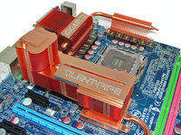
Overclocker der8auer is contending that X299 boards have bad VRM coolers: temperatures reached as high as 100°C on the board he tested. He estimates that the VRM modules are probably at Tjunction max, and the single 8-pin connectors on PSUs can hit 60°C when overclocking the 10-core models. “If I take off the heatsink and just put a fan over it, there's no problem whatsoever.”
 
It's very generous to call those things heatsinks. It's a decorative cover, at most. If anything, it's acting as an insulator.

The power cable heat, I would argue, is due to the power supply he was using with the type of connectors and extra lighting it has. Doesn't detract from the fact that these should come with an extra 4-pin EPS on the board, at minimum.
 
It's very generous to call those things heatsinks. It's a decorative cover, at most. If anything, it's acting as an insulator.

I wonder if it would have been so bad if there was air blowing on these. Although motherboard manufacturers should have assumed if someone gets one of these boards that they will be using water cooling for the CPU while overclocking..
 
I wonder if it would have been so bad if there was air blowing on these. Although motherboard manufacturers should have assumed if someone gets one of these boards that they will be using water cooling for the CPU while overclocking..
Maybe, but there is still the heat soak issue in the motherboard PCB. Might as well rip the damned thing off if you're going to point a fan across them.
 
Is it me, or is the heatsink on those VRM's have any exposed fins? It's almost as if they expect the aluminum to soak up all the heat than dissipate it on the extremely small surface area in a place that barely gets airflow at all as it is.
 
Is it me, or is the heatsink on those VRM's have any exposed fins? It's almost as if they expect the aluminum to soak up all the heat than dissipate it on the extremely small surface area in a place that barely gets airflow at all as it is.

It may be a little of form over function.

Yeah, what do you expect? And this is also ASUS and the first released X299 ASUS boards at that. Cutting corners and either not testing or the people who have the final say decided to not allow adequate cooling even though the engineers told them it wouldn't work.

The first gen boards of any platform tend to have stupid issues such as this.

Go back and look at x58 and x79.. and even x99 if I remember correctly although I haven't even messed with an x99 setup.

Never buy gen 1 on day 1. Any of these issues they'll probably have worked out in a couple months.
 
But those RGB LEDs are working great, though! Priorities.
Dammit, you stole my reply! lol
Was going to say "Do these boards have RGB lighting? Yes? We're good, that's all that matters! :cool:"


But yea, this sort of thing has been on my mind since AMD will also be joining the single-socket quad-channel memory party, which results in the same problem of "less board area for VRM and their cooling".

I feel like we only have a handful of viable options from this point forward in terms of enthusiast/high-end grade motherboards... (by 'viable' I mean options that won't require Unobtanium to achieve, or increase board costs by $250 due to the increased cost of R&D or extreme-grade parts usage).
Option 1: Full-sized DIMMs are done away with and desktop boards adopt SO-DIMM modules in order to pack in 4 SO-DIMM slots in the same area as 2 DIMM slots, if running in the same direction. However, if you angle them to around 80deg so that they run width-wise with the board instead of length-wise, similar to a couple silly HP motherboards back in the Core2 days... well now we can fit all 8 SO-DIMM slots in about the same area as 4 DIMM slots!

Option 2: We revise the Full ATX standard for motherboards and extend the dimensions of the PCB above the CPU by at least 2 inches (51mm), to provide ample spacing for VRMs, so they aren't packed into that tiny sliver of area between CPU and board edge. This, unfortunately, is a bit of a 2-fold option as it'd require....

Option 3: A Full ATX standard that states computer cases provide a mandatory gap above the PCB of 3-4 inches (76-101mm) in order to be certified, so that board makers can equip the necessary heatsinks onto these motherboards and not have to worry about users finding specialized cases for these kinds of systems. That way any off the shelf "Full-sized ATX Case" will work with these.

Option 4: Water-cooling completely replaces heatsinks, as in, finned coolers are phased out, so that board makers don't have to make sure that the VRM sink will provide ample clearances for heatsinks and 2 fans.

Option 5: K.I.S.S. .... Since they obviously are efficient enough to run w/o a heatsink and just a fan... Just put some rather small heatsinks on them from the factory, with two rather small fans to force air over them. They can be blowers, or low RPM axial. I mean when NB got to the point of needing a heatsink, they added on. When it reached a point passive heatsinks didn't cut it, they added a fan. We've had boards with fans on VRM (my ASRock 790FX Extreme7 or whatever model, has one), so they just need to swallow their pride and add one if it means a superior product in the end.


That's my two cents.
 
Remember when spending extra got you something that was tested and stable, not just faster with MORE FEATURES!!!.
 
  • Like
Reactions: N4CR
like this
Sounds like the same issue I have with my x79 board when I fold on it, vrms got over 90C real quick and I just zip tied a fan over them.
 
Clowns with engineering degrees just need to learn resonant
power conversion. Better than 90% efficiency is not difficult.

The usual trick is to leave a little surplus energy in some coil.
When one switch opens, that energy flings the voltage over
to the other rail. The opposing switch turns on at zero volts.

There is no closing spark for a switch that has no energy
stored in capacitance. Also no opening spark, because the
very same bad capacitance, now good, serves to absorb it.
*Note: There is no actual spark, just the equivalent heat*

Minimizing capacitance (what hard switching dummies
usually try to do) only trades off one problem for another.
Let resonance discharge that cap is a much better way.

As for fake heatsinks: Gold plate them, emblazon some
European sounding name, and charge at least triple for
the dubious priveledge of owning one. What I'd do...

www.vicorpower.com/industries-computing/48v-direct-to-cpu
Just showing how small and heatsinkless ZVS can be.
Not saying 48V has much of anything to do with it. Just
marketing they happen to peddle these toward the folks
that are pushing for 48V. For ZVS, 12V works just fine.
Remember: The object is zero volts, not 12V, not 48V...

Don't be fooled by the word "resonant" either. It isn't
simply resonating, or we couldn't control it. Its only for
less than a quarter wave, as voltage is flung from one
rail to the other. Soon as it gets there, its back under
timing control of switches at a much lower and more
reasonable frequency than the temporary resonance.
 
Last edited:
Atta boy Intel, great that you gave them ZERO time to test out these RUSHED door stops!
 
Back in my day...

in_my_day.jpg

...you got what you paid for.
 
Back in my day...

View attachment 29115

...you got what you paid for.


Hell ya, I remember the sweet heat-pipe action even on my i7 920 board and that rocked for 8 years till I sold it to rock out some more.

I do have to point out that it looks like these new "heatsinks" on the x299 board look ready for the stock intel cooler to provide a bit of airflow which is ridiculous considering its supposed to be for high end.
 
Sadly motherboard manufacturers are more interested in making their products look pretty rather than function better. After all pretty sells, right?

Ebay vendors make a fortune from me buying cheap aluminum heatsinks having real fins on them that actually move heat out of the chips into the case's airstream. On any new mainboard in my stable the junk covers and useless block heatsinks are the 1st things to go & be replaced by parts that do what they are supposed to do.
 
  • Like
Reactions: N4CR
like this
Clowns with engineering degrees just need to learn resonant
power conversion. Better than 90% efficiency is not difficult.

The usual trick is to leave a little surplus energy in some coil.
When one switch opens, that energy flings the voltage over
to the other rail. The opposing switch turns on a zero volts.

There is no closing spark for a switch that has no energy
stored in capacitance. Also no opening spark, because the
very same bad capacitance, now good, serves to absorb it.
*Note: There is no actual spark, just the equivalent heat*

Minimizing capacitance (what hard switching dummies
usually try to do) only trades off one problem for another.
Let resonance discharge that cap is a much better way.

As for fake heatsinks: Gold plate them, emblazon some
European sounding name, and charge at least triple for
the dubios priveledge of owning one. What I'd do...

www.vicorpower.com/industries-computing/48v-direct-to-cpu
Just showing how small and heatsinkless ZVS can be.
Not saying 48V has much of anything to do with it. Just
marketing they happen to peddle these toward the folks
that are pushing for 48V. For ZVS, 12V works just fine.
Remember: The object is zero volts, not 12V, not 48V...

Don't be fooled by the word "resonant" either. It isn't
simply resonating, or we couldn't control it. Its only for
less than a quarter wave, as voltage is flung from one
rail to the other. Soon as it gets there, its back under
timing control of switches at a much lower and more
reasonable frequency than the temporary resonance.

No offense, but I'm quite sure the engineers designing the power phases know exactly what they're doing, and I'm sure they're >90% efficient. These "clowns" have been doing this stuff for years. The problem is the HUGE amounts of power being pulled by these new chips and the very small surface area of the VRM components.

I think the problem lies with the marketing and design team who comes up with the stupid heatsink designs to maximize "gamer" appeal.
 
Sadly motherboard manufacturers are more interested in making their products look pretty rather than function better. After all pretty sells, right?

Ebay vendors make a fortune from me buying cheap aluminum heatsinks having real fins on them that actually move heat out of the chips into the case's airstream. On any new mainboard in my stable the junk covers and useless block heatsinks are the 1st things to go & be replaced by parts that do what they are supposed to do.
Would you be willing to post a pic of what your setup looks like in the end? I'm curious how you are holding the heatsinks down. Or are you using the 'epoxy TIM'? Reason i'm curious is because I had some of those square, finned copper VRAM heatsinks and they seemed to have ok quality thermal tape, but months later I come to find out that a bunch of them had fallen off, or slid down the face of the IC!! O_O I was just amazed that none of them fell in a spot that caused a short anywhere, be it on the graphics card's PCB where 2 were wedged, or the one that had fell onto the motherboard. Now, my system is on a bench, so that's how they fell onto the mobo and slid down the RAM chip, but that concern still remains since most folk would have it mounted upright in a case, and thus those MOSFETs would be prime to cause the sliding effect when those get warm enough.

I still have some "Frag Tape" around somewhere, that I bought for I-don't-even-remember-why back in the early 2000s lol Still, am not certain they'd hold, either. I'd just be worried about using the 'epoxy' TIM simply because what if you decide to water cool them and need to remove the sinks, or any number of other reasons (warranty for example, and need to replace the original VRM heatsink).

I actually thought about all this yesterday when making my post, and had considered possible ways of re-using the original holes, creating some sort of retention bar that bolts in. Having it be rigid enough to not bend (providing equal pressure) while spanning so many heatsinks with, generally, only two mounting holes was one problem. The other was alignment, so that the bar was centered, as I believe some of these heatsinks have either staggered mount holes or are offset a tad for <insert reason>. heh
 
The Junction temperature max is probably 150C, not 100C. If that is true, it means this is operating 50C below it's limit which is hardly concerning.
 
The Junction temperature max is probably 150C, not 100C.
Most consumer grade stuff is either 105C or 125C. This true of even high end overclocking motherboards that cost $500+.

Even on a mediocre but properly designed VRM temps should never get near that on a motherboard and the power pins either. The platform itself isn't flawed as far as I can see but no one should be buying it until they work out the issues in a few months. And given the cost of the platform issues like this are kind've galling really.
 
Well, I think those cables from the PSU are 18AWG? which would mean ~300W rating which would explain those temps.. but by Molex specs the normal 8pin connector is good for over 400W so I don't necessarily see the criticism there?

However, that VRM cooling performance, even without fan cooling, is HORRENDOUS.
 
\ but by Molex specs the normal 8pin connector is good for over 400W so I don't necessarily see the criticism there?
Its a temp issue with the molex connector they're bringing up with these boards.

If the power draw was only 200W, so 50% under spec, but temps were still (somehow, just giving a scenario here) as high or higher there would still be a safety issue.

It might somehow be a PSU specific issue but if so its a damn weird one. Suddenly those Threadripper mobo's with multiple 8 pin molex connectors or a 8 pin and a 4 pin start to make more sense either way.
 
Would you be willing to post a pic of what your setup looks like in the end? I'm curious how you are holding the heatsinks down. Or are you using the 'epoxy TIM'? Reason i'm curious is because I had some of those square, finned copper VRAM heatsinks and they seemed to have ok quality thermal tape, but months later I come to find out that a bunch of them had fallen off, or slid down the face of the IC!!

I've had similar issues and even killed a cap on a still quite new 6970 windforce due to this...
You can use thermal tape as long as it's held in with e.g. twisty tie or some other BS. It will be reliable. I used a laptop heatpipe cooler on my old DFi 939 board southbridge in this way and set an air cooled world record lol. It's still attached today. Rangi as fuck but it works.


Thermal epoxy is easy to work with once you are familiar though.
2 ways to get it off that work best for me:

One is the twist. Simply twist the fucker off, far less resistance doing this than levering or pulling.

The other is screwdriver and hammer tap (I use this for LEDs on aluminium heatsinks or easy to access areas). Ensure you keep the screw driver firmly held and 'leveraged' against another surface so it doesn't move more than a few mm once you knock the HS off. I would be cautious applying this stress to small/thin lead SMD stuff on a board though. Depends how large/how much epoxy you use..


Crickets in this thread. How surprising! If it was Ryzen or Vega this would be 8 pages of synthetic benchmarks, dubious thermal camera pictures and countless clickbait/knee jerk articles parroting the same agenda. Lugenpresse! Almost every time Intel has a new platform the rev 1.0 is an epic fail. Sandy Bridge killed two of my HDDs, I narrowly missed the other rev 1 bugs (e.g. USB ports dying) come purchase time (with a rev3.. which still had issues ffs). There are plenty of others with shitty new intel platform stories. AMD isn't perfect either, AGESIA(sp) BS etc etc.
 
I've had similar issues and even killed a cap on a still quite new 6970 windforce due to this...
You can use thermal tape as long as it's held in with e.g. twisty tie or some other BS. It will be reliable. I used a laptop heatpipe cooler on my old DFi 939 board southbridge in this way and set an air cooled world record lol. It's still attached today. Rangi as fuck but it works.


Thermal epoxy is easy to work with once you are familiar though.
2 ways to get it off that work best for me:

One is the twist. Simply twist the fucker off, far less resistance doing this than levering or pulling.

The other is screwdriver and hammer tap (I use this for LEDs on aluminium heatsinks or easy to access areas). Ensure you keep the screw driver firmly held and 'leveraged' against another surface so it doesn't move more than a few mm once you knock the HS off. I would be cautious applying this stress to small/thin lead SMD stuff on a board though. Depends how large/how much epoxy you use..
lol I've done silly stuff like that with laptop coolers, too. Strapped one to a Slot-1 Celeron via zipties :p

Those two methods, while probably will work fine, scare the bejesus out of me! I love to salvage electronics for components and recently I had an old Satellite DVR receiver I parted out (old as in Dish TiVo) which had two heatsinks on the main chips... They were epoxied down. I used the Twist method but with a pliers aaaand.... Ripped the chip right off the board!!! Funnier still, is I even had used a cig lighter to heat up the heatsink so it wouldn't do that (not that I cared, but just for ease of removal). This wasn't a BGA package, but soldered pins, so it had nothing holding it down underneath the chip... yet I can imagine there'd still be a change of this happening even on BGA parts. Granted, MOSFETS are a totally different animal since they have a huge area soldered to the board, but anything other than FETs or VRMs would make me skittish to twist or pry (assuming I didn't give a shit about the device heh).

Though on bigger chips, I suppose a person could use a combination of epoxy and paste. Paste in the middle and then epoxy drops on the corners. I've used superglue in that method before, but it was always on low heat stuff that were designed to work find w/o a heatsink, and I just wanted one on there.


I used to live down the street, always wondered what they did. Why on earth isn't this migrating into motherboard designs? And put the circuit on the Back of the board with a cooling solution.


www.vicorpower.com/industries-computing/48v-direct-to-cpu
I suspect because it's meant for those server PSUs that run, as it says, 48V rails and plug into a backplane (I think that's the term) which branches it off into all the other common voltages for add in parts (5V and 12V mainly). PSU companies would need to create a whole new topology that now has a 48V rail just for CPUs, in addition to 12V rails still for the rest of the system which is still high enough output for GPUs.

I'm fully onboard with it personally and agree it'd be better, but until they can churn out a solid 12V input design, I just don't see it happening :(
 
Back
Top