Why have no manufacturers attempted this type of heatsink design?

MrDeaf

Limp Gawd
Joined
Jun 9, 2017
Messages
428
Hi. I am a long time lurker of hardocp, but this is my first post here.
I come here, because I had this idea pop into my head and have wondered why I have never seen such a thing.

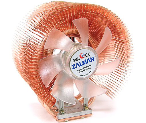
I know there have been similar designs in the past, like Zalman's flower tower, CNPS-9500, designs, but this design I have is drastically different.

Here is the basic premise behind the design that popped into my head.
EMH34Os.jpg


It is more or less what you expect from tower heatsinks these days, with heatpipes connecting from the base plate to the fins, but what I have tried differently is in how the fins are laid out.
I call it the 'XO' design.
If anyone still uses those older wire chrome plated fan grills, you might notice the resemblance in low impedance design.

Pros.
- Traditional axial fans used on tower heatsinks have dead spots at the corners and behind the hub. This design accounts for the deadspots by not having anything there.
- Axial fans have varying static pressure and air flow at different radius points of the fan. This design accounts for that by varying fin spacing.
- Unlike traditional towers, the heatpipes protrude at an angle, allowing overall height to be reduced
- The fins are already shaped in a shroud, so the airflow is forced to go over the fins and should have more optimal airflow throughout the fins
- Less materials used, which should lower the total weight of the HSF

Cons.
- This design is far more complex than traditional towers and would require more welding. I would expect 4 parts per fin and many layers
- The heatsink will likely only be optimal with the fan it was designed with and 3rd party fans could have poorer performance
- Less total fin surface area (square vs. circle, or something to that tune)
- No fan overhang to provide cooling around the socket

Unknowns.
- Is "less surface area, but optimal air flow" better or worse than "more surface area, but imperfect airflow"?
- Is it the center of the fan that has poor static pressure or is it the outer edges?
- Are the fin spacing difference at various intervals really that important?
- What sort of turbulence / noise differences are there from traditional towers?

I have read on hardocp that there was a program that could virtually model how well a heatsink design works, but that is beyond my technical capabilities.
Basically, what I want to know is, how well does this type of design work for heatsinks.
 
I hope you've filed a patent for this already before you decided to divulge all the details here...

In my own mind, this looks like a good design, but I am far from mechanically inclined. You should do more research on a fluid simulation program that could test your design. Or YOLO it and make one produced to test in the real world.
 
Designs I have seen that have been close to this did not cool as well as the normal tower cooler. You also add a far more complex assembly, tooling would also be much more expensive, as you need to make each fin it's own size, while most tower coolers have a single stamped fin. Over all that comes down to cost/performance. Thats assuming it was better, lots of programs can simulate thermal transfer for something like this,
 
Cost and complexity of manufacturing ruin this type of design. If you build any design around one fan, you're going to have a bad time. People like customization and there is no single fan design that covers everyone. Also while fin area in the corners don't do much, it is still better than nothing.
 
Here's my quick thoughts:

Too many bends in the heat pipes, and likely too long overall. Very likely the entire upper portion of the pipe (everything above the center of your circle) would probably be unnecessary.

Changing the density of the fins isn't really going to help. Typical computer fans have a dead spot behind the hub, and turbulent flow around the edges. The majority of the airflow is a ring that goes from the inside of the inner frame to just outside the hub. So if you're building for that, go for that flow pattern. Most tower coolers have plenty of fin space outside of that to take advantage of any other radiative heat transfer, and of course any other air flow in the case.

This looks far too complicated to manufacture. That's going to drive up costs, and I don't think you'll see performance any better than a typical "tower" design. If it costs even $20 more to make than a traditional design, but only provides 1C better temps, it's not going to sell.

To really analyze this, you're going to need a pretty complex thermal model. Something to consider before you spend those hours and hours: All the big manufacturers have done this analysis and come up with very similar designs. There's a reason they've all converged on something similar, and that's because it's the most optimal solution.
 
Last edited:
Bandalo Spot on.. Lot of unnecessary pronounced bends just doesn't add complexity to the overall design, but also mean unoptimal heat transfer, the center of that design will be likely very warm and the heatpipe wick will be most of the time just trapped there offering poor cooling performance, which is the main flaw of that design, the rounded fin pattern will prevent the airflow to reach the center of the cooler, you have to keep the fins cold which is where the heat is transferred not only the heatpipes, the focused shroud flow would not cool optimally the fins, so the heatpipes may present different thermal conductivity performance on different parts of the cooler.

Understanding the heatpipe basic function they rely on an easy and smooth as possible "phase transition" or "phase change" in more typical naming, the liquid need to absorb fast the heat from the source and transform it into vapor dissipating the heat through the pipe up to the "cold" interface which is nothing more than the head of the heatpipe then it transform into liquid again through capillary action with the help of the gravity and return to the heat source, which is where the main flaw with that pronounced bend will affect the thermal conductivity condensing all the heat in the center of the cooler, the capillary action won't be efficient as in that spot is going to flow against the gravity, not only in that part but also near the base of the cooler, that amount of bends certainly would make the heat to not be transferred optimally. this is why you never find any cooler with very pronounced bends or shapes, the design you are showing here show almost flat 45° bending not only once but twice without count the base, so it certainly should be improved there.

The design is good but not for heatpipe cooling, it would be more adequate for convection vapor chamber cooling which use lot of similarities with the heatpipes like the below example:

CFD_Vapor_Chamber_Heat_Sink_Design_v1.gif
 
Thanks for all the feedback.
That is a very interesting aspect of the heatpipes that I didn't know of.
What if theheatpipes were offset and crossed in the middle, rather than bent 90degrees?

For what it's worth, I think the best design would be the conventional tower heatsink, but using a blower fan.
However, I am also sure everyone knows how large and cumbersome a blower fan with 120mm - 150mm output would be
 
MrDeaf Interesting idea, but I think running the heatpipe in a circle would give better cooling .. like Zalman does in their CNPS9500, 9800 & 9900 coolers. The 9900 is only
94(L) x 131(W) x 152(H)mm yet cools as well as any of the top tier kings of the hill.
CNPS9900max_b_02.jpg


Araxie I like the vapor chamber idea, but I think fins on both sides would double it's ability to transfer heat into airflow.
 
I also think that the distribution of the heat pipes in the design needs work.

As it is, the heat pipes leave large spans of heatsink where you're relying on conduction instead of direct contact.
Simply running the heat pipes through your circles vertically would solve this with little effect on back pressure I think.

Notice in the post above how the heat pipes have lots of direct contact with the fins....


That said - I love the idea of using concentric circles and the block out for the dead spot behind the fan hub!
 
Thanks for all the feedback.
That is a very interesting aspect of the heatpipes that I didn't know of.
What if theheatpipes were offset and crossed in the middle, rather than bent 90degrees?

For what it's worth, I think the best design would be the conventional tower heatsink, but using a blower fan.
However, I am also sure everyone knows how large and cumbersome a blower fan with 120mm - 150mm output would be

Why do you think that fan will work best? Unless you have size restrictions, there is no reason to use them, they are ungodly loud for the air they move in relation to normal 120mm fans, this is why GPUs tend to sound like a rocket ship and be one of the loudest items in a build.
 
Thanks for all the feedback.
That is a very interesting aspect of the heatpipes that I didn't know of.
What if theheatpipes were offset and crossed in the middle, rather than bent 90degrees?

For what it's worth, I think the best design would be the conventional tower heatsink, but using a blower fan.
However, I am also sure everyone knows how large and cumbersome a blower fan with 120mm - 150mm output would be

I understand your interest, but you need to do some homework on the science behind heatpipes first. If you understand the physics, then the most efficient designs become fairly obvious. The problem then becomes tweaking the most efficient design into something that fits your application for volume, mass and price.

The same can be said for using a blower fan. More airflow is helpful, but only up to a point. Once you get past a certain flowrate, the heat transfer coefficient drops off rapidly. So even if you can put together a blower putting out 1000cfm, it's only going to give you a degree or two of temp improvement over a good pair of 120mm fans. And in the mean time it'll produce an ungodly amount of noise and vibration while driving up the cost significantly.
 
In a manufacturing sense, it is far easier to build plates that are exactly the same then it is to build multiple circle sheets of different sizes. Increasing quality control by multiples.
 
Also, because of the bend in the heatpipes, you cannot simply slide them into the fin array. You would need to cut a massive amount of material out to allow the pipes to fit that way, or else bend (and unbend) them as they are assembled.
 
Back
Top